Are you a beginner looking to learn how to 3D model with Autodesk Fusion? This step-by-step video tutorial shows you how to design and 3D model a cardboard box using Autodesk Fusion’s sheet metal tools. Give it a try!
Getting started
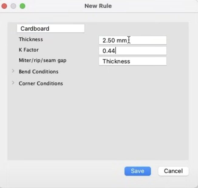
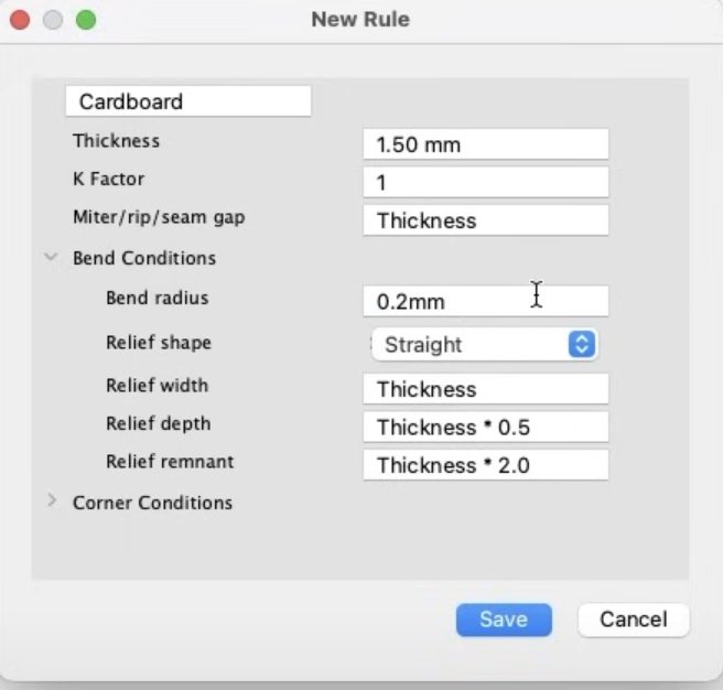
To get started, open Autodesk Fusion, create a new design, and navigate to the sheet metal tab within the Design Workspace. Our first step is to create a sheet metal rule specifically for cardboard. Since Fusion doesn’t have a default rule for cardboard, we’ll modify an existing rule, adjusting the thickness, K factor, and other parameters to match the desired cardboard specifications.
Next, we’ll set up parameters for the box dimensions, allowing for easy customization of the box’s width, height, and length to accommodate different requirements. Additionally, we’ll add a clearance value to ensure proper alignment with other parts.
Kicking off 3D modeling
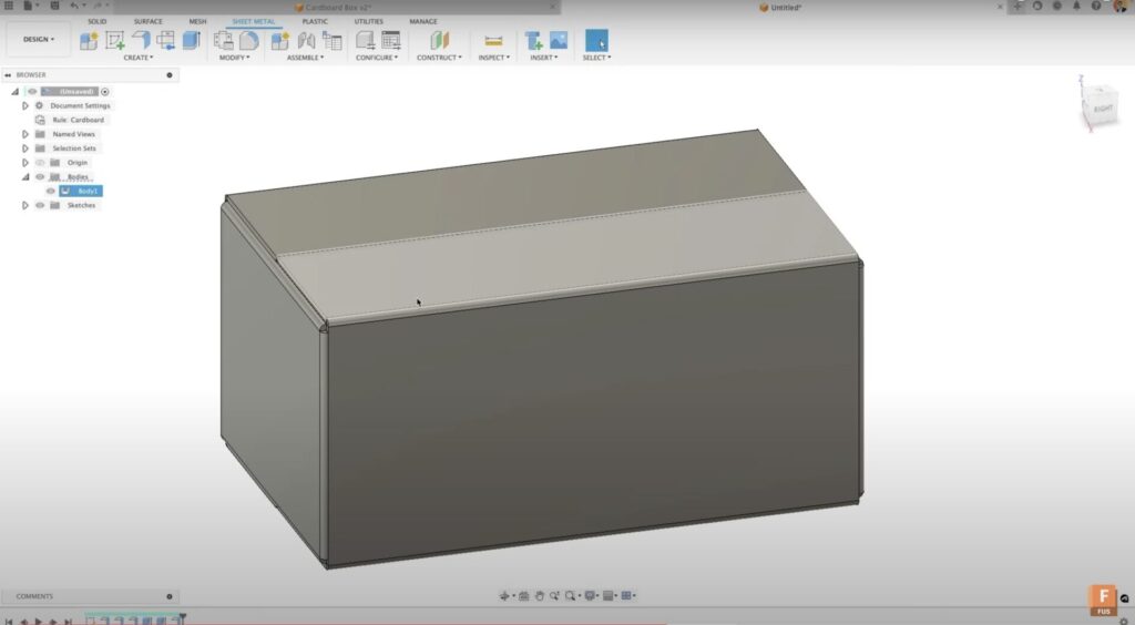
With the setup complete, we’ll now begin modeling the box. Using sketching tools, we’ll create a rectangle on the bottom surface, linking the dimensions to the parameters defined earlier. The flange tool will be used to pull up the sides of the box, following the sheet metal rules. Flanges will be added to close all four sides, resulting in a fully enclosed structure.
To strengthen the weak corner that wasn’t initially bent, we’ll add a tab on the inside. By utilizing sectional analysis, we’ll examine the inside structure of the box to determine the tab’s placement. The flange tool will be used again to create the tab, ensuring it is correctly positioned on the inside surface.
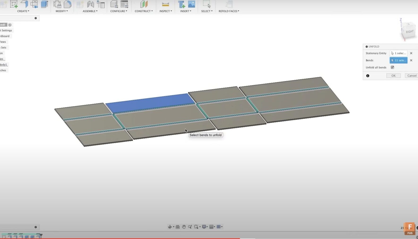
Once the box is fully modeled, we’ll demonstrate how to unfold it to check for errors or issues. Unfolding provides a visual representation of the flat pattern, which is useful for manufacturing purposes. We’ll also cover how to create a flat pattern and update it when design changes are made.
Exploring manufacturing options
Finally, we’ll explore the manufacturing options. The flat pattern can be manufactured directly within Fusion’s manufacturing workspace or exported as a DXF file for use with other manufacturing solutions. Fusion’s manufacturing workspace offers easy design updates and regeneration of toolpaths, making it a preferred choice.
We hope this comprehensive tutorial equips you with the necessary steps to start your 3D modeling journey with Autodesk Fusion’s sheet metal tools. Don’t forget to check out the Autodesk community for any questions or to share your creations on the Autodesk gallery. Stay tuned for more exciting tutorials from the Autodesk team soon. In the meantime, happy designing!