The real world is full of electrical noise. We are constantly moving in a sea of Wifi, radio-waves, cell signals, etc. Our designs need to be able to function reliably in the real world, so noise is an important design consideration. For some designs that are especially susceptible, differential signaling can be a useful technique to mitigate the influence of noise. By defining differential pairs, you can make sure that key signals in your design are protected from unwanted common-mode noise. This video tutorial walks through how to use Differential Pair Routing with Fusion 360’s PCB layout editor.
How does differential signaling work?
Two copies of the original signal are sent down a pair of paths with one inverted relative to the other. Now as the signals travel down the traces, they are both affected by common-mode noise (common-mode simply means that both signals are affected in the same way), so at the end of the trace, we have the following quantities:
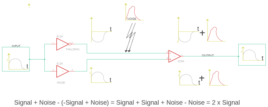
Trace 1 has Signal + Noise, whereas Trace 2 has -Signal + Noise. The op-amp at the end represents the difference operation (this is the origin of the word differential in the term “differential pair”) that is performed on the two signals to recover our original signal. So if we work out Trace 1 – Trace 2, we get:
Signal + Noise – (-Signal + Noise) = Signal + Signal + Noise – Noise = 2 x Signal
So, at the output of this configuration, we have recovered our signal and eliminated the noise that corrupted our signals as they traveled down that pair. This is obviously in ideal circumstances—in practical applications, the operation isn’t perfect, and the coupling between the two traces isn’t perfect either. However, this clearly illustrates the benefits of this type of architecture when working with signals in noisy environments.
Excercise
After showing how Differential Pair Routing works, the above video tutorial walks through how to apply that knowledge to a micro USB connector.
- After defining our connections, use the “Name” command to name your new signal. You will be using the same name with the difference of assigning the suffix _N and the next net _P. This will alert Fusion 360 of the existence of a differential pair configuration. At this point, the clearance between both traces can be defined using NET Class, but for this example, use the clearance setting defined in the “Design Rule Checker.”
- Next, use the Differential Pair Routing option available in the route pull-down menu. You will notice that all defined differential pairs will conveniently highlight. After selecting one of the signals, the other will simply follow alongside. Press enter at the destination, and quick route will end your routes. Traditionally, you would have had to finish each one independently.
- Set up your environment for Push and Shove with the “via” option enabled. This will make it so that as you route your Differential Pair, you will be able to move traces or “vias” that might be in your path. Once you reach your destination, press “enter” to have Quick Route finish this process for you.
- Finally, use the meander command to fine-tune your length matching. If meander are required, they will appear—on your mouse cursor you will notice the length difference by length and percentage.
Making your product smart is only one tab away. Accomplish easy Differential Pair Routing and explore more electronics capabilities with Fusion 360 today.
![]()