Learn all about how to measure and manipulate a circuit in your electronics design with voltage, current, resistance, and Ohm’s Law.
To grasp the true essence of electricity, one must understand how to manipulate and measure voltage, current, and resistance. We’ve climbed the highest peaks to find the right analogy to explain the nature of how electricity works in a circuit: our bodies in motion.
Elevate your design and manufacturing processes with Autodesk Fusion
What is Voltage?
Voltage is the electric potential difference between two points, representing the pressure that pushes electric charges through a circuit. It is measured in volts (V) and quantifies the work needed to move a unit charge from one point to another. Voltage powers electric current flow and is fundamental in electrical circuits.
Voltage – It’s All About Potential
Imagine waking up in the morning. You’re lying in bed, wanting just a few more hours of sleep, but it’s time for your dreaded morning run. You know it’s good for you, and you’ll feel great once you get moving, but every morning you have to make a choice. You can either stay in bed and sleep a little bit longer or get up and start moving your body.
This is the essence of voltage; it’s all about the difference in potential. We all have potential, and when it comes to running, the potential in question is making a choice of whether to run or sleep. If you don’t decide to run this morning, then your potential will sit dormant, but if you do, then that potential will explode outward, propelling you to run for miles and energizing the rest of your day.
Voltage in Electricity
Like having the potential to move or not, voltage is stored electrical energy with the potential for movement. It’s this voltage force that motivates electrons to flow in a circuit and keeps them running hour after hour.
Voltage is all around, just waiting for us to tap into its potential. Look at every unused wall outlet in your house. There is voltage buzzing in those sockets, ready to do work for you. But like making a choice to run, you have a choice of whether to tap into that source of voltage in your outlet. If left alone, then the voltage remains where it is, never realizing its full potential.
In an electrical circuit, voltage is measured by finding what’s called the potential difference between two points with a multimeter. Take a 9-volt battery, for example, if you measure the positive and negative ends, you’ll get a potential difference of 9 volts (or close to it). The positive end measures at 9V, and the negative end measures at 0V. Minus the two numbers, and you get your potential difference.
Types of Voltage
- DC (Direct Current) voltage: provides a steady stream of negative electricity.
- AC (Alternating Current) voltage: switches from negative to positive continuously.

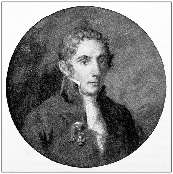
The Father of Voltage – Alessandro Volta

The man to first discover voltage was Italian Physicist Alessandro Volta. He also uncovered a ton of other cool things, including:
- Discovering that if you mix methane with air that you can create an electrical spark, which marked the beginning of the now-famous combustion engine.
- Discovering that electrical potential stored in a capacitor is proportional to its electrical charge.
- Volta was also credited with creating the first electric battery, called the Voltaic Pile, which allowed scientists of the time to create a steady flow of electrons.
What is current?
Electric current is the flow of electric charge, usually electrons, through a conductor like a wire. It measures how much charge passes a point in the circuit per second and is expressed in amperes (A). Current can be direct (one direction) or alternating (reverses direction). It is driven by voltage and is fundamental to powering electrical devices.
Current – Going with the Flow
Going back to our running analogy, imagine that you’ve made the choice to take that morning run. You have your shoes and running shorts on and walk out your door to hit the trail. At this point, you’ve got some movement going as you start your run, a flow.

Maybe an hour into your run and you start to hit your stride, ready to run for miles. As you run, your smartwatch measures exactly how far you went and how fast you traveled. This process of running and measuring the process is what current is all about.
Current in Electricity
Like taking steps to complete your morning run, the current is the constant movement, or flow, of electricity in a circuit. The electric current flowing through your circuit is always measured in Amperes or Amps. But what keeps this current moving?
It’s the voltage that we talked about earlier. Just like you need to tell yourself to keep running once you get tired, voltage is the motivating force behind current that keeps it moving. There are two schools of thought for how current flows in a circuit; Conventional Flow or Electron Flow. Let’s look at both.
Conventional Flow
Conventional Flow was first, in a period of scientific discovery when people didn’t understand electrons and how they flowed in a circuit. Under this model, it was assumed that electricity flows from positive to negative.
You’ll still see this mentality being used in schematics today, and though it isn’t entirely accurate, it is a bit easier to understand than Electron Flow. After all, if we go back to our running analogy, you start with a positive source of energy, and you run until you’re out of energy. It’s a positive-to-negative relationship, like many things in life.
Electron Flow
Electron Flow was the follow-up to Conventional Flow. This model accurately portrays electrons as flowing in the opposite direction, from negative to positive. Because electrons are negative by their very nature, they will always flow out of the negative and endlessly try to find their way to the positive, low voltage side of a power source.
Does it matter which way you display current flowing in a circuit? Not really. You’ll likely see it presented both ways when looking at a variety of schematics. Take a look at the diodes or transistors in the next schematic you examine; they’ll all be pointing in the direction of Conventional Flow.
The Man Behind Current – Andre-Marie Ampere

Ampere was a French Physicist and Mathematician. He was also one of the founders of the science of classical electromagnetism. You can thank Ampere for some pretty great stuff, including:
- His major discovery of demonstrating that a wire carrying an electric current can either attract or repel another wire that also has a current flowing through it without the use of physical magnets.
- He was also the first to bring out the idea of the existence of a particle that we all widely recognize as the electron.
- He also organized chemical elements by their properties in a periodic table a half-century before today’s modern periodic table came into existence.
What is resistance?
Electrical resistance is the measure of how much a material or component opposes the flow of electric current through it. It depends on factors like the material, length, cross-sectional area, and temperature. Higher resistance means less current flows. Resistance is measured in ohms (Ω) and follows Ohm’s law as R=VIR=IV, the ratio of voltage to current.
Resistance – It’s a Material World
Imagine your back out on the running trail. What kind of surface are you running on? If you’re lucky, then you might be cruising on a soft grass or dirt path. Or maybe you prefer the firmness of the street or sidewalk.
Regardless of what kind of path you’re running on, your feet are encountering some resistance as you continue to move forward. Naturally, not every path of resistance is created equal. Running through mud puts way more resistance on your ability to run when compared to running on a dirt path or street. This is what resistance is all about — the tug and pull of the material world.
Resistance in Electricity
Whatever kind of material that electricity moves through, it’s going to encounter some friction that resists its motion. To put it simply, resistance slows down a current. While there are specific components in an electric circuit like a resistor whose sole job is resisting electricity, any physical material will provide some resistance.
Resistance is measured in Ohms Ω, and it has a direct relationship to current and voltage. For example, the more resistance you have, the less current can flow through a circuit. It’s just like running, the thicker the mud, the slower you’re going to run. The opposite works as well, if you crank up the voltage to get your current moving faster then your resistance will have less of an effect on your circuit.
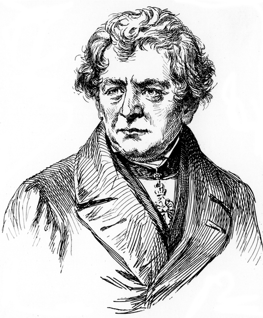
The Master of Resistance – Georg Simon Ohm

Mr. Ohm was a German Physicist and Mathematician, and it was during his days as a school teacher that he began his research using the new electric battery invented by Volta. With his own equipment, Ohm was discovered that there is a direct relationship between the voltage applied to a conductor (like a copper wire) and its resulting electric current. This came to be known as the now famous Ohm’s Law that we all rely on today.
It’s interesting to note that when Ohm presented his findings in his first book – The Galvanic Circuit Investigated Mathematically — the college that he worked for at the time didn’t care for it. So what did Ohm do? He resigned and got a new job at the Polytechnic School of Nurnberg. It was here that his work thankfully got the attention it deserved.
Putting it All Together with Ohm’s Law
Alright, it’s now time to put all of our concepts together. Here’s what we have to work with:
- Voltage (V) – Stored electricity that has the potential for movement. When this potential is activated, then voltage acts as a sort of pressure, pushing current along a circuit.
- Current (I) – The flow of electricity in a circuit. This can be measured directly in Amperes, and there are two schools of thought for how current flows – Conventional Flow and Electron Flow.
- Resistance (R) – The resistance that electricity encounters simply by flowing through some physical material. This is measured in Ohms.
What is Ohm’s law?
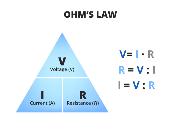
V=IR
Ohm’s law is a fundamental principle in electrical engineering describing the relationship between voltage (V), current (I), and resistance (R) in a circuit. It states that the voltage across a conductor equals the current flowing through it multiplied by its resistance, expressed as V=I×RV=I×R. This law helps calculate any one of these quantities if the other two are known. It was formulated by Georg Simon Ohm in 1827.
Using Ohm’s Triangle
Check out Ohm’s Triangle below. It provides an easy, visual representation of how you can manipulate Ohm’s Law to get the answers you need. To use it, all you need to do is cover up the letter of the value that you need to figure out, and the remaining letters show you how to get there.

Let’s say we have a 9V battery connected to a LED and a resistor. The only problem is that we need to figure out what is the value of the resistor.
To do this, let’s look at our Ohm’s Triangle. By covering up the R, we can see that we have V over I, or V divided by I. So by dividing these two numbers, we’ll get the value of our resistor. Let’s plug these numbers into this equation: R = V/I.
- Let’s start with the most obvious, our battery voltage is 9 volts.
- Looking at the datasheet for our LED, we can see a suggested max current of 16mA (milliamps), which converts to 0.016 amps.
- Plugging these two numbers into our equation gets us R = 9V/0.016A, which equals 473.68. This means we need a 473 Ohms resistor for our LED to turn on!
Resistance is Futile
Understanding how voltage, current, and resistance all work together wasn’t all that hard, now was it? The next time you go for a morning run, we hope you’ll have a new perspective on electricity. Feel your feet flying across the pavement or dirt, and remember that’s resistance. And when you check to see how far you ran, then you’re observing current in motion! And that force that got you out of bed and kept you running? Voltage.
Ready to make your first circuit today? Try Autodesk Fusion for free!