& Construction

Integrated BIM tools, including Revit, AutoCAD, and Civil 3D
& Manufacturing

Professional CAD/CAM tools built on Inventor and AutoCAD
8 min read
We are excited to announce the introduction of joint creation, non-associative edits, and local context to the Edit-in-Place (EIP) workflows.
Joint creation – New components created while in EIP can be properly jointed to prevent them from being repositioned in the assembly when exiting EIP.
If you are new to using joints or you commonly use the move, align, or capture position, we have created a quick primer on some crucial differences which can affect how the positions of components are calculated. Additional detailed information is specific to Edit-in-place below.
Default context becomes Local context – The initial release of EIP enabled the ability to create contexts from assemblies. When a context is created, the positions of components in the assembly are captured in the context, and activating the context positions all components as they would be in the assembly. The Default context was a representation of all components as they exist locally in the Xref without any influence from the assembly. Since the Default context represents the Local positions of the Xref components, we have renamed the Default context to Local context and have enabled the ability to activate the local context from within the assembly, making it even easier to toggle to a Local view of the Xref from within the assembly.
Non-associative EIP – Building components within the context of an assembly is helpful in many situations, but an associative context may not always be required or even desired. Non-associative EIP is a mode that prevents the creation of associative context.
The introduction of EIP changes how external references can be used in Fusion. EIP enables quick editing of externally referenced (Xref) designs, but it also allows associative connections between an assembly and an Xref. This means the position of a component in the assembly can associatively control features in the Xref. This connection to the assembly makes understanding positioning in Fusion 360 more critical than ever.
In preparation for concurrently working on a project with other designers, several new assemblies will be created and set up so each designer can work independently on their portion of the design without disturbing their coworkers.
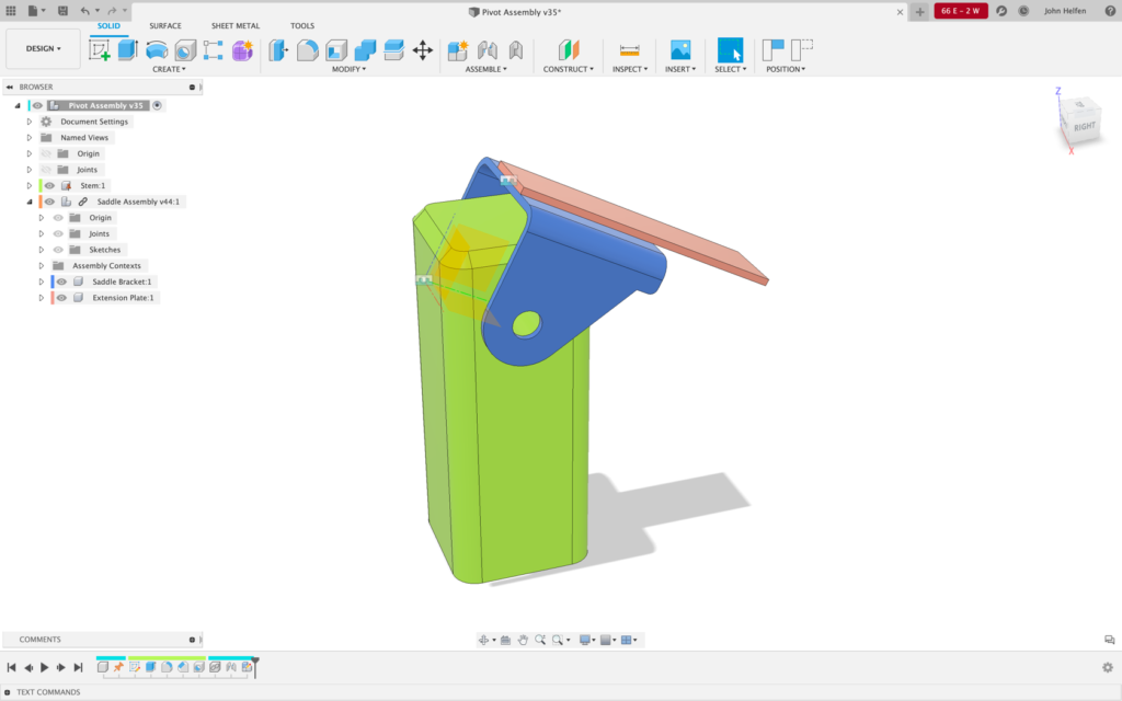
In the image below, a design has been created called Pivot Assembly, and it contains a local component called Stem (green). In the assembly below, there are 2 different origins, the main Pivot Assembly origin, and the Stem origin, which are sitting directly on top of one another. Most importantly, while they share the same location, they are not connected in any way.
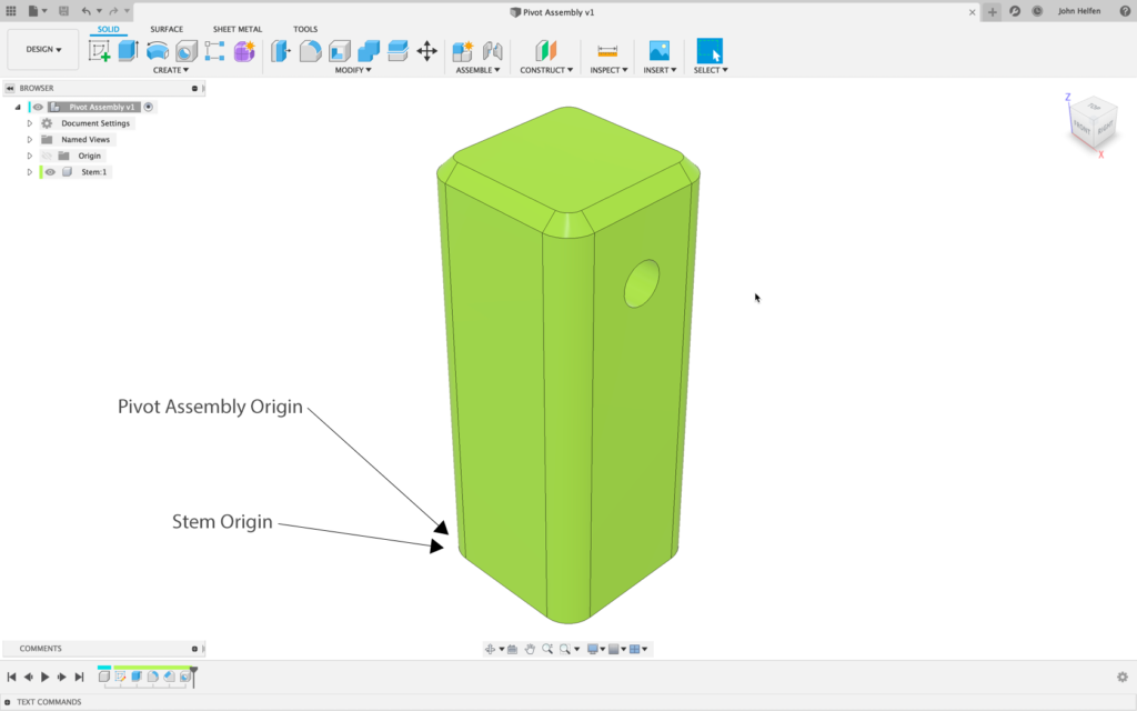
By default, the origins of a design are not visible. If both origins are made visible, and the Stem component is dragged away from its original position, it becomes clear there are two origins.
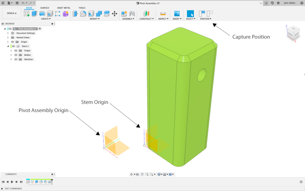
Once the Stem is dragged, the capture position options become available in the toolbar. If the new location is where the Stem component belongs, the capture option can be used to create a timeline marker and maintain the new location. However, if the position is Reset the Stem component is returned to its original position aligned with, but not connected to, the Pivot assembly origin.
A second design is created in the same manner; a Saddle Assembly is created, and it contains a Saddle Bracket component. Similar to the first design, this design also contains an origin for the Saddle Assembly and another for the Saddle Bracket. When positions are reset, these origins share the same location but are not connected.
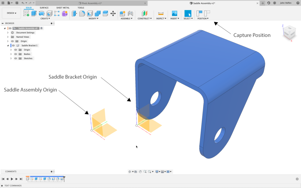
When the Saddle Assembly is inserted into the Pivot Assembly, it defaults to the origin of the Pivot assembly and a starting location and can be relocated as needed. There are now 4 origins sitting directly on top of one another.
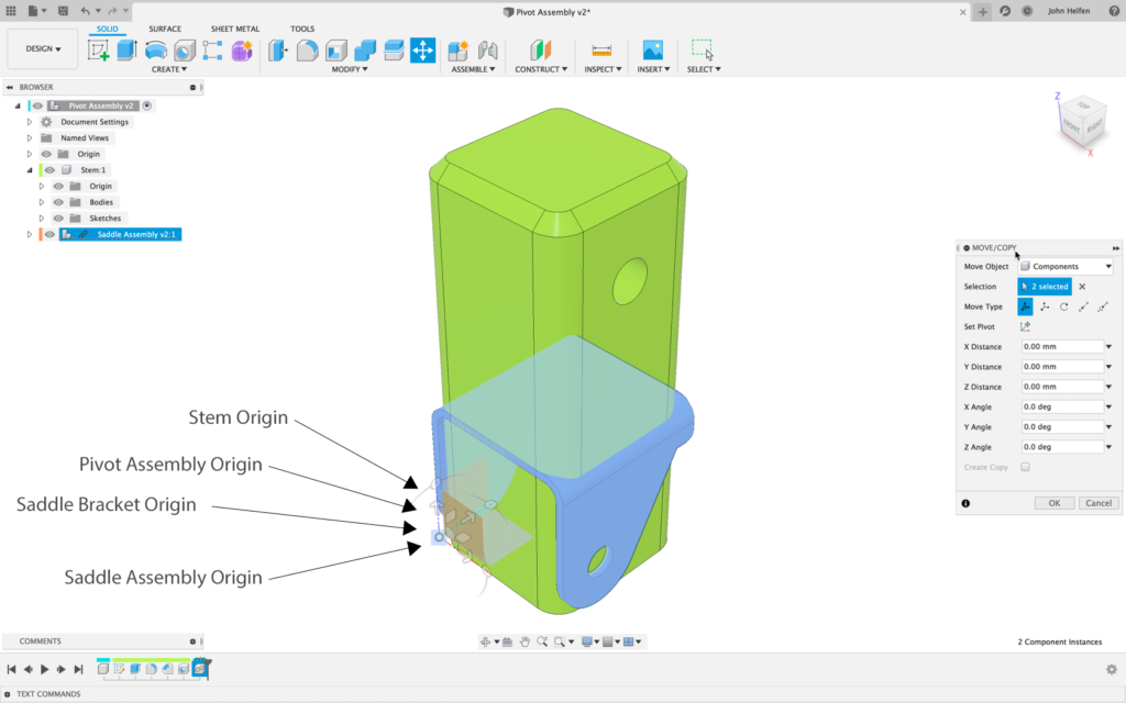
In this case, the Saddle Assembly origin will be positioned on the other side of the Stem for clarity on initial insertion.
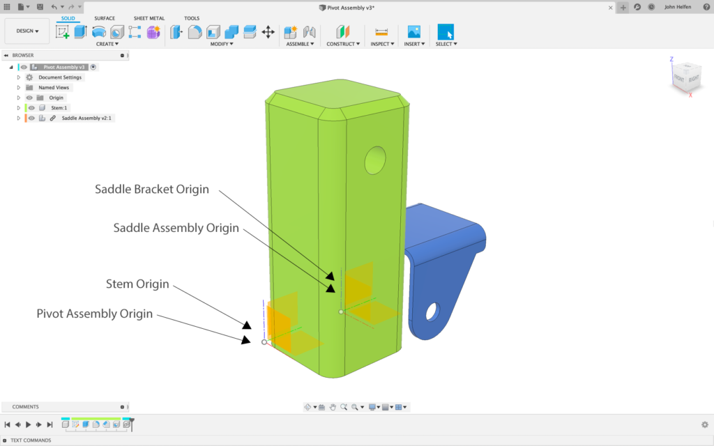
If the Stem and Bracket are dragged in the assembly, all four origins can clearly be seen.
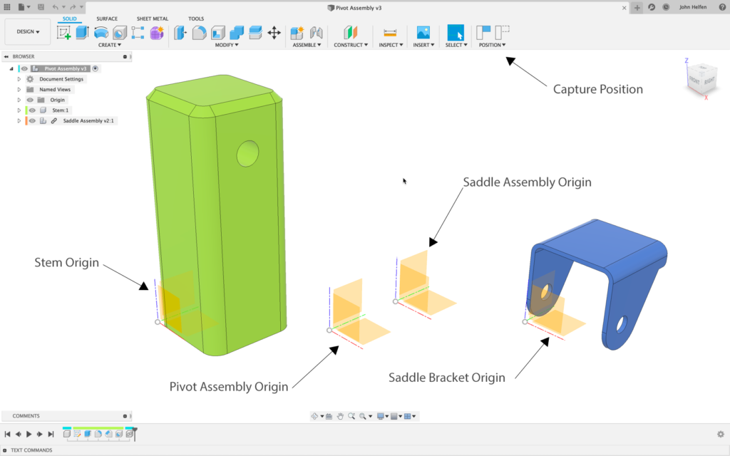
The bracket is connected to the Stem with a Revolute Joint. Because Fusion has fully flexible assemblies and the bracket is not connected to the parent origin, when the joint is applied between the bracket and the Stem, the Saddle Assembly origin is “”left behind””.
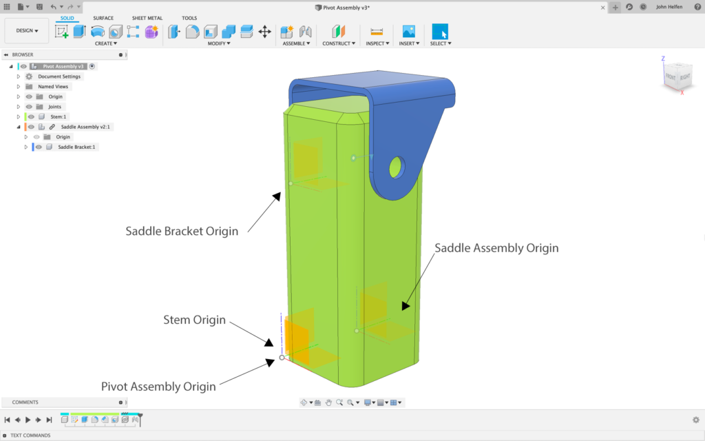
Before Edit in Place, this workflow was acceptable because editing of XREF’s’s happened outside of the assembly. Joints were added between components to ensure their connections to one another, and the location of the parent origin was somewhat irrelevant because it was rarely seen.
This “”disconnected-ness”” from the parent assembly origin may cause components created while in EIP to appear jump when exiting EIP or appear to be in the wrong location when in fact, they are correct relative to the “”unseen”” parent insertion point location.
Most designers are not aware the Saddle Assembly origin is being “”left behind”” when the bracket is joined in the assembly. With the introduction of EIP, the parent origin location becomes critically important.
Even after joints are enabled, and EIP moves from Preview to Public, components being disconnected from their parent origins can cause components to appear to jump when exiting EIP or appear to be the wrong location when activating an assembly context. At the same time, the XREF is opened on its own.
Below, EIP is started on the Saddle Assembly, and a new component, Extension Plate, is created. The extension plate is created in Place in the same way it would have been if the Saddle Assembly was open in its own tab. As soon as the sketch is created for the Extension Plate, a new Assembly Context is created to hold the position of components in the assembly. In this case, the Extension Plate is created offset from the Saddle Assembly origin.
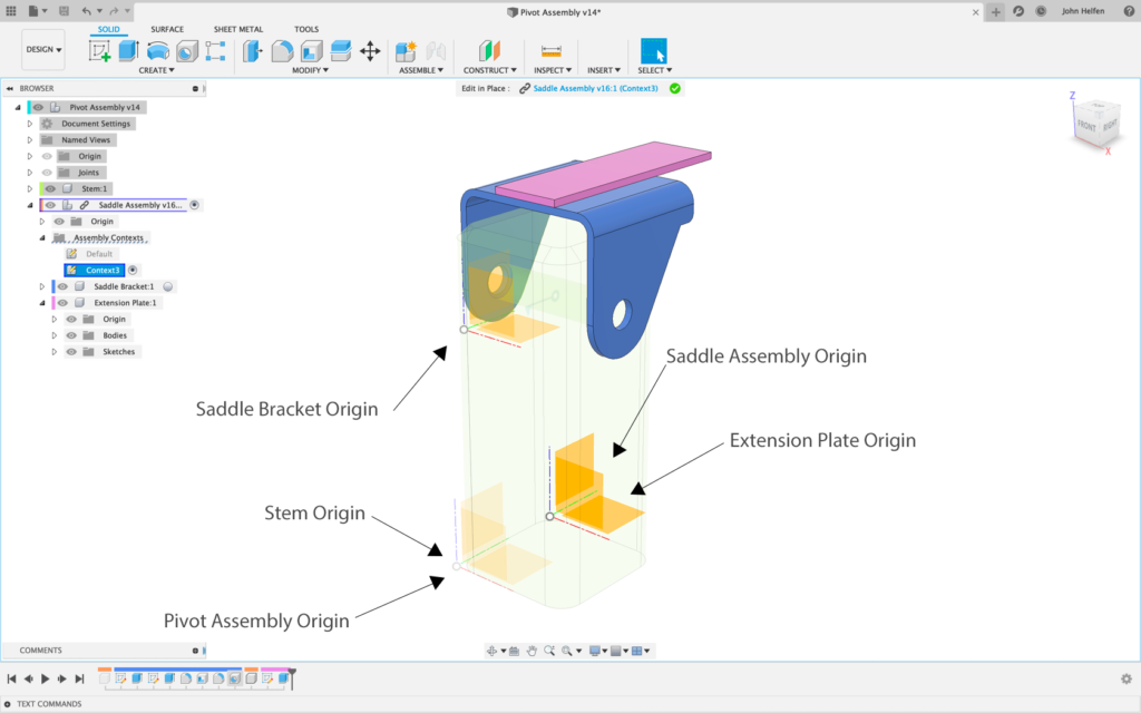
Upon exiting EIP and returning to the assembly, everything appears correct.
[icon name= ” “exclamation-circle” class=”” unprefixed_class=””] What is essential to understand is when the Extension Plate was created in EIP, and the assembly context was created, it was located on the bracket which had been moved away from the Saddle Assembly origin.
The joint that moved the Bracket lives in the Pivot Assembly.
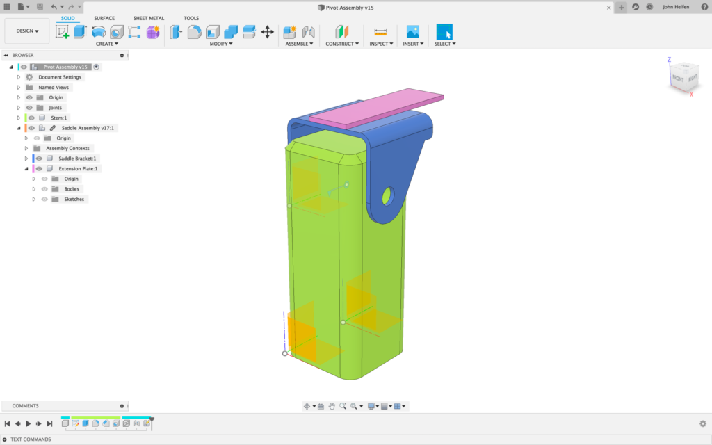
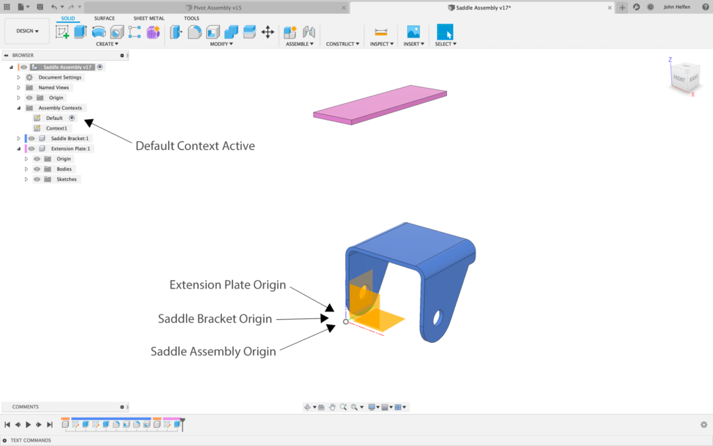
When the Saddle Assembly is opened in its own tab, the local context is active. The local context positions all components as they exist on their own within the design, without reference positions found in the assembly.
In the local context, the bracket is positioned on the Saddle Assembly origin because there is no joint to position it elsewhere in the XREF.
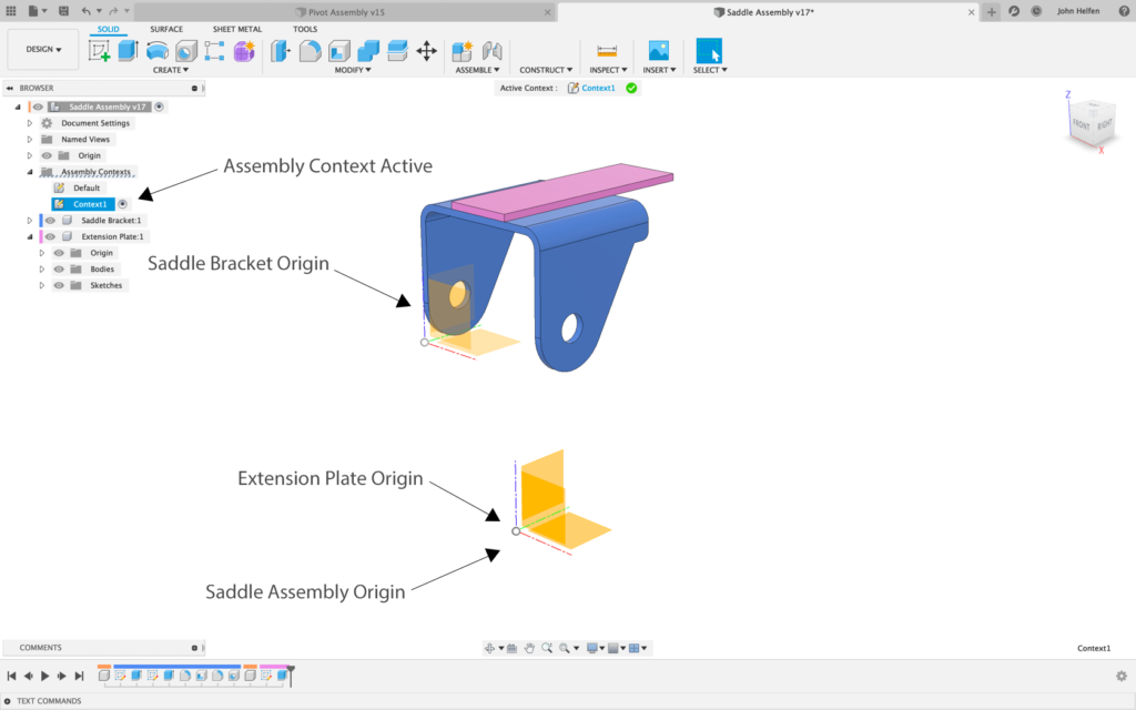
When the assembly context is activated, the component assembly positions captured during context creation will be imposed on the components in the design, and the components will be moved to where they were in the assembly. In this case, when the assembly Context is activated, the bracket is moved to the position it was in when the context was created.
What happens if components are connected to parent origin?
The design has been returned to a previous state, before the EIP session, creation of the assembly context, and the creation of the extension plate so that the bracket can be properly connected to its parent origin.

An as-built rigid joint must be created between the Saddle Bracket and the Saddle Assembly origin. The as-built joint will lock the two origins together and prevent the Saddle Assembly origin from being left behind when the bracket is jointed in the Pivot Assembly.

After resetting the position of the bracket, it is returned to its location at the origin of the Saddle Assembly. A rigid as-built joint is created between the two components by selecting each of the components in the browser.
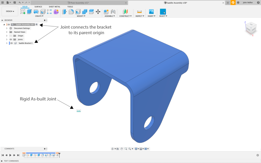
After adding the As-built rigid joint, return to the assembly and pull changes, and the Saddle Assembly origin is moved with the bracket in the assembly.
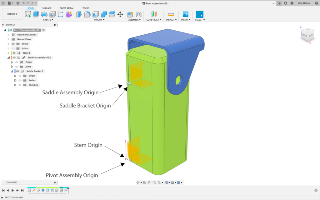
If we follow the same steps from earlier to create the Extension plate, all looks the same until we exit EIP.
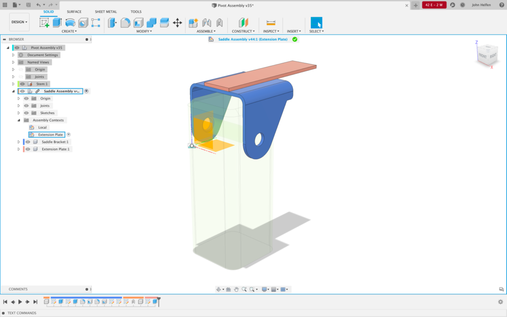
Because there is no joint between the bracket and the new extension plate when we exit EIP and return to the assembly, the extension plate position is calculated at the assembly level, and the extension plate is placed where it belongs relative to the Saddle Assembly insertion point.
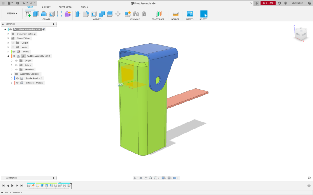
If we save the assembly and open the Saddle Assembly outside the Pivot assembly, all parts default to the proper location because of the connected nature of the origins.
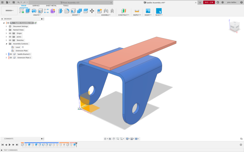
If we return to the assembly and edit the context, the extension plate will be placed where it was created, and a joint can be added between the bracket and the plate.

While active in the context, starting the joint command will automatically switch to the Local context and hide all the assembly level geometry. A joint, including as-built, rigid group, or standard joint, can be added to control the position of the part in the Xref.
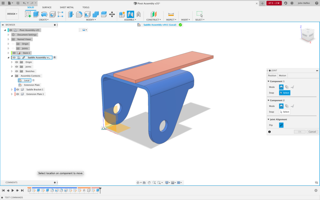
Once the joint is created in the Xref, and we return to the assembly, the component positions are calculated, and the extension plate is placed in its correct location. With the joint in Place components will move when motion is tested.
Edit in Place will remain in preview while we wrap up the feature, and we continue to look forward in hearing feedback on this new and exciting technology.
Please join the EIP Preview discussion on the feedback hub.
By clicking subscribe, I agree to receive the Fusion newsletter and acknowledge the Autodesk Privacy Statement.
Success!
May we collect and use your data?
Learn more about the Third Party Services we use and our Privacy Statement.May we collect and use your data to tailor your experience?
Explore the benefits of a customized experience by managing your privacy settings for this site or visit our Privacy Statement to learn more about your options.