For a PCB designer, using 3D Component Mapping in Fusion Library Editor to scrutinize and interact with your design in a 3D environment is more than a luxury; it’s a crucial part of your expertise. This ability to visually explore your design in a format closely resembling reality has become a vital design process step. It allows you to immerse yourself in the space where your creation will come to life, revealing nuances and potential issues that might be hidden in 2D representations.
Rotating, flipping, and delving into the board layers provides an intimate understanding of every trace and component, creating a connection that goes beyond the screen. Any change sparked by this interaction isn’t just about altering lines and pads. It’s about ensuring the design’s integrity and intent remain intact. Each adjustment in the 3D model resonates with the design’s intent and is mirrored in the 2D layout, preserving the coherence and precision of your work. This blog will guide you through importing 3D models into your libraries and mapping your footprints.
TIP: EAGLE Design and Library files are 100% compatible with Fusion Electronics.
Table of Contents
- Fusion library editor
- Access the data panel
- Accessing the Fusion library editor
- Import Footprint and 3D from other libraries
- Using IPC IPC-compliant calculator package workspace
- Linking components with 3D models
- Uploading and Aligning 3D Models
- Enhancing Fusion with Plugins
Fusion library editor
The Autodesk Fusion Library Editor is a transformative tool in our field. Its stellar integration with 3D modeling capabilities, especially for 3D Component Mapping in Fusion Library Editor, is especially beneficial for those dealing with complex assemblies, needing an additional layer of verification. The precision it offers in translating 2D data into a 3D model is noteworthy. This feature allows you to virtually inspect your design from every angle, identify potential assembly issues, and verify mechanical fit without a physical prototype.
The synchronization between the library and the 3D space is seamless. Any modifications you make are automatically updated, eradicating the frequent disconnect between electrical and mechanical design stages. It’s like having a real-time conversation with your design, where the feedback loop is almost instantaneous. For me, it’s about more than just the impressive 3D graphics. It’s about the confidence it instills in me about my design’s integrity before it even reaches the production floor.
Access the data panel
With Autodesk Fusion installed and launched, the initial workspace displayed is the Design Workspace. Before diving into the clicks within the Fusion component editor, let’s set up a foundation to help us stay as organized as possible. I have found that creating a project dedicated to your libraries is best. To accomplish this, click on the checkered box at the top right corner, which exposes the Data Panel.
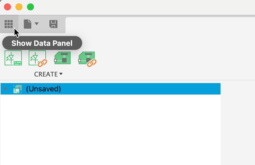
With the data panel expanded you can navigate your current projects or create new ones. We will create a new project called ‘Libraries’ for our exercise. Select the option ‘New Project‘ to make a Library project.
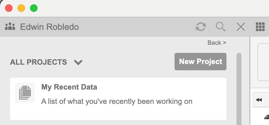
Once the project has been created, double-click to open it. Once you’re inside the project, we recommend setting up three new folders: one for uploading specification sheets, another for storing 3D model files such as Fusion or STEP files, and a third for the actual libraries. This organization makes it easier to locate files and streamlines the process for your team when searching for assets related to the library. Remember, you can assign and manage access levels for different team members to these folders. Restrict editing permissions for the libraries; although Fusion versions every change, an incorrectly built component can compromise the entire production run.
It should look something like this:
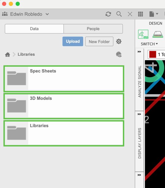
Our next objective is to master accessing and utilizing the Fusion Library editor for 3D modeling. This will enhance our ability to manage and use our digital assets efficiently.
Accessing the Fusion library editor
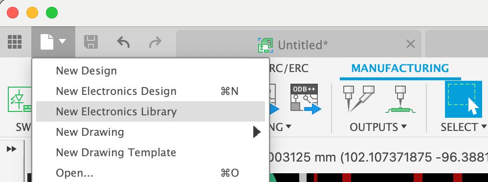
Within the Fusion Design or Electronic workspace, navigate to the ‘File’ drop-down menu and select the ‘Electronics Library Editor’ to initiate your session. It is imperative to consolidate all your libraries into a singular master ‘Libraries’ project. This method ensures a centralized source for your libraries, streamlining the design process. This guide will specifically focus on integrating 3D model assets into your existing libraries. For a comprehensive overview and in-depth guidance on library management within Fusion, refer to Jorge’s instructional video series on library utilization. With knowledge of how to access the library editor now established, let’s progress to the skillful handling of 3D models within your library.
Import Footprint and 3D from other libraries
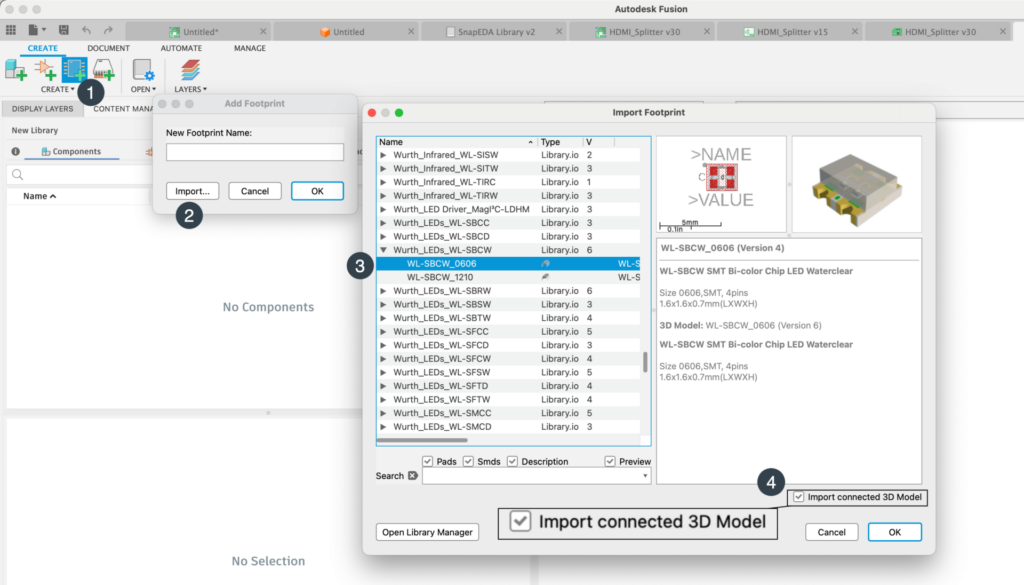
Welcome to the library editor in Fusion! To enhance your designs by importing Footprints with 3D models from other libraries, please follow this simple step-by-step process:
- Locate and click the ‘Import’ button in the library editor interface.
- Please browse the list of available libraries and select the Footprints you need, paired with their respective 3D models.
- Select the footprint you will need for your component.
- HINT: Make sure the ‘Import Connected 3D model’ option is selected
We’ve designed this procedure to be straightforward and efficient, ensuring you can seamlessly integrate diverse components into your projects.
This approach for importing a footprint and its corresponding 3D model from a library streamlines the component creation process. Footprint creation is often complex and time-consuming; reusing existing assets significantly reduces the time required. It allows for efficient recycling of components, simplifying and expediting the design process.
Using IPC IPC-compliant calculator package workspace
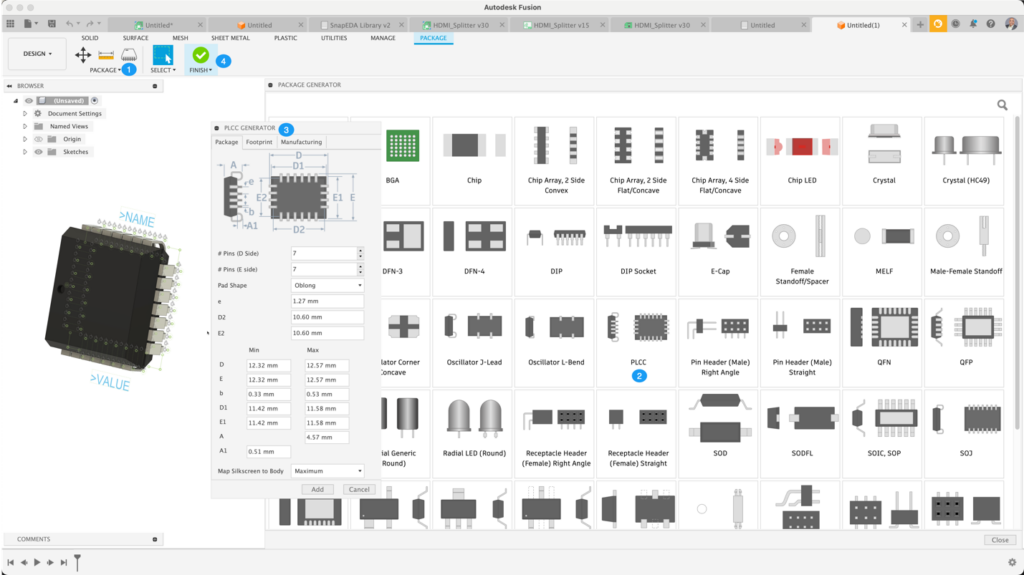
Getting started with the Package Editor in Fusion will make creating components for your design a breeze! The Fusion Library editor is fully equipped with all the necessary IPC Compliant component calculators. This means you can generate your component’s footprint and 3D model quickly. Imagine skipping all the manual measuring, grid setting, and pad placing—our tool does that heavy lifting for you. It’s not only a huge time-saver but also helps you avoid those little mistakes that can happen when you’re entering many details by hand.
Follow these simple steps:
- Open the Library editor and click on ‘New Package’.
- All the IPC-compliant generators are ready to use in the package editor area.
- Choose the template that matches your component, then pop the mechanical dimensions from your specification sheet into the calculator.
- Press’ Finish,’ and just like that, you’ve got a footprint complete with a 3D model that is accurate and will also give you realistic values for any thermal analysis on your PCB.
In conclusion, leveraging the Package Editor within Autodesk Fusion’s Library Editor enhances your design efficiency and empowers you with precision and accuracy. By utilizing the IPC Compliant component calculators, you can swiftly create footprints and 3D models, freeing you from the time-consuming intricacies of manual component design. This streamlined process accelerates your workflow and ensures that you have high-fidelity components ready for thermal analysis at your fingertips.
Linking components with 3D models
In the next workflow phase within Autodesk Fusion’s Library Editor, we focus on 3D Component Mapping in Fusion Library Editor, associating your electronic components’ footprint with 3D models. Whether you’ve crafted or imported one, you must have an existing footprint for this section. Generating footprints from a 3D model isn’t an option, but stay tuned for future developments. I’ve compiled a ‘Quick Tip’ video to assist you with mapping STEP files to your footprints. This video provides a visual and practical guide to mapping STEP files to your footprints.
Uploading and Aligning 3D Models
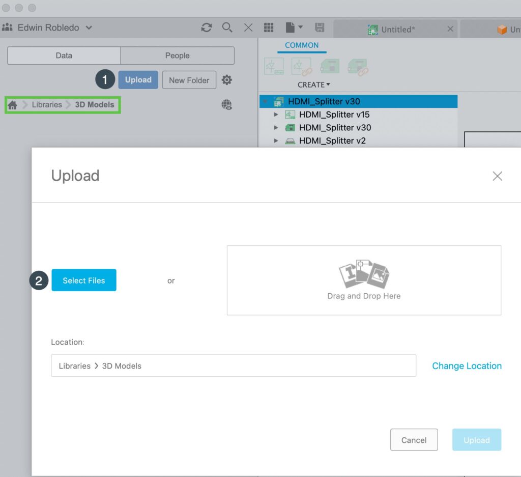
Before starting, ensure your 3D model is uploaded to the previously established ‘3D Model’ folder within the ‘Libraries’ project. This organizational step is crucial for managing models sourced from various locations and fosters an efficient workflow.
SnapMagic is highly recommended for its user-friendly interface. UltraLibrarian and Octopart are valuable resources for acquiring 3D models. Moreover, direct downloads from manufacturers or distributors, such as DigiKey and Findchips.com, are also viable options. After downloading your model, navigate to the ‘3D Models’ folder, click ‘upload,’ and add the 3D model file to your folder. We support STEP and Fusion Design file formats to accommodate your design needs.
The next step is significant for our mapping success. Navigate to the Fusion Library Editor footprint editor. From the list of footprints, right-click on the footprint asset in the selection list and choose the “Create 3D new Model” option from the context menu. This action will launch the package editor and display the Footprint in construction lines format, confirming that you are ready to map the 3D model.

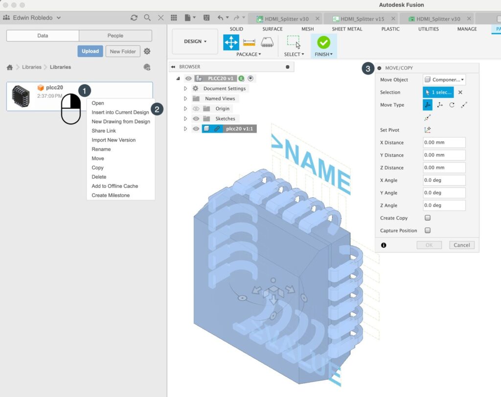
Once you’ve transitioned to the Package Editor, direct your attention to the Data Panel. Locate the previously uploaded 3D model. By right-clicking on the designated 3D model, the context menu will present an option to ‘Insert STEP file into the current design.’ Insert the STEP 3D model into the package, and align it using the provided adjustment tools with the footprint construction lines as your guide. Upon completion, select ‘Finish,’ at which point the system will suggest an IPC-compliant name for the package. You are at liberty to modify this to align with any internal naming protocols.
With these steps, you’ve successfully associated an existing Footprint with its corresponding 3D model, marking the completion of this phase.
Enhancing Fusion with Plugins
I would like to let you know of a few plugins we have available in Fusion to make it even easier to build electronic components in Fusion Electronics.
The Autodesk Fusion API dramatically enhances the software’s functionality, allowing developers to innovate custom scripts, add-ins, and automation that streamline the design process. It supports Python and C++ and provides access to a rich object model for creating plugins that can automate tasks and integrate with external systems. With extensive resources and a supportive community, the API facilitates a more efficient and personalized workflow, empowering developers to tailor Fusion to their needs.
Due to these API capabilities, 3rd party assets have been able to develop valuable plugins for Fusion electronics.
SnapEDA and Ultra Librarian have created plugins for Fusion. Please visit the Fusion Plugin store and look for these add-ons. We hope to add more valuable plugins in the near future.
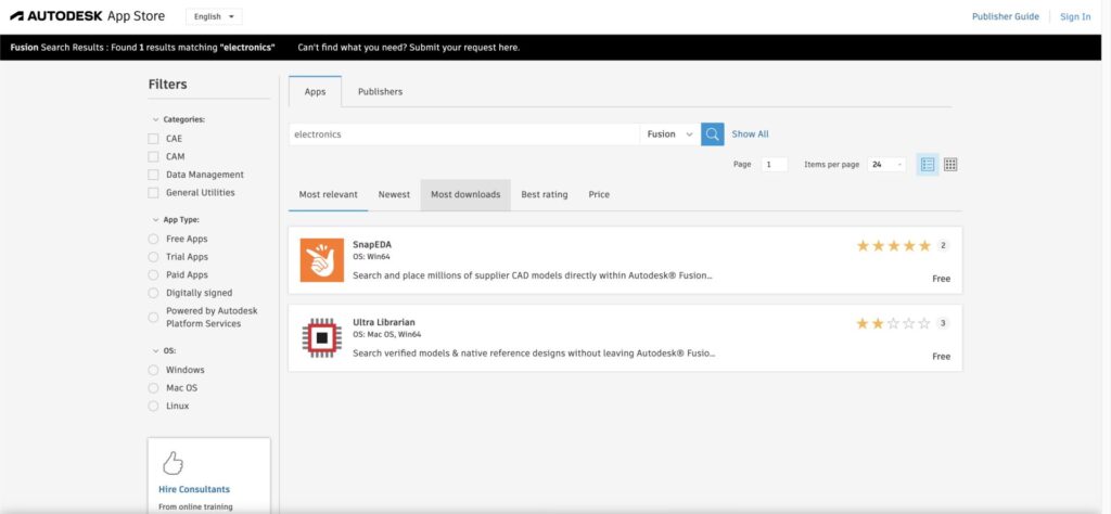
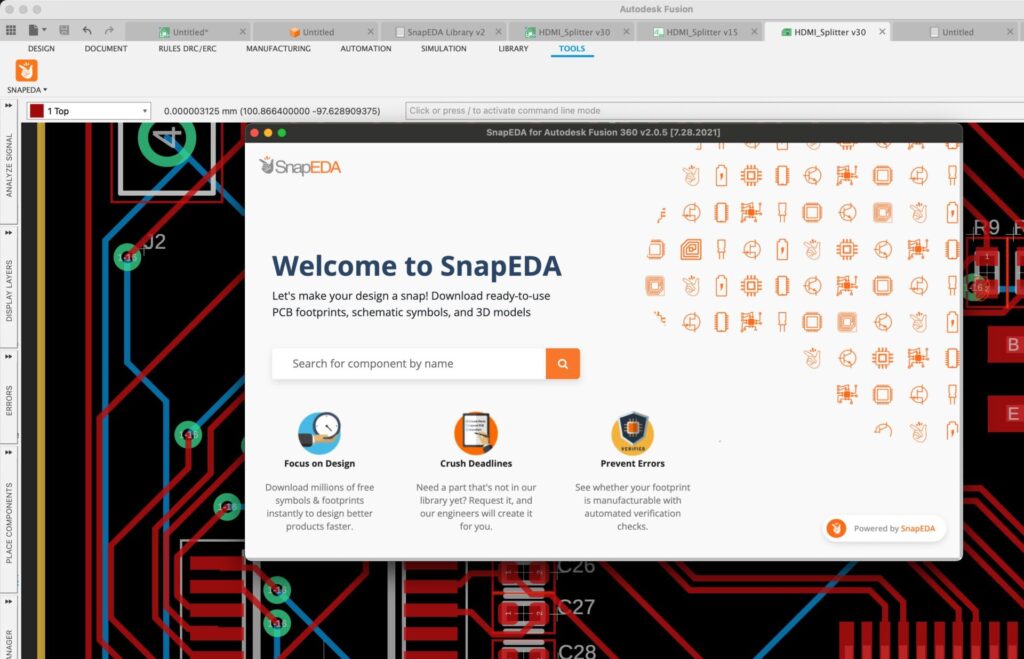
With the plugin installed, you can browse the vast repository of available electronic components. After selecting a download, you can create or use an existing library to build the requested part. If the 3D model is available, it will also be mapped. Watch this quick tip video, in which I provide step-by-step instructions for using the SnapEDA plugin.
In conclusion, the refinement of PCB designs within a 3D modeling environment, specifically through 3D Component Mapping in Fusion Library Editor, is more than a convenience. It’s now a key element of sustainable, collaborative electronics design. It’s not merely about aesthetics. This practical approach enhances accuracy, efficiency, and team communication, key elements for long-term success in PCB design.
The methods we’ve discussed enable accurate mapping of components to 3D models. This bridges the gap between digital blueprints and physical realities. By presenting various strategies, we’re establishing a new design and collaboration standard. This helps future-proof your workflows, keeping pace with advancing technology.