The extrude cut feature in Autodesk Fusion is essential for creating precise cuts in complex designs. This guide provides a professional overview of how to effectively utilize this feature in a valve design project, ensuring both functionality and precision.
Initiating the extrude function
Begin by pressing “S” on the keyboard to bring up the design shortcuts and select “Extrude.” This guide focuses on the application of the extrude cut feature in the context of a valve design.
Selecting the sketch
- Display and select:
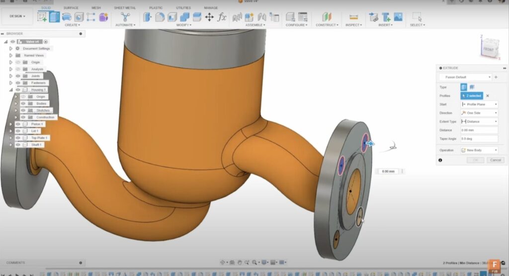
- Show the sketch and select the four holes that require cutting.
- As the cut is dragged through, the initial extruded cut becomes visible. Note that cutting through both plates simultaneously may unintentionally affect the main housing body.
Adjusting for multiple plates

- Profile selection:
- To avoid cutting through the main housing body, select the profile and choose two objects. This method confines the cut to the intended areas.
- This approach ensures that both plates are cut without compromising the main housing body.
Ensuring parametric updates
- Reactivate and select:
- If the part size is updated, the cut will adjust automatically.
- Reactivate the sketch and select the same profiles for another extrude operation.
- Set the “Start Condition” to “From Object” and select the plate from which to cut, using the drag arrow to adjust accordingly.
- Change the extent type to “Object” and select the opposite side, ensuring cuts on both sides of the plate.
Creating additional parts
- Utilize existing sketches:
- Use the same sketch to design other components of the valve.
- Select the face and set the start condition to “Offset Plane” with a 4mm offset and a distance of 10.
- This creates a new part based on the original sketch, aiding in the definition of the entire design.
Final extruded cut

- Execute the final cut:
- Use the shaft geometry to cut through the plate.
- Create a quick sketch on the top plane, project through the shaft, and establish a 1mm offset for clearance.
- Convert the line to construction geometry to simplify the sketch.
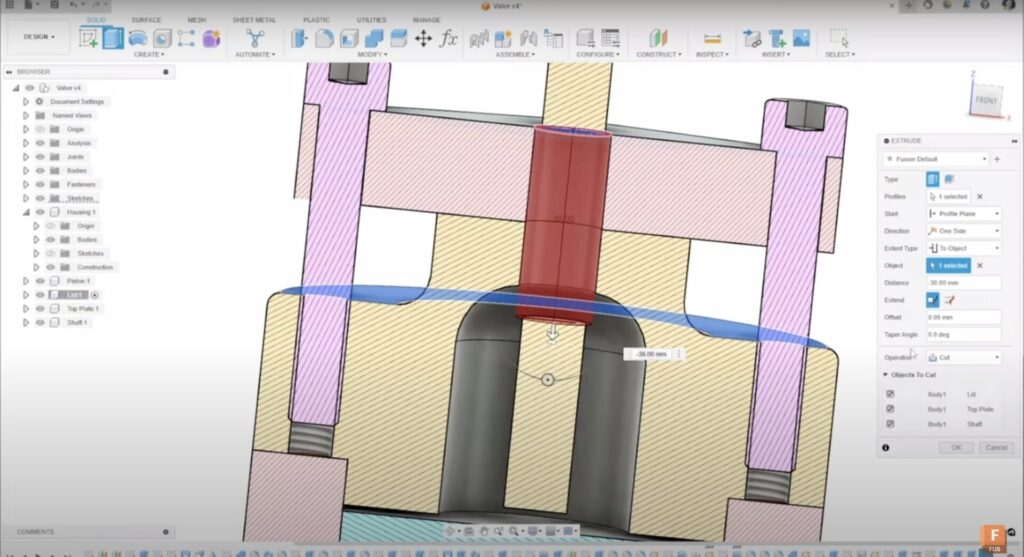
- Perform another extruded cut, dragging through to the top of the housing.
- Apply a section analysis to ensure the cut does not interfere with the shaft.
- Utilize the “Objects to Cut” tool to specify that the lid and shaft should not be cut, only the top plate.
The extrude cut feature in Autodesk Fusion is indispensable for detailed and precise modifications to complex designs. By following these steps, users can ensure that their designs are both accurate and functional. If this tutorial was helpful, please give it a thumbs up.