Are you a circuit designer looking for some tips to incorporate IoT in your PCB designs? Does the thought of implementing IoT seem challenging to you? If yes, then you are in the right place!
IoT has significantly gained popularity in recent years due to the increase in digitalization in all walks of life. All major electronics manufacturers are moving towards implementing IoT based designs, and some companies such as Google and Apple have captured the IoT market quickly.
What does it take to incorporate IoT into your product? What advantages does IoT offer when used in PCB related projects? Read on to find answers to all such IoT related questions.
What Is IoT?

Internet of Things (IoT) is the interconnection of electrical, mechanical, and electronic devices over a network where these devices can communicate with each other without the need for human supervision or interaction. Soon we will see that everything inside and outside our homes is online, be it devices, animals, plants, or even human beings.
What makes IoT so compelling that it gained so much popularity in such a small amount of time? The most significant advantage that IoT offers is that humans don’t have to bother monitoring basic things in the house. They can save a lot of time because the devices will track everything on their own.
What Are the Requirements for IoT Based PCB Designs?
As a designer, to introduce IoT in your PCB designs, keep a few things in mind. Introducing IoT means that your PCB design must suit your targeted audience; hence, there are specific requirements that designers need to keep in mind when working on IoT related projects. Check out these top seven areas to consider:
1 – Compact Size
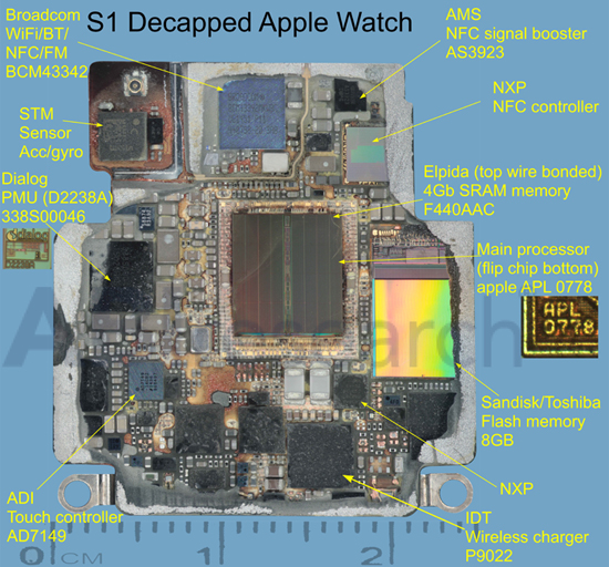
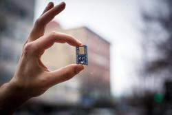
When designing an IoT device, you won’t have a lot of space on your circuit board. You would need to put the components as close to each other as possible so that your PCB is not too large. IoT devices are usually very compact; hence designers need to produce small designs. Using proper high density (HDI) design techniques will be a must to ensure the proper PCB integrity.

2- Long Battery Life
Since IoT devices need to be connected to a network at all times and communicate with other devices, they consume a lot of power. As a designer, you must ensure that your design is optimized to make the best use of limited battery capacity. Low power modes and minimizing parasitic consumption are critical.
Some commonly used batteries that can store charge for a long time are; Button Type Lithium Cells, Lithium Thionyl Chloride Batteries, and Lithium-Ion Batteries. For remote controls and thermostats, you can use AA Alkaline Batteries, Nickel-Cadmium Batteries, and Coin Type Lithium Cells.
3- Minimal Components and Light Weight
PCB designs for IoT projects must have a minimum number of embedded components so that they do not weigh too much. For instance, consider designing an IoT based wristwatch. No one wants to carry a considerable amount of weight on their wrists. So, as a PCB designer, you must make sure that the wristwatch weighs as little as possible so that the person who wears it feels comfortable.

4- Noise Reduction
PCB designs for IoT purposes must be designed such that there is minimal noise. Since the devices mainly need to communicate with each other, noise can hinder the communication process and introduce errors.
Electronic noise and reflection noise are two of the most commonly present in PCBs. When the frequency of signals increases to MHZ and GHz, an electromagnetic wave is generated from components that are picked up by other components as electronic noise. This can be eliminated by using noise filters and grounding/powering as much board area as possible. On the other hand, reflection noise is generated when the signal travels from one component to another. A change of medium occurs, which causes the reflection of part of the signal. This reflected signal bounces off other components until it is absorbed by one of them. Reflection noise can be reduced by using damping resistors, maintaining a consistent trace width, and reducing reflection points by back-drilling vias.
5- Antennas for Communication
Reliable antennas designed for the right frequency are essential for developing an IoT based project. As a PCB designer, you must know how antennas are placed in the right direction and what length is required for the devices to communicate via RF (Radio Frequency) technology. Antenna performance is significant when it comes to IoT based designs.

6- New IC Packaging
IoT devices these days are not using the same old surface mount and through-hole IC designs. They use more sophisticated and specialized packaging such as 3D ICs, Multi-Chip Modules (MCM), and System-in Packages (SiP). These newer technologies allow designers to produce compact circuit boards that are suitable for the IoT industry.

7- New Flexible Materials
Have you ever heard of flexible PCBs? IoT projects sometimes require flexible PCBs, which can be easily folded or bent according to the application. As a PCB designer, you must always be ready to shift towards flexible PCB options and materials, if you are planning to incorporate IoT in your designs. These new materials require special attention and design techniques, be sure to reach out to your manufacturer for guidance.
How to Incorporate IoT in Circuit Design Projects?
Now that you know the basic requirements of incorporating IoT in PCB designs let’s look at how you can introduce IoT in your PCB designs.
Recording and Sending Data

The first step that an IoT device does is take an input, record it, and then send it to the recipient. How does it take input? Well, the answer is simple. Sensors are used to take an input, for instance, if you are working on a device that measures distance and takes it as an input to perform further tasks, you might need to include an ultrasonic sensor in your circuit design. Similarly, another device could take temperature as input, and for that, you would need to use a temperature measuring IC in your project.
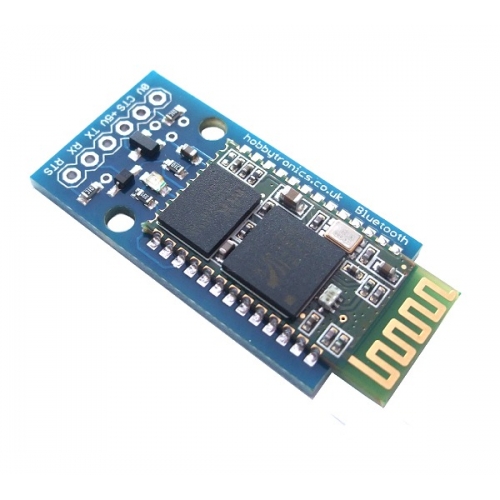
After taking the input, the device decides whether it needs to send this information to some other equipment such as your mobile phone. If it does, you need to add a data transmitter chip such as a Wi-Fi or a Bluetooth chip. You may even consider adding a GSM module, which can allow you to send information through SMS on your mobile phone.
Receiving and Processing Data

The second phase is that a device receives data and acts on it accordingly; for that, you would need to use one of the communication methods as mentioned above. For processing purposes, you would need to include a microprocessor chip in your PCB design, which processes the data it receives.
For instance, if you are designing a home automation system that controls lights. The lights only switch on when a person enters a room and turns off when the person leaves. This requires the LED’s to receive a signal as soon as someone comes through the door, by placing a sensor circuitry on the door which wirelessly communicates with the LED’s and tells them to turn on. These signals are processed through a microprocessor chip; hence, adding microprocessors to your PCB designs can incorporate IoT. A powerful microprocessor chip that can be used in IoT applications is the Ingenic M200 microprocessor. Atmel processors are also a good choice for IoT designs, some of which are ATMEGA328P-AU, ATMEGA328P-PU, and ATMEGA2560-16AU.
Power Management
An essential part of IoT is how the power management system would work and what would be the source of power for the IoT device. As mentioned earlier, battery life is essential for IoT devices because they are always connected to the network and are communicating with each other majority of the instances.
For better power management, the device should be equipped with a battery that can quickly store a substantial charge. Wireless charging and energy harvesting is another concept that is surfacing in the field of electronics, and this could also be implemented in IoT devices so that they can be charged through Wi-Fi signals as they continue to communicate with other devices.
As a designer, you should opt for better power management options to incorporate IoT into your designs.
An Example: Implementing IoT Based Temperature Controller

IoT is often used for home automation, and one such example is a room temperature regulator. This device monitors the temperature of the room it is placed in and sends the data to a PC or mobile phone over Wi-Fi. When the temperature rises above a specific temperature, for instance, 30oC, then the temperature monitoring device prompts the air-conditioner or the fan to start cooling the room.
When the room cools down to a specific temperature, say 25⁰C, then the device prompts the AC or the fan to turn off. In this way, the temperature of the room stays within a range of 25⁰C to 30⁰C. In this example, we are using Arduino Nano as a microcontroller, ESP8266 Wi-Fi module, and LM50 temperature sensor IC. Review the basic model schematic diagram shown above.
This is a simple approach to implementing IoT in home automation. As a designer, you can design more complex circuits to incorporate IoT in your project. Instead of using a microcontroller board, you can use a microcontroller chip along with a Wi-Fi chip. Making the project compact and easy to assemble on a PCB.
Ready for Implementing IoT In Your Next PCB Design?
By now, you should understand that designing PCB boards for IoT applications is different from typical PCB design. It would be best if you were more vigilant while working for an IoT based PCB design.
If you keep all the factors mentioned earlier in mind while implementing your future IoT related PCB design, then we are sure you will achieve a very sophisticated PCB design.
Download Fusion 360 and start designing your next IoT PCB Today.