& Construction

Integrated BIM tools, including Revit, AutoCAD, and Civil 3D
& Manufacturing

Professional CAD/CAM tools built on Inventor and AutoCAD
12 min read
Learn what the Fusion 360 team has worked on in the design and engineering spaces as part of Fusion 360 Development Update Week.
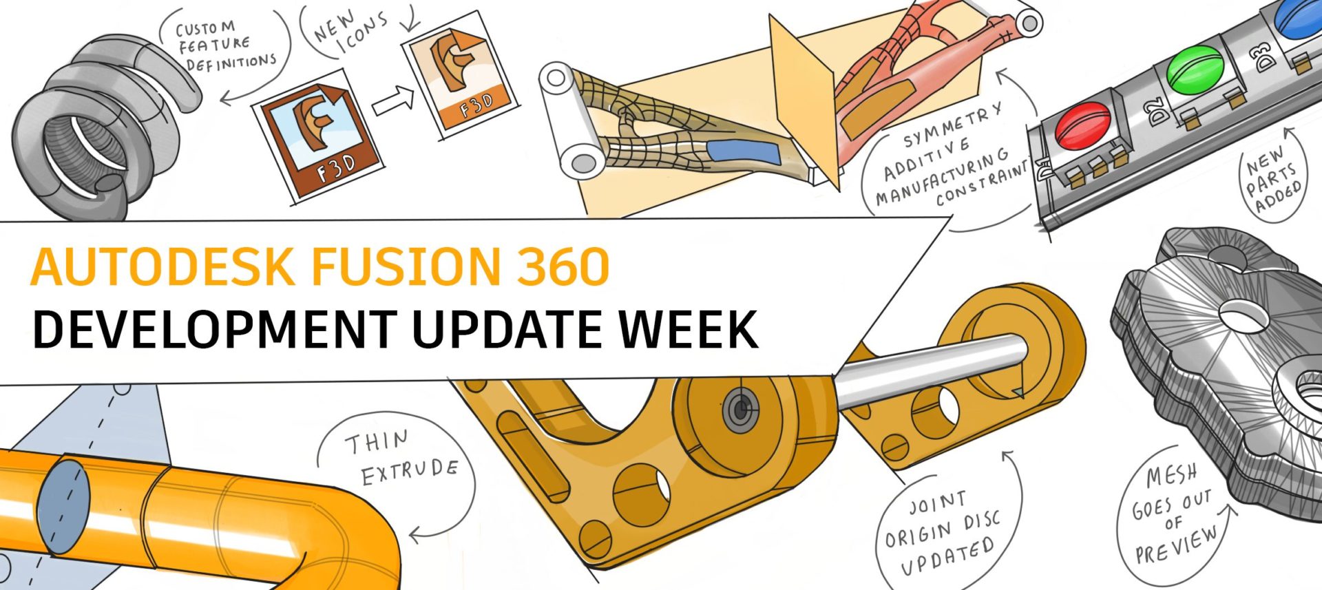
Our quarterly Development Updates give you an inside look at what we’re currently working on and offer a sneak peek at upcoming projects in our pipeline. During each Dev Update Week, we’ll publish separate articles dedicated to Design & Engineering, Manufacture, Usability, Collaboration & Data Management to give you a thorough picture of how we plan to develop each sector. These updates come straight from the source—our product team—the Fusion 360 team members working hard daily to bring you new features and improve existing workflows. Without further ado, let’s dig into the latest Design & Engineering update.
When we first introduced Fusion 360, we very intentionally set out to disrupt the CAD market with a new, modern approach to design. We wanted to put professional tools in the hands of anyone that wanted to make anything. Heck, that became our new slogan – Make Anything. Seven years into that journey, it’s fair to say we’ve made our way into the hobbyist and maker market, empowering people that have never used a CAD tool to make their dreams a reality.
That primary target audience for design (CAM had a different target user): those brand new to CAD formed the basis for many of the decisions we made around where to invest, what experience to create, and the baseline for the depth of capabilities that user has needed to be successful. The result of that effort ended up in almost always the same story – if you were new to CAD, Fusion 360 spoke to you, and it likely took you less time to learn it than other CAD tools. On the other hand, if you had any experience with tools like Inventor or SolidWorks, you had to un-learn (yes, that can be a word) what you knew about modeling, which led to more than a few experienced users being frustrated with the experience.
Over the last couple of years, we’ve been intentional when shifting our focus from individual users who are new to CAD to experienced, multi-disciplined teams of professionals who work on the same design at the same time. Our advancements certainly don’t abandon the needs of makers and hobbyists, as many are now creating more advanced products. Their requirements of Fusion 360 are growing in line with our users that have years of experience using tools like Autodesk Inventor.
That’s a long way around describing the most significant changes we’ve made to how you can use Fusion 360. We believe everyone should take the time to understand better what modeling methodology they should adopt. Before this year, one Fusion 360 design document could be a single part or assembly where you designated the difference between the parts by designating which bodies are components. This flexibility allows for fast conceptual modeling. Users didn’t have to worry about the CAD structure to get their designs on the table. And for individual users that design the bulk of a product without others actively contributing to the design, this will continue to be a great workflow. People usually describe this workflow as Top-Down or Multi-Body modeling.
Over the last year or so, we intentionally created an experience for you through what we call Bottom-Up or Distributed Modeling, where each document can be its own part. You insert those parts or sub-assemblies into documents designated to be the assembly as references.
This process is different for anyone with experience with other CAD applications; it’s clear what a part is versus an assembly is. In other applications, it’s an entirely different file type. The software presents various tools in an “Assembly” environment vs. a “Part” environment, often creating confusion. Bottom-Up or Distributed Design Modeling is excellent when using the same part in multiple assemblies. It’s also a great way to distribute work between multiple project contributors.
The result was five key projects that we delivered this year:

Edit in Place allows you to access and make changes to an externally referenced file (Xref) from within the context of a parent design. We don’t intend for Edit in Place to altogether remove the need to open an Xref in its own window while designing. Instead, it reduces the need to jump between design tabs to edit features in each Xref.

Edit in Place also enables associative connections between an assembly and an Xref through Assembly Contexts. Assembly contexts allow you to access part of the assembly from the external design without having to open the main assembly. You can pull updates at the assembly level into the distributed design by synchronizing the assembly context. When the assembly context is synchronized, features referencing the context will update accordingly.
Assembly contexts give designers access to critical assembly components without having to work in the larger assemblies. Instead, designs can work in their specific areas of focus independently while maintaining the connection to the assembly.
Experienced design teams often distribute Assembly Modeling work among multiple designers. The distribution of labor divides tasks based on areas of a product or team specialties.
Changes often happen in the early phases of development, and multiple collaborators may need access to a design. Many designers working closely together in a distributed design can lead to conflict. It isn’t easy to see who is accessing a design at any given time. As teams collaborate, this visibility is critical for an efficient design process.
Teams frequently struggle with is the dreaded “stomp.” If you’ve worked on a team before, you may have experienced the moment you realize your changes overwrote or “stomped” your teammate’s changes. This conflict is never intentional, but it does interrupt the design process and wastes time.
To help reduce these conflicts, we introduced Design Reservation and Avatars.

These changes make it easier for small teams to work concurrently on an assembly giving designers visibility into who they are working with, details on what those collaborators are doing, and additional flexibility from Fusion itself.
We have enhanced avatars to be more visual and responsive. They now appear in the data panel, browser, and active document tab when multiple people access a design at once.
Projects requiring multiple designers typically begin with a discussion about who will be responsible for different areas of a design. When you open a design, it immediately becomes apparent when other collaborators have parts of this design open, and everyone knows who is in the vicinity before making changes.
The active document tab expands, showing each collaborator and the name of the design they have opened. Hovering over each displays the full name of your collaborator and highlights the item they have opened in the graphics window.
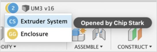
A Reservation Badge is a white dot applied to the lower-right corner of a project member’s Avatar while editing a design. The Reservation Badge indicates that the project member has made a savable change to the design. That project member reserves the design until they save or discard their changes.
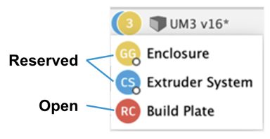
Avatars and reservation badges provide designers with instant access to valuable information. In the image above, collaborator RC has the build plate open but has not changed anything. Collaborators GG and CS include the Reservation Badge indicating reserved status. This badge tells others that active editing is happening and that they can expect changes in those designs.
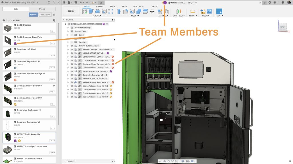
Learn more about Design Reservation and Avatars here.

Over the past six months, we’ve started shoring up our modeling foundation. We’ve been laser-focused on ensuring that customers can achieve the final results they have been looking for in the most reliable way possible. We’ll continue down this path and make sure we build a differentiating design environment for our customers. We’ll provide more flexibility, world-class toolsets, and dynamic modeling techniques to give you a solution that can scale and grow as you scale and grow your company.
We are doubling down on joints. Over then next year, we will significantly advance the joints toolset, unblocking previously blocked workflows.
Below are a few of the areas we have invested some significant effort in:
We know this is a staple of any toolset and is one of the most commonly used tools within the Design environment. We spent some time making the extrude foundation stronger and adding additional options such as Thin Extrude along the way. These updates are the foundation for future tools, so watch this space.

Right now is a super exciting time for Assemblies, and Joints is no exception. We’ve been making it easier to understand the position vs. motion of a relationship between components and the orientation of Joints when Joining components. We’re doubling down on joints, and over the next year, you’ll see the joints toolset be significantly advanced, unblocking previously blocked workflows.
We purposely prioritized significant work around patterns. We understand that patterns can be tough to use sometimes and that what’s happening can be tricky to track. We decided to go back and look at the code and make sure it was working the way it should, and we found it wasn’t. Since then, we have made significant strides to make patterns faster, predictable, and easier to manage. We’ll be adding more functionality over the next few years to make pattern creation even better.
One of the areas of the products that we have spent time slowly making better is the surfacing toolset. We added and improved Ruled Surface and Untrim. We made tons of progress in fixing and building a robust and comprehensive loft tool. These updates are not the end — our goals are lofty. We’ll be adding additional, world-class surfacing toolsets to enable you to build the exact model you need and give a greater level of flexibility and robustness.

It’s been a busy year for the drawings team so far. Here’s a snapshot of some of the work we’ve done.
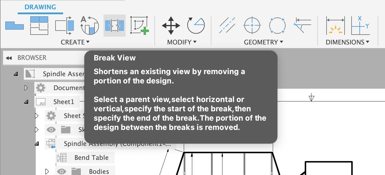
Initially available as a tech preview, this feature allows users to “break” views of longer parts for easier detailing. This feature evolved with updates in April and May. The upcoming September release will support breaks in non-base views and will support crossing or hybrid breaks.
You asked, and we delivered. Hot off the heels of Welding Symbols, we added Taper and Slope symbols, as, with all of our symbols, they conform to ASME and ISO standards.

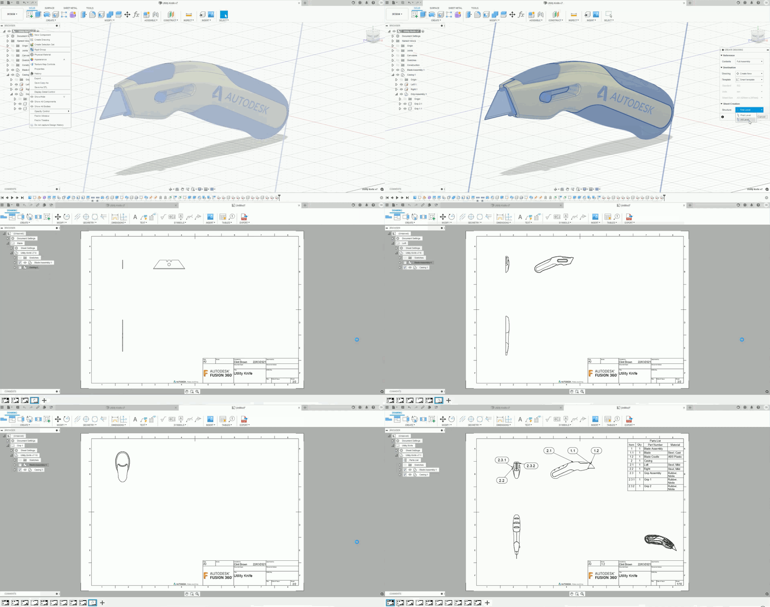
You told us that you loved smart templates but wanted more. We listened and expanded our Smart Template technology to include sub-assembly support.
Smart templates support “All Level” assemblies, which makes drawing creation even faster than before. The handy video below shows the difference between “First Level” & “All Level” sheet creation.
The user experience team leaned heavily on user research to inform the new design. As a result, commands are now more discoverable and grouped more logically. Commands, new icons, and better tooltips are also in more logical groups.
In April, we launched the Manage Extension, and the drawings team made sure that you could add Manage extension properties to your title blocks and parts lists.
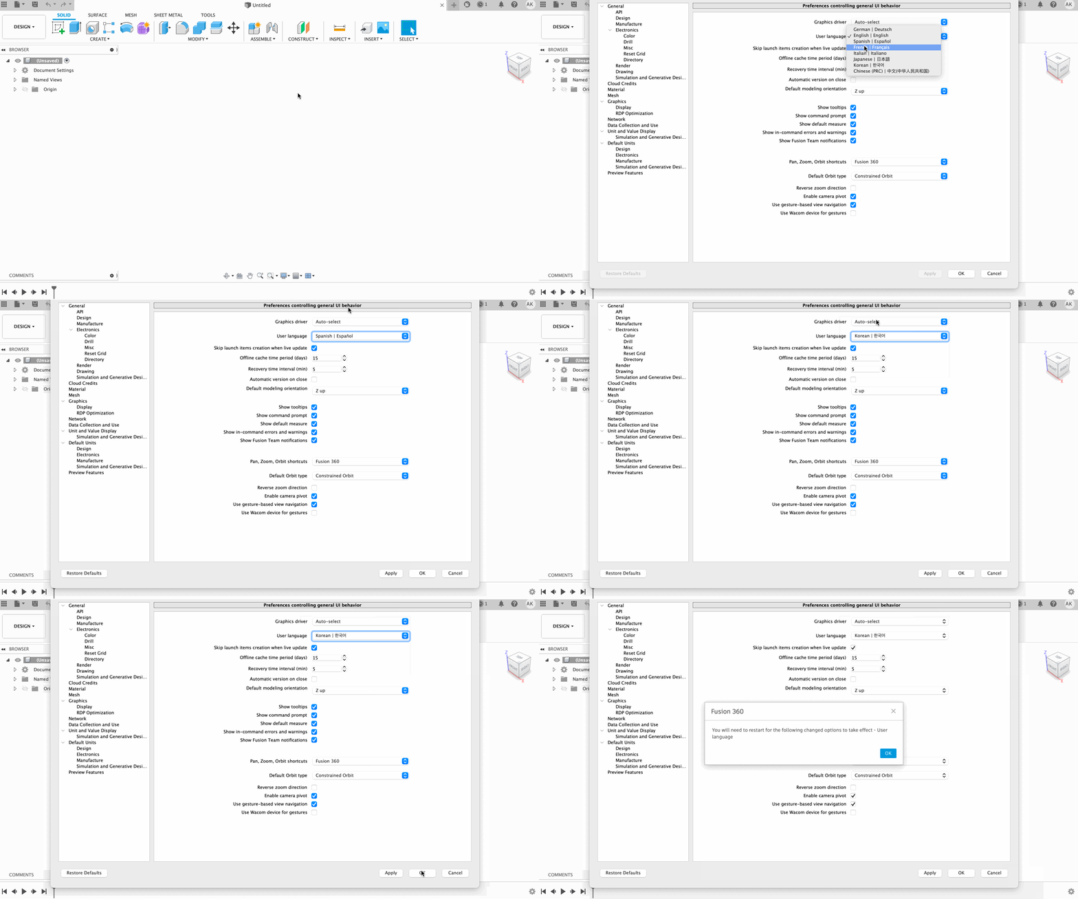
Ahora hablamos español. 우리도 한국말을 해요.
Similar to how you place your projected views with a Checkmark button to confirm your placement, we’ve now extended that checkmark experience to other drawings tools. The list includes Surface Texture, Feature Control Frame, Datum ID, Welding Symbols, and Taper and Slope Symbols. This feature lets you quickly confirm where you want to place your symbols in context to the placement itself while reducing overall mouse travel.
Grips in drawings are now more aligned with the modeling environment. Not only do they look better, but we’ve removed the redundant grips, too, making the interface cleaner.
Ever wanted your hidden lines to be really thin? You now have more control over line widths.
You told us that you wanted the ability to change the size of balloons and other objects. Text Height Groups gives you more control over text heights for various drawing features, including balloons, dimensions, notes, and more.
There’s more to come; our team works tirelessly to build the features you need to document your designs fully. Want to know what’s next? Check out our public roadmap for more information about what we’re working on, and check out our most recent Drawings update here.
We intend to make Fusion 360 the number one CAD/CAM choice for design and engineering professionals. Our user base continues to require more depth with solid and surface modeling capabilities, design automation, support for large assemblies, detailed sheet metal designs, weldments and frames, customizable libraries of components. Our goal is to continue to meet you where you need these tools to be. We’re also working on groundbreaking features that will redefine your expectations of CAD modeling. We have to do both — provide a familiar environment so you can get the job done and provide enough differentiation that it’s better than what you’re using today.
Thanks for tuning in to this design and engineering update as part of Fusion 360 Development Update Week. Check out the rest of Fusion 360 Development Update Week here:
Welcome to Fusion 360 Development Update Week
Collaboration & Data Management
Manufacturing


By clicking subscribe, I agree to receive the Fusion newsletter and acknowledge the Autodesk Privacy Statement.
Success!
May we collect and use your data?
Learn more about the Third Party Services we use and our Privacy Statement.May we collect and use your data to tailor your experience?
Explore the benefits of a customized experience by managing your privacy settings for this site or visit our Privacy Statement to learn more about your options.