Learn what the Fusion 360 team has worked on in the manufacturing space as part of Fusion 360 Development Update Week.

Welcome to Fusion 360 Development Update Week
Our quarterly Fusion 360 Development Update Week gives you an inside look at what we’re currently working on and offer a sneak peek at upcoming projects in our pipeline. During each Dev Update Week, we’ll publish separate articles dedicated to Design & Engineering, Manufacture, Usability, Collaboration & Data Management to give you a thorough picture of how we plan to develop each sector. These updates come straight from the source—our product team—the Fusion 360 team members working hard daily to bring you new features and improve existing workflows. Without further ado, let’s dig into the latest Fusion 360 Development Update Week Manufacturing edition.
Simulation, Machines and Post Processing

Machine simulation
Simulation is fundamental to CAM programming; it allows users to detect any potential issues when running the program. This year, we enhanced Fusion 360 simulation capabilities to enable users to simulate a digital representation of their machine directly inside the simulation environment in Fusion 360. The machine simulation preview is just the first step in our simulation journey. Our teams are now focusing on delivering collision checking for the machine simulation options inside of Fusion 360.
Machine Building
From the start, our goals have been focused on making machine simulation available to everyone so that you can ensure your tool paths are safe before running them on your physical machine tool. With that in mind, one of the most significant barriers to entry with machine simulation is getting an accurate representation of a real-life machine configured. With our preview release of machine simulation, we also released a preview of machine building, which aims to reduce this barrier to entry. The machine builder allows you to take a Fusion 360 model of your machine and fully configure it in machine simulation.
Machines
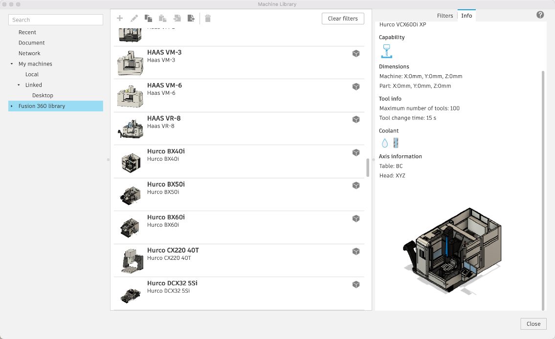
To help get users up and running quickly, we released a free machine tool library featuring configured and set up machines for post processing and machine simulation. To use these, users can select their desired machine from the machine library. This machine library is constantly expanding, and these machines are updated independent of Fusion releases, so keep an eye out for machines that may be useful to you!

Section Analysis
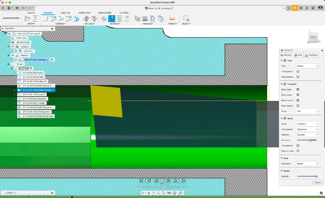
For users working in areas that can be difficult to see in simulation, we have good news. The section analysis options now work directly inside the simulation environment, and it does not just section the model. It also sections the stock so you can interrogate the moves that were previously out of view.

Tolerances
Previously simulation would be undertaken using an in-built tolerance optimized for speed and accurate results. However, this in-built tolerance did not work as expected in all cases, and users would sometimes see leftover material where they already removed material. In response, we have implemented a quality slider that gives users control over the accuracy of a simulation. Increased accuracy impacts performance, so it is important that users have control directly in the simulation environment.

Post processing with NC programs
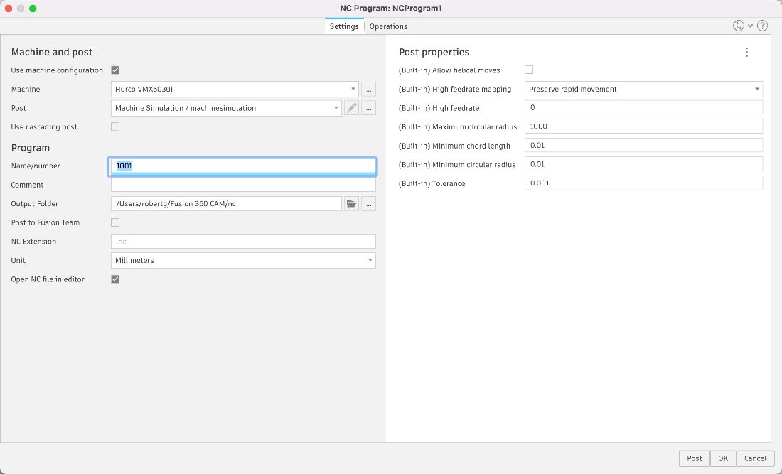
Users used to get mixed experiences when post processing based on what operation system and option they chose inside Fusion 360. The new unified post processing option uses the improved NC program dialog for post processing, bringing more functionality such as; post and machine management, post processing to Fusion team, and post processor property grouping.

Turning

Turning Tool-paths
Toolpaths are the foundation of any good CAM software; it’s why we decided to rebuild our algorithms for turning toolpaths to keep up with the demand of precision and control that a lathe programmer requires. Cycle time is everything for a high production environment, and creativity produces the best results in the most efficient way possible. This mix of creativity, control, and precision is what we have brought to our new Profiling toolpaths this year. Grooving tools in profiling strategies, grooving tools in threading strategies, more robust ways to calculate material removal like Even depth of cuts on randomized geometry. We continue to invest in this area as our top priority. We have been working behind the scenes to expand the new toolpath algorithm for turning into Grooving toolpaths. We are incredibly excited to bring some significant enhancements for Grooving in subsequent releases.
Turning Tools
Earlier this year, we released a survey to the community to understand where we lacked in the desired workflow. Based on the results, we decided to ramp up on our contribution to lathe tools, starting with minor bug fixes and additional features like DOC presets. Then, we pushed into other compensation points for grooving, proper left/right-hand configurations, and a better experience geared toward creating Lathe tools. Expect a lot more turning user improvements to come to tools over the next year.
Material Control Processes
Over the last six months, we spent some time deep-diving into what it means to support dual spindle lathes/turn-mill machines properly. It comes down to non-tool-path part handling strategies. We want users of all skill levels to feel comfortable programming these machines and utilizing them to their full potential. For this reason, we decided to work on the existing experience of part handling inside Fusion. The first thing needed for users was to expose was a Secondary Spindle Pull strategy to combine with the Secondary Spindle Chuck and Secondary Spindle Return strategies offered for Part Handling. We do plan to rename these in the future to clarify their uses better. After delivering the missing pieces to the individual processes, we plan to package these individual moves into templated processes.
Associative Workflows for Lathe Programmers
One of the unique pieces to Fusion360 is its ability to be an associative integrated CAD/CAM system. This strategy will define how we choose to build technology into the product. However, traditional CAM software for turning has historically “thrown out the model” and worked off an extracted wireframe profile. Our focus is to deliver a solution that works directly from the solid model so that you will not have to abandon the benefits of automatically capturing design changes in your toolpaths. A lot of the work is behind the scenes to keep up with this demand, but we are incredibly excited to unveil some recent projects that double down on this methodology soon.
Additive Manufacturing

Additive manufacturing or 3D Printing is not a single process, nor is it as simple as the plug-and-play we come to expect from 2D printing. So, back in 2019, when we released the first set of additive manufacturing capabilities for the Metal PBF (powder bed fusion) process, we knew that we were starting on a long journey. In 2020, we rolled out support for another Additive Manufacturing process and enabled the slicing of models and generation of toolpaths for certain desktop FFF (fused filament fabrication) printers. In 2021, we continued improving our capabilities and the workflow for both processes and introduced new ones.
Support for New Machines
New Additive Build Extension Machines
For the Metal PBF process, Additive Build Extension subscribers can now create additive setups using a new set of 3D printers from SLM Solutions and Aconity3D via the machine library.
New Machines for All Fusion 360 Users
For the FFF process, Fusion 360 users can now create Additive setups using a new set of 3D printers in the machine library from popular brands such as Creality, Geeetech, Alfawise, Makerbot, Flashforge, and BCN3D.
Free Additive Manufacturing Apps
We also released a free App on the Autodesk App store to connect Fusion 360 to Ultimaker Digital Factory. With this App, Fusion users can log in to Ultimaker Digital Factory, create new projects and upload their Additive setup to those projects, all within Fusion 360, streamlining their Design-to-Print workflows. We also included some FFF-specific features, such as the ability to print a temperature tower to dial in print settings for a certain printer/material combination. Additionally, we added the option to slice models in vase mode to print aesthetic and seamless 3D objects while saving material and time.
With another free App from the Autodesk App Store, Fusion 360 users can create an Additive setup for their MJF (Multi Jet Fusion) printers from HP and transfer that setup to the HP Smart Stream software for printing.
Metal PBF Simulation
We also released the capability to simulate the Metal PBF process directly within Fusion 360 as a tech preview. Historically such thermo-mechanical simulation capabilities were only available for our Netfabb Ultimate subscribers. Including this functionality in Fusion 360 not only allows users to simulate their process to detect and compensate for common print failures prevalent in metal 3D printing, but it also removes a barrier to entry for all organizations getting started with Metal PBF 3D printing.
SLA Printing Capabilities
During the first half of 2021, Fusion 360 users also gained the ability to prepare their 3D prints directly in Fusion 360 for an entirely new process, SLA (Stereolithography), using Formlabs printers. Fusion 360 now includes the SLA printers from Formlabs in the machine library, and users can orient their models, generate support structures, and create the specific files needed to print their designs.

We are excited about the second half of 2021, where we will continue improving the capabilities of Fusion 360 for the existing Additive Manufacturing processes and deliver support for entirely new ones.
Milling

The milling team aims to provide Fusion customers with a toolset that helps them optimize the capability of their 3, 4, or 5 axis milling machines. We strive to improve the efficiency of programming and machining their parts and increase confidence to run their toolpaths safely.
When we started this project several years ago, Fusion 360 already had a capable milling solution, but there were important gaps in its capability compared to the competition. We are successfully filling many of these gaps, and as we progress, we see a larger proportion of customers machining more complex, higher-value parts.
Here are some of the enhancements the Milling team has added this calendar year:
Tool Orientation
Before this enhancement, it wasn’t easy to define a non-orthogonal tool axis when no existing solid face was aligned to the desired orientation. This enhancement provides the user with complete freedom to easily set the tool-axis to their preferred orientation.

Steep and Shallow
People frequently use the Steep and Shallow strategy to machine freeform parts, often with a ball-nose tool. Machining flat regions with the same ball-nosed tool isn’t very efficient (lots of passes to get a small cusp height), and the surface finish on flat regions isn’t as good as we’d get with a bull-nosed tool. Additionally, the Steep and Shallow strategy now supports Lollipop and Slot milling tools. People frequently use Lollipop and Slot milling tools to machine undercuts on a 3-axis machine tool.

Toolpath Modification
Delete Selected Toolpath Passes or Segments
This feature complements our recent Toolpath Modification and allows users to select any undesirable moves on their toolpath and then remove them. There’s no need for costly toolpath recalculation. If their toolpath is 98% great, users can now make it 100% great by removing the undesirable 2%.

Keep Both for Toolpath Trimming (Machining Extension Feature)
We have enhanced the toolpath trimming feature. Keep Both (Inside AND Outside) is a new option in Toolpath Trimming. Before this, you could keep inside OR outside. Now you can keep both if you want. Keep Both is useful because you may want to separate regions of a toolpath for reordering or change the tool on a region of the toolpath. If you split a toolpath into two pieces, then you can reorder it, so the second part is machined before the first part (of the original toolpath). Alternatively, you can modify one of the regions to use a different tool.

Change Tool (Machining Extension Feature)
You may want to use a different length tool or a different tool holder on a calculated toolpath. The Change Tool modification can work on any toolpath, trimmed or not. The tool you change to must have the same cutting geometry, but the length or holder assembly can differ. The main benefit of this is that you do not need to recalculate toolpaths after a change. This option is typically used on large toolpaths with long calculations as it can be a fast way to change to a more suitable tool.
Mimic the PowerMill PAN, ZOOM, ORBIT View Controls
Experienced PowerMill users found it exceedingly difficult to control the Fusion 360 graphics view comfortably. Frustrating these users in the first few minutes of Fusion usage did tempt them to continue learning. Now, they can change their view preference to experience a very similar experience to what they have with PowerMill.

Timeline Enhancements
We have also improved the “toolpath Modifications” timeline. You can now select each item on the timeline. This feature enables you to see the result of a specific toolpath modification. The preview shows your edit performance, the edit result, and the region of the removed toolpath (if applicable).

Flat Finishing: New Automated Milling Strategy
We designed the new Flat Finish Strategy to give you higher efficiency in finishing flat regions of your design. This feature allows you to detect flat regions more accurately, providing greater efficiency on the machine and an improved surface finish. Flat Finish Strategy also recognizes open pockets and better uses entry and exit positions from outside the pocket as default paths. This feature allows you to extend tool life and maintain a consistent cutting engagement angle for better surface finishes. It also supports Avoid/Touch surfaces, has a fillet option that prevents damage to the tool when entering sharp, internal corners, and has a Machine Over Holes option.

Fabrication

At Autodesk University 2018, we first announced our commitment to bring Autodesk nesting technology to Fusion 360. In 2020, we introduced Previews for Advanced Nesting solution, Manufacturing Models, and the lightweight Arrange tool. Advanced nesting unlocked unprecedented workflows in Fusion 360. It became possible to complete the entire process for the first time — design parts, nest them, create toolpaths, and output NC code to drive CNC cutting machines — all within Fusion 360. We also included automatic nest reports and comparison tools for your quoting and estimation needs. In addition to being a prerequisite for nesting, Manufacturing Models provide a faster way to make manufacturing-specific edits without dirtying the original model.
Arrange Tool
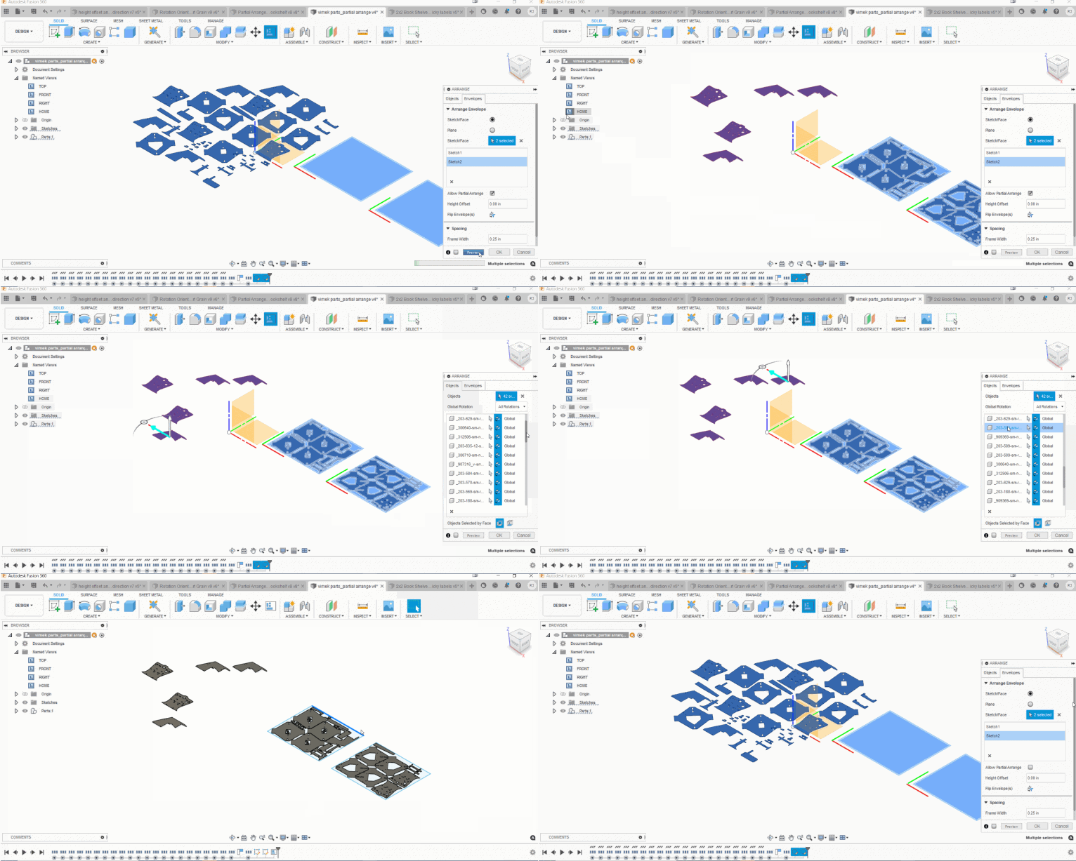
The Arrange tool makes it possible to quickly arrange components on a plane, sketch, or face without the additional complexity of advanced nesting. This tool is a history capture feature, so it offers full replay capability upon rolling the history marker backward and forward. After being a preview feature for four months, Arrange was included in the Fusion 360 Core offering for Commercial, Startup, and Education licenses.
Advanced Arrange (Preview Feature)

Nesting & Fabrication Extension
This extension unlocks advanced nesting capabilities to create optimized and associative multi-sheet layouts for your sheet metal and non-sheet metal parts in preparation for cutting on your CNC machines. It allows you to create nest studies from one or more documents to optimize material yield and minimize waste from flat raw material cutting operations. It also includes automatic material, thickness, and part quantity detection along with the ability to control part orientation and available stock sizes. Once the nests are generated, you may create setups, toolpaths, and NC code from Fusion 360 or simply export nest layouts as DXF files. Customizable nest reports can be saved and shared in PDF format. You can also multi-edit in Component Sources by CTRL + Select OR SHIFT + Select multiple Components and edit their Nest Parameters at once.
‘Finishing Overlap’ for 2D Profile Strategy
This option helps improve the consistency of the cut when manufacturing components with Laser, Plasma, or Waterjet machines. The overlap pass this generates will ensure a cleaner cut and eliminate the need for any secondary deburring/grinding operations.
We appreciate all the feedback and support you have provided along the way. It helps us continue improving Fusion 360 to make it a lovable solution for your Nesting needs. We have come a long way from where we started, and we’re excited about the journey that lies ahead.
Metrology

Industrial metrology is the application of measurement to manufacturing processes. It’s an essential building block for quality control, continuous improvement, and lights out manufacturing, metrology includes probing and inspection operations. We have been working to make workflows more seamless and to improve the consistency across Fusion.
Manual Inspection
Manual Inspection helps you to manage inspection activities using simple dimensional measuring instruments (such as calipers and height gauges) and pass/fail tests (such as a go/no-go gauge or visual check). If you have a ‘connected’ electronic dimensional measuring instrument (for example a USB or Bluetooth micrometer) the measurement results will be sent directly to Fusion 360, otherwise, you can simply type in the measured values using a keyboard.
Using Fusion 360 as the ‘single source of truth’ for inspection helps manage the results and ensures that dimensions are correct and up to date- if the model changes, the nominal dimensions will be updated to match.
Like the probing functionality, Manual Inspection allows you to create and measure the inspection plan, and create inspection reports, all directly in Fusion 360. It stores the measurement results, calculates the deviations between nominal and measured values, and allows you to create a graphical inspection report. You can create an inspection report using measurements taken by probing or Manual Inspection- or combine different types of measurements to create a single unified report- and save the report to Fusion Team or export it as a PDF.
Part Alignment
Part alignment enables part setting through probing on a milling machine- but for complex-shaped workpieces like forgings or castings, or for finish machining of metal additive parts. Simple part setting probing (‘Probe WCS’ in Fusion terms) is limited to basic geometry- it requires prismatic stock in the shape of a box or a cylinder, or a workpiece with prismatic features. Part alignment enables part setting for just about any workpiece you can physically measure with a probe. It uses ‘Inspect Surface’ functionality to measure the stock condition of free-form geometry and adjusts the position of subsequent milling toolpaths to optimize the distribution of available stock. If Part alignment determines that there is insufficient stock to machine the part, you can quickly make scrap or rework decisions with confidence.

Probe Geometry Inspection Report
Probe Geometry uses probing cycles from providers such as Renishaw or Heidenhain to measure critical features and dimensions and confirm that they are within required tolerances. The standard probing cycles (for example Renishaw Inspection Plus) can create a very basic inspection report in the form of a results printout on the CNC controller. The Probe Geometry Inspection Report functionality imports the basic results printout into Fusion, providing the additional benefits of graphical reporting and the ability to format and export the inspection results.
This is an important step in consolidating the probing capability within Fusion. Part Alignment builds on inspection technology to provide more sophisticated part settings. The Probe Geometry Inspection Report builds on probing cycles originally used for part setting to provide more sophisticated inspection reporting. Both improve overall capability and consistency.
Like the ‘Manual Inspection’ listed above, the Probe Geometry Inspection Report is another milestone in Fusion’s development as the ‘single source of truth’ for bringing together different inspection activities and creating unified inspection reports.

Match Color Conventions
This is an example of improving consistency across different areas of Fusion 360. The inspection reporting uses color to indicate areas of a model which exceed upper or lower tolerance limits so that you can easily see any areas with too much, or too little, material. Fusion 360 also uses color to show the stock condition during milling simulation, but historically the same color meant a different thing in these different contexts. The color conventions for inspection and stock simulation now match. You can choose between the two historic conventions with a setting in preferences, and Fusion displays a color legend to indicate which convention is in use.

Fusion 360 Development Update Week — There’s More!
Thanks for tuning in to this Manufacturing update as part of Fusion 360 Development Update Week. Check out the rest of this edition of Fusion 360 Development Update Week here:
Welcome to Fusion 360 Development Update Week
Design & Engineering
Collaboration & Data Management
See you at the next Fusion 360 Development Update Week!

