& Construction

Integrated BIM tools, including Revit, AutoCAD, and Civil 3D
& Manufacturing

Professional CAD/CAM tools built on Inventor and AutoCAD
4 min read
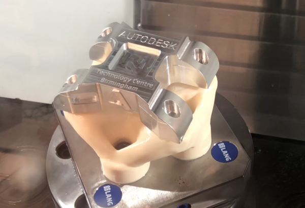
Following on from my “How To Machine” posts, today I’ll explain a slightly different process, how to machine a part using a 3D printed generatively designed fixture. Finding the best way to hold your part for machining can be one of the trickiest aspects of the process. Using Generative design within Fusion 360 helps make this much easier. For those of you who aren’t already aware of Generative design (you’re really missing out, follow this link to find out more!), it involves setting up obstacle and preserve geometry, so that the software can design the part for you. One of the manufacturing constraints users can apply allows for only 3D printable outcomes. In this case, this made the design and manufacture of my fixture much quicker, compared to traditional techniques. If you want to see some machining footage for this, follow this link.
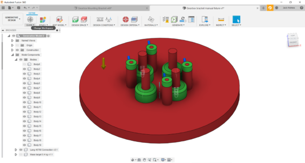
First, I created the design for my fixture to hold my part. For this, I used the Generative Design workspace. I set up the obstacle geometry, the areas where no material would be created, so that I could put bolts from underneath to attach the part to the fixture. Similarly, I created obstacle geometry, so that the fixture itself could be attached to a Lang plate. This meant the fixture could be located on the machine accurately, tightening only one nut. For the preserve geometries, the areas where material can be created, I set these as around the holes where the fixture would attach to the part. This was to ensure these holes were created with enough material around them, to work effectively. I then applied the necessary loads that the fixture would need to withstand during the machining process (I took these values from a previous Autodesk project).
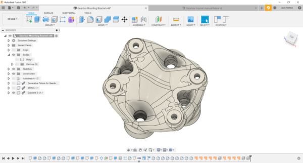
Generative design produces multiple results, each able to withstand the specified loads. This allowed me to select one that best suited my needs. I wanted to 3D print my fixture for rapid prototyping purposes. Therefore, I chose one which was lower in mass, so it would be easier and cheaper to print. I could be confident that Fusion 360 gave me a design which, although lighter, would meet the requirements. The image below shows the fixture that I chose. I then printed it on the Stratasys Fortus 380mc in the Birmingham Technology Centre. The material I chose was an ASA (Acrylonitrile Styrene Acrylate) polymer, with each layer 0.33mm high. The overall printing time was around 7 hours per fixture. Not bad at all considering how long it normally takes to produce fixtures with traditional manufacturing methods!
Another benefit of using a generatively designed fixture was that I could do most of the machining in one setup, even though I programmed several 3+2 operations. However, I still needed to drill holes on one side of the aluminium block, to attach it to the fixture. Therefore, for this, I used a Lang vice. This tool allowed me to hold the material with just 3mm of clamping, and place it back within a 5 micron tolerance. This makes the process extremely reliable and repeatable. For the second setup I then used my generatively designed fixture, and ran the remaining toolpaths just with this as my holding mechanism.
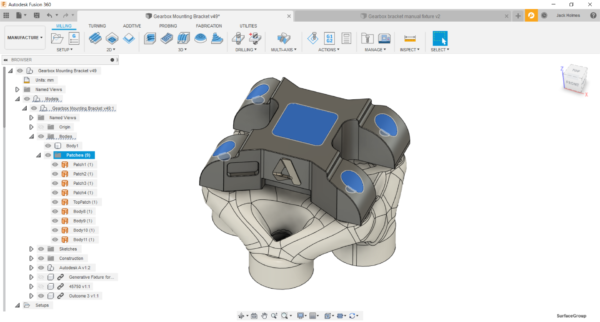
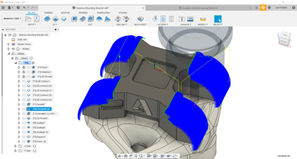
I used the 3D Adaptive Clearing strategy to rough most of the material away. This allowed me to use the full cutting length of my 12mm End Mill, while maintaining constant tool load and engagement angle. This is much better for tool life and clears material much quicker than traditional roughing. Another aspect worth mentioning is that I had to create patches over certain areas of the model I didn’t want the tool to enter during the roughing process. This is a major advantage of using an integrated CADCAM system, as I could quickly add these on to simplify my programming. You can see these patches in use in the image below.
I used multiple strategies to finish this part, as there were many different features on it. One of the main areas that required detailed finishing were the “feet” of the part. For these, I used a Parallel toolpath, with an 8mm ball nose and 0.1mm stepover. This gave a great surface finish without the need for manual polishing.
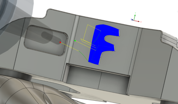
For the A and F symbols, I used Scallop with a 3mm ball nose. Even though these were located on the side of the part, I could easily program them using Tool Orientation. This option makes it very easy to create 3+2 toolpaths in Fusion 360. I only had to activate the Tool Orientation checkbox, pick my Z axis directly off the CAD and I was all set. As we have a trunnion on the Haas VF2 I machined this part on, carrying out this and other 3+2 operations was very straight-forward. If you want to know more about Tool Orientation, you can read this post.
The overall machining time for this part was around 2 hours, but the entire process, that would have taken way longer, was sped up by being able to use a generatively designed fixture that could be printed quickly in-house. Fusion 360 integrated CADCAM made the whole design and manufacturing workflow quick and seamless, as it was easy for me to switch between the Generative, Design, and Manufacturing workspaces at each stage. If you want to give this a go, but haven’t tried out the software just yet, you can download a free trial at this link.
By clicking subscribe, I agree to receive the Fusion newsletter and acknowledge the Autodesk Privacy Statement.
Success!
May we collect and use your data?
Learn more about the Third Party Services we use and our Privacy Statement.May we collect and use your data to tailor your experience?
Explore the benefits of a customized experience by managing your privacy settings for this site or visit our Privacy Statement to learn more about your options.