Following on from my “How to Machine” posts, today I’ll explain to you how to machine a Chess Piece using Fusion 360.

If you haven’t read the previous posts of these series, you can take a look at the links below:
- How to Machine a Steering Wheel
- How to Machine a Spider Plate
- How to Machine a Wheel Hub
- How to use a generatively designed fixture to machine
If you want to see some great footage of the machining process, you can watch this 1-min video.
Material and design considerations
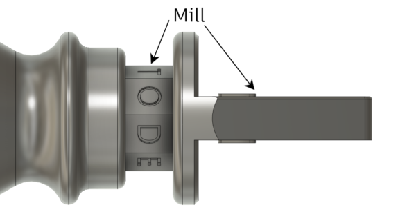
The Chess Piece was machined out of a fairly standard grade of Aluminium, 6082. The shape of the part made it a perfect fit for a turning machine with milling capabilities. In fact, I knew I could turn most of the main body, but I also knew I would have needed to mill the octagon shape and the Autodesk logo at the top, as you can see in the image below.
Hence, I chose to manufacture the part on a Mazak Integrex i-300S, a multi-tasking machine in the Birmingham Technology Center.
How to Machine a Chess Piece: Setup 1
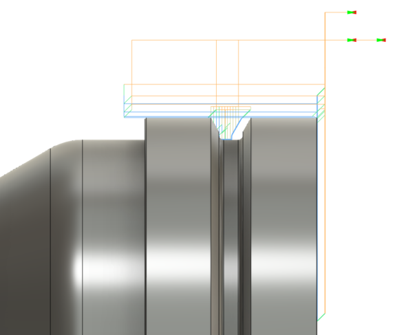
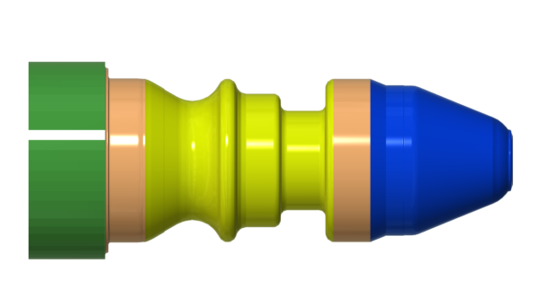
The Mazak Integrex i-300S has 2 spindles, meaning I knew I could machine the component in 2 setups. The only extra consideration to make is that all the milling work had to be done on the main spindle. Therefore, I decided to machine the bottom of the Chess Piece first, on the sub-spindle. I only ran three toolpaths on this Setup, respectively to face the part, turn the bottom profile and machine the groove. You can see the three toolpaths in the image below.
How to Machine a Chess Piece: Setup 2
The rest of the work was all done during Setup 2, on the main spindle. For this, I held the component with some soft jaws, machined based on the base diameter I had just turned in Setup 1. In Setup 2, I first faced the excess material, then I turned the profile and the grooves. Once I completed the turning operations, I started working on the milling toolpaths.
I used an Adaptive Clearing strategy to rough most of the material from the sides of the Autodesk logo. I then used a combination of 2D Contour, 2D Pocket and 2D Chamfer strategies to finish it. 
The next step was to machine the octagon shape where we had to engrave the word “Autodesk”. To do so, I created a circular pattern with eight 2D Pocket toolpaths, using a 10mm End Mill. The next thing to do was the engraving on the octagon. To do this, I used a 6mm spot drill. I then used the same tool to machine the chamfers on the “A” logo. I know it may sound unorthodox to use spot drills as engraving and chamfering tools, but they tend to be cheaper and more easily available than engraving/chamfering tools.

Conclusion
The overall machining time was around an hour per part. Some extra work was needed in between Setup 1 and 2, as the datum location had to be changed from the bottom face to the top of the Autodesk logo. As we ended up making around 40 chess pieces, we tried to minimize the cycle time as much as possible. Fusion 360 turning and milling tools made the whole manufacturing process quick and seamless. If you want to give Fusion 360 a go, you can download a free trial at this link.
I hope this post helped you learn more about how to machine a Chess Piece using Fusion 360. Stay tuned for more “How to machine” posts!