As part of our “How to machine” series, in this post I’m going to explain how to machine a steering wheel mould using the integrated CAD and CAM capabilities of Autodesk Fusion 360. If you have not had the chance to read the previous posts of this series, you can access them by clicking on the links below:
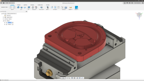
Setups
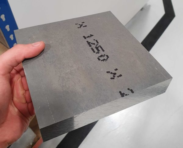
The starting point for this part was the raw block of material you can see in the image below. In this case I went for Aluminium 6082. I decided to machine this component on a DMG Mori DMU 60eVo linear, in the Birmingham Technology Centre.
The next step was to decide which side we would have machined first. The most sensible option was to work on the top first, which you can see on the left-hand side of the image below.
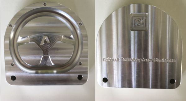
In fact, it makes sense to remove most of the material during the first setup, keeping tool wear in mind. In addition, choosing to work on this side first, ensured we could minimize vibrations even with relatively high feeds and speeds in the areas that needed most of the work.
Work Holding
Like for most other parts I machine, I used a Lang vice to hold the billet. This tool guarantees reliable and vibration-free holding, needing just 3 mm of material to clamp on. Lang vices also allow for re-alignment of a component within a 5-micron tolerance. This makes processes highly repeatable, compared to more classic holding mechanisms.

For Setup 1, we used the crimp mechanism, fully aware that it would leave marks on the sides of the partly machined component. For Setup 2 instead, we set up the parallel jaws, as we, obviously, did not want any marks on the finished part.
Given the geometry of the part and the versatility of the Lang vice, I did not have to think of a fixture, as I did not need one to fully machine the part.
Roughing
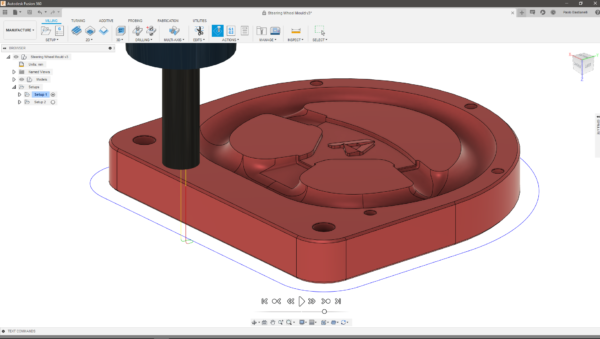
During the first Setup, the main area to rough out was the concave surface the makes the bulk of our steering wheel mould. Whilst I would normally use flat or bullnose end mills for my roughing operations, in this case I went for a combination of 2D Adaptive Clearing with an 8mm Ball tool. This way I managed to avoid running any semi-finishing toolpaths. These would have been required if I chose a flat tool to machine a concave region, as there would have been much more material left after the clearing passes.
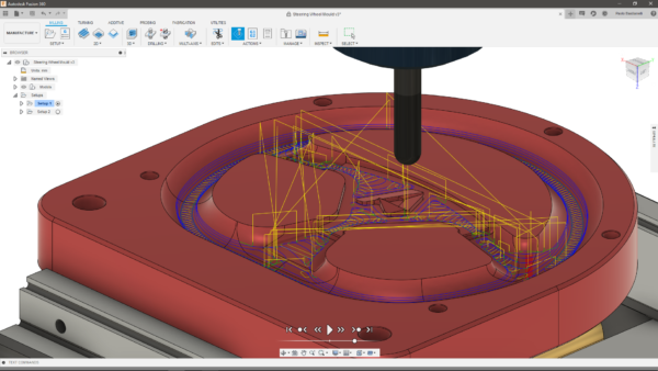
For the outer shape, we used a 16mm End Mill. As the stock we ordered was only 26mm in height, we managed to work our way around the part with a single pass. By maintaining both spindle speed and feed rate quite low, we got an excellent surface finish on the outside without running any finishing passes. For an outstanding result, always try to keep your tool as short as possible, to improve rigidity!
Finishing
For most of the concave regions, I used a 4mm Ball tool for my finishing toolpaths. As I mentioned above, there was not much material left after the roughing on the main mould region. The stepover I used for this toolpath was 0.2mm, to get a great surface finish without the need for polishing.
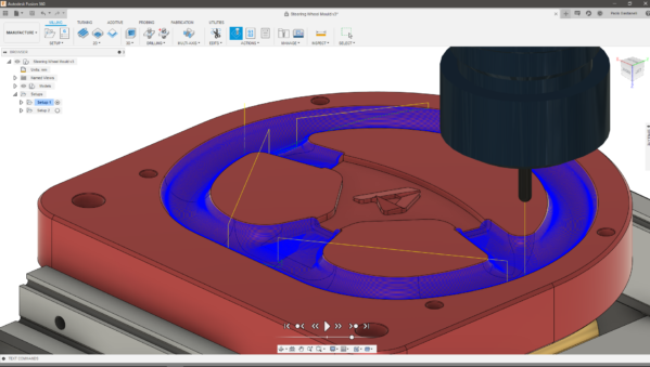
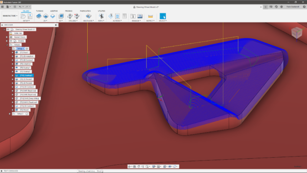
However, there was still quite a lot of programming to do to finish the Autodesk “A”. For the inside of it, I used a 2mm End Mill with a 2D pocket toolpath. For the freeform shape of the A though, I used a 2mm Ball tool in combination with a Scallop toolpath. I went for a very fine stepover for this strategy, only 0.05mm, to get an excellent finish.
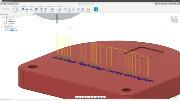
For the engraved text on Setup 2, we used the same 2mm Ball tool, this time with a Trace toolpath, projecting the text on the flat back of the part. I find Trace an excellent toolpath in terms of ease of use and overall output quality. You should definitely use it more if you do not already!
Finally, for the chamfers on the holes and around the part, I used a 2D Contour toolpath with a Chamfering tool. Chamfering sharp edges is standard practice in manufacturing, as it minimizes risks of injuries when touching the part.
Conclusion
The overall cutting time for the component was around 1 and a half hours. As you may expect, I spent most of this time on Setup 1, as Setup 2 only accounted for 15 minutes of the total cutting time.
Fusion 360 integrated CAD/CAM tools made the whole design and manufacturing workflow quick and seamless, as it was easy for me to switch workspaces when needed. If you want to give this a go, but haven’t tried out the software just yet, you can download a free trial at this link.
I hope this post helped you learn a bit more about how to machine a steering wheel mould. Stay tuned for more “How to machine” posts!