This post is also available in: 日本語 (Japanese)
Improve product compliance and performance, reduce costly physical PCB testing and prototyping, and accelerate development with the Fusion Signal Integrity Extension powered by Ansys.
High-speed PCB design can be challenging as it requires multiple considerations, including trace width, PCB material properties, ground plane clearances, adjacent geometric spacing, return paths, and more. Manual identification, verification, and correction of these constraints on any ECAD system can be a daunting and time-consuming task.
What is the Fusion Signal Integrity Extension?
The Autodesk Fusion Signal Integrity Extension, powered by Ansys, enables designers to analyze their PCB electromagnetic performance. With simple input parameters and configuration, engineers can select signals of interest for quick analysis.
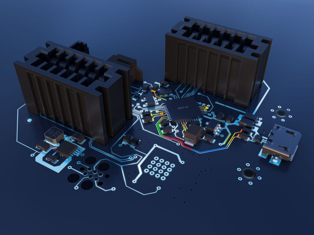
The results are rendered with a colored gradient, enabling designers to easily identify problematic signal paths and violations, allowing them to make design updates and mitigate signal impedance mismatches.
What are the benefits of the Fusion Signal Integrity Extension?
Ensure compliant smart products
Easily ensure your products’ high-speed, RF, and wireless capabilities meet your design specs and are compliant with industry standards, directives, and rules.
Reduce development costs
Minimize costly PCB physical testing and board re-spins with access to feedback on your design’s electromagnetic performance.
Get to market faster
Reduce the length of project timelines by reducing activities due to engineering change orders, multiple physical prototype PCB manufacturing, and physical EMC/EMI testing.
What’s available in the Fusion Signal Integrity Extension?
Simple configuration
With simple input parameters and configuration, engineers can select signals of interest for quick on-demand analysis.
Signal insights
Analyze your design to inspect parameters that characterize high-speed signals, such as propagation delay, trace length, impedance, and coupling.
Impedance matching
Manage and control the impedance for every transmission line throughout your board for a distortion-free and optimal high-speed performance design.
Visual violation flagging
Easily and visually identify any potential impedance or coupling issues with a superimposed color-coded overlay on your 2D PCB design.
Are you ready to take the headache out of high-speed PCB design with access to electromagnetic analysis capabilities, allowing you to create smarter products, faster and at a lower cost?
Ready to get started with high-speed PCB design? Try the Fusion Signal Integrity Extension for free today: