A common question we get asked about Fusion 360 is “What is the difference between creating a new work coordinate system and defining a tool orientation for a positional axis-move?”. I will separate this blog into two halves. In the first part, we’ll look at Work Coordinate Systems, or WCS for you Fusion 360 fans.
Work Coordinate System
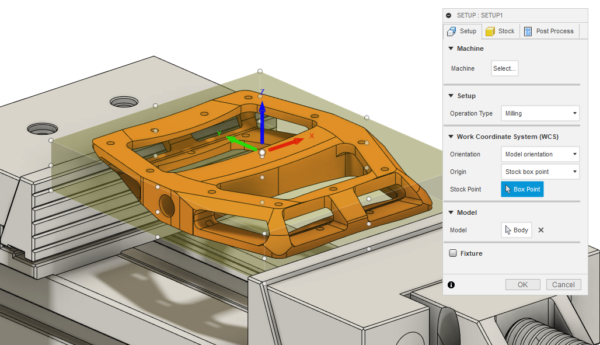
The Work Coordinate System is what you must define in your setup. This MUST match your reference point on the machine, such as G54, G55 etc.
If the Work Coordinate System and your G54 on your machine do not match up, when you output your toolpaths to the machine, the machine will be referencing your strategies to a different coordinate system. This means your toolpaths will be shifted by the distance separating your G54 and your WCS. A lot of people tend to use either the centre of the stock or a corner as their reference. This will make this a simpler and more intuitive process.
Tool Orientation
Let’s now look at the Tool Orientation functionality. As you may know, this can be found within many of the toolpaths within Fusion 360. The first thing to be aware of, is that this functionality will only work if you have 5-axis functionality on your machine tool. It sounds trivial, but it was worth mentioning just in case!
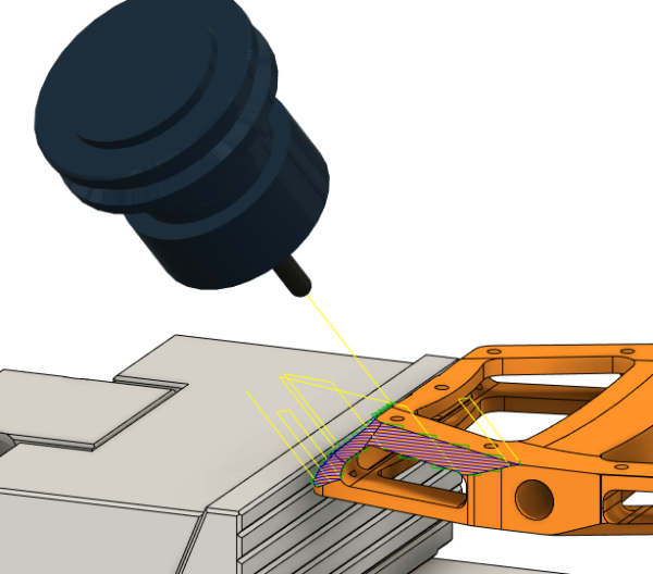
Tool orientation once turned on allows you to orientate your tool, so that you can machine your component or feature at an angle that differs from a 3-axis orientation.
Tool Orientation options
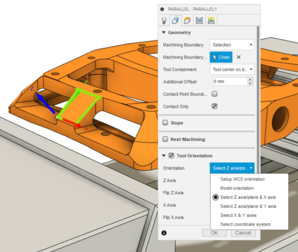
This functionality allows you to select the orientation in a few different ways.
- Setup WCS:
Your tool will align with the axis of the Work Coordinate System associated with the active setup. - Model Orientation:
Your tool will align with the axis of the Work Coordinate System associated with the active model. - Select Z Axis/Plane & X Axis:
This allows you to choose the Z & X axes yourself, using the model geometry. - Select Z Axis/Plane & Y Axis:
This allows you to choose the Z & Y axes yourself, using the model geometry. - Select X & Y Axis:
This allows you to choose the X & Y axes yourself, using the model geometry. - Select Coordinate System:
This allows you to align your tool with a User Coordinate System in the model. This option is useful if your part does not have easy-to-pick points or planes.
Each have their own advantages to them. However, I like the flexibility of selecting the Z, X or Y axis, as I can either use drawn wireframe from a sketch or the model geometry, such as the edges of my part, to align the axes.
Conclusion
The flexibility offered by this functionality is a great benefit. Being able to easily choose an orientation on a toolpath-to-toolpath basis can save you plenty of time, as you won’t need to manually orientate your component on the machine.
I hope this post helped you clarify the difference between the Work Coordinate System and Tool Orientation functionality. The best way to remember what they are is this: the Work Coordinate System does not change for a given setup, while you can use the tool orientation functionality whenever you need a different angle to machine a surface or feature.
Are you new to Fusion 360? If you want to try it out, you can download a free trial at this link .