As a CAM engineer, for the past 5 years, I have been using Autodesk PowerMill for most of my programming. However, I recently made the switch to Fusion 360 for programming my components and I want to share my experience. This post is going to give you a few tips on how to machine a Wheel Hub with Fusion 360, leveraging its integrated CAD and CAM capabilities. If you want to see some machining footage (who doesn’t love watching swarf flying off?) you can visit this link .
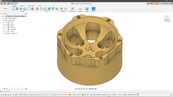
Setups
One of the first things any CAM programmer should always think of, when starting programming, is which side of the component they are going to machine first. This choice will also have vital implications when defining the work holding for subsequent processes, as you will see later in this post. I ended up choosing to first machine the side you can see on the left-hand side of the image below. The main reason for this choice was the presence on the model of two dowel holes and four tapped holes, all very useful for part positioning and holding during subsequent operations. I also realized that I could machine away most of the material during Setup 1, leaving me with few toolpaths to run during the following stage.
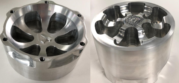
Work Holding
During the first setup, I held the billet using a Lang vice. This exceptional tool allows for reliable and vibration-free holding, even though it requires just 3 mm of material for clamping. This meant I could order the billet just slightly oversized, a significant reduction in size compared to the larger block of stock I had initially defined. Another great benefit of using a Lang vice is that, when removing the component and placing it back in the vice, it allows for part re-alignment within a 5-micron tolerance. This makes the process extremely reliable and repeatable, for example, if you plan on cleaning up multiple billets before starting to run your toolpaths on one of them.
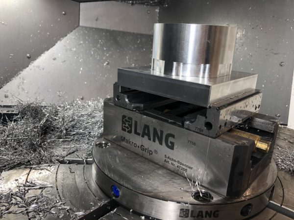
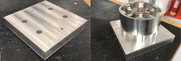
When I got to the point of running the toolpaths in Setup 2, I had to think of a fixture. In this case, it was easy to come up with a design, as I realized that a plate with six holes (two for the dowel holes and four for the tapped holes) would do the job perfectly. The tapped holes were used for screwing the part onto the fixture, whilst the corresponding holes on the fixture for the tapped holes were counterbored.
Tooling
Assuming you already specified the material you are going to machine (in my case, I machined the Wheel Hub out of Aluminium 6082), the first thing to do before ordering the correct tooling for the job is to analyze the part geometry, including the radii present on the finished component. For instance, using an 8 mm ball nose tool to machine a surface that includes a 3 mm radius would inevitably end up leaving too much material on the part, which in turn would result in the need for additional toolpaths to complete the programme.
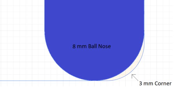
For the Wheel Hub, after analyzing the geometry, I ordered a 16 mm End Mill for the external roughing, so I could do it in one single pass, to reduce machining time. When I analyzed the radii on the part, the minimum (concave) radius I found was 5 mm, meaning any tool with a diameter below 8 mm would do the job well, leaving no unwanted material on the component after the finishing passes. At the same time, this tooling choice made sure I could avoid excess forces on the cutter due to the increasing tool engagement angle, improving surface finishing and tool life.
Feeds and Speeds
As mentioned in the first paragraph, I managed to machine away most of the material during Setup 1. This meant I could be quite aggressive during Setup 2, both in terms of feeds and speeds and in terms of stepover and stepdown choices. For instance, to machine the main cavity within Setup 2, I managed to push my 10mm End Mill at a spindle speed of 12000 rpm and a cutting feed of 5000 mm/min. For roughing, I used Adaptive Clearing, as it allows our tool to be under constant cutting forces by maintaining a constant engagement angle between the tool and the material. This resulted in a much safer and faster roughing process compared to traditional clearing toolpaths.
Seamless Integrated CAD/CAM Workflow
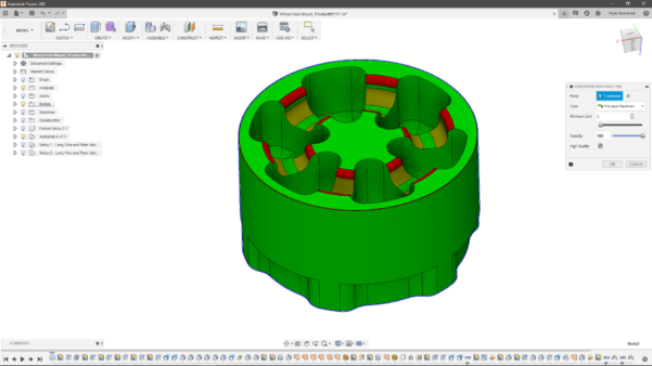
One thing that many programmers tend to overlook is how much time they spend switching between their CAD and their CAM software when they need to make modelling changes for their part. Fusion 360 is a massive help in this case, as it allows for a simple, seamless workflow between the modelling and manufacturing environments. In my case, I had to create several free-form surfaces to “deceive” my tool to stay on the component during my finishing toolpaths, as you can see in the example image below.
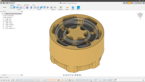
Doing this in Fusion 360 only took a couple of minutes of easy and painless work, whilst doing it in a more traditional manner would have involved switching back to a CAD package, making the edits and exporting the component back to the CAM package (hoping the changes wouldn’t invalidate the rest of the program!). Having an integrated CAD/CAM tool is also a massive help when designing the fixture for your part, as everything can be done within the same environment and any subsequent modifications can be performed without having to switch software halfway through.
I hope by now you will have learnt more about how to machine a Wheel Hub with Fusion 360. The part was programmed without using the advanced tools available within the Manufacturing Extension (you can find more info on this topic here). If you are excited about trying Fusion 360 (who wouldn’t be?!), you can download a free trial at this link.