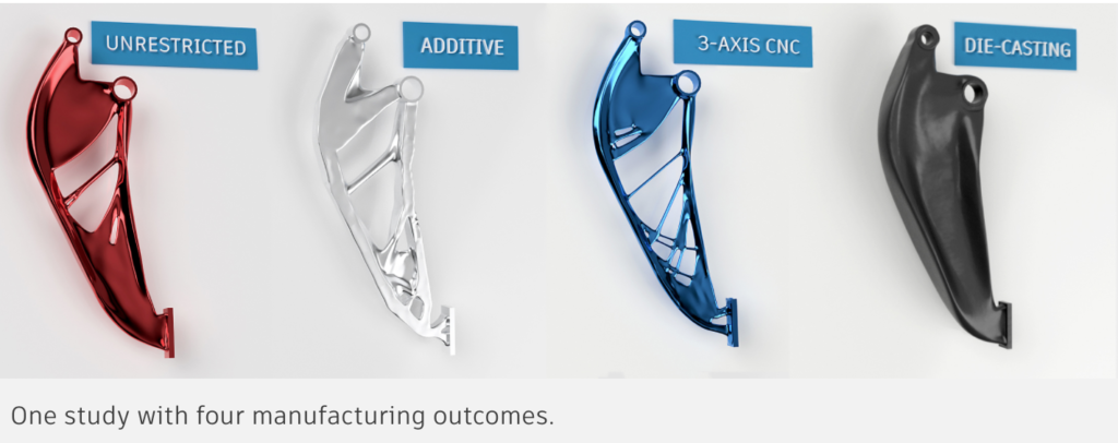
Generative design helps us seek out new ways to solve engineering and product design problems. It helps us explore what lies beyond traditional design boundaries — especially when reducing weight, achieving high stiffness, and using minimal material are important goals.
Many people still see generative design as a tool for creating designs that can only be produced using additive manufacturing. While that may have been true originally, it is no longer the case. Generative design can optimize solutions suitable for many manufacturing techniques.
Specifically, generative design can deliver manufacturing-ready designs for 2D cutting, 2.5-axis, 3-axis, 5-axis CNC machining, and even die-casting. Consider the results of this generative design study. All are valid design options, each tailored to a specific manufacturing method. And all were produced from a single set-up in generative design.

That breadth of capability is interesting because additive and subtractive techniques are often seen as mutually exclusive. As we will see here, fusing additive and subtractive methodologies with generative design can be very beneficial.
Additive manufacturing is often restricted by the fact that unsupported overhangs are not only undesirable but may not even be possible.
With Fused Filament Fabrication (FFF) 3D printers, for example, it is now possible to use material filaments densely loaded with metal powder carried within a polymer binder. Using these materials, parts can be 3D printed on desktop machines and then subsequently put through catalytic de-binding and sintering processes to get to a final metal part that is very close to 100% dense.
But the material I wanted to use, BASF Forward AM Ultrafuse 316L, has no compatible material for removable support, so overhangs are not possible. (Overhanging areas can also cause issues with part stability during de-bind and sintering.)
To solve this problem, I used the 2.5-axis CNC machining constraint in Fusion 360. When specifying the manufacturing objectives for 2.5-axis CNC machining in the generative design study setup, you can define the minimum tool diameter. Normally, you would specify your tool’s actual dimensions, but the software does not limit you to real-life tools. If you need to create a solution for FFF 3D printing, you can choose 0.4 mm to represent the diameter of material extrusion from the nozzle.
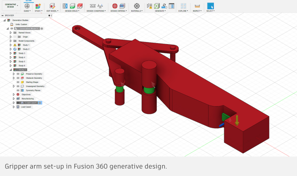
Here is a study I ran for the design of a gripper arm:

I set up the study and included the 2.5-axis constraint knowing I would use additive manufacturing. I set the tool diameter at a fairly modest 2 mm (even though a 0.6 mm nozzle would be used) and set the wall thickness at 2.5 mm to provide a usable condition for 3D printing. The tool direction was set at Z to ensure no overhangs would be created.
This is one of the solutions generated, which looked worthy of further investigation. I exported this outcome and made only minor changes before 3D printing.

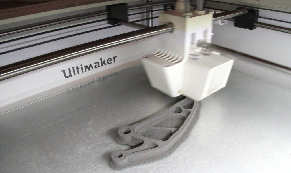
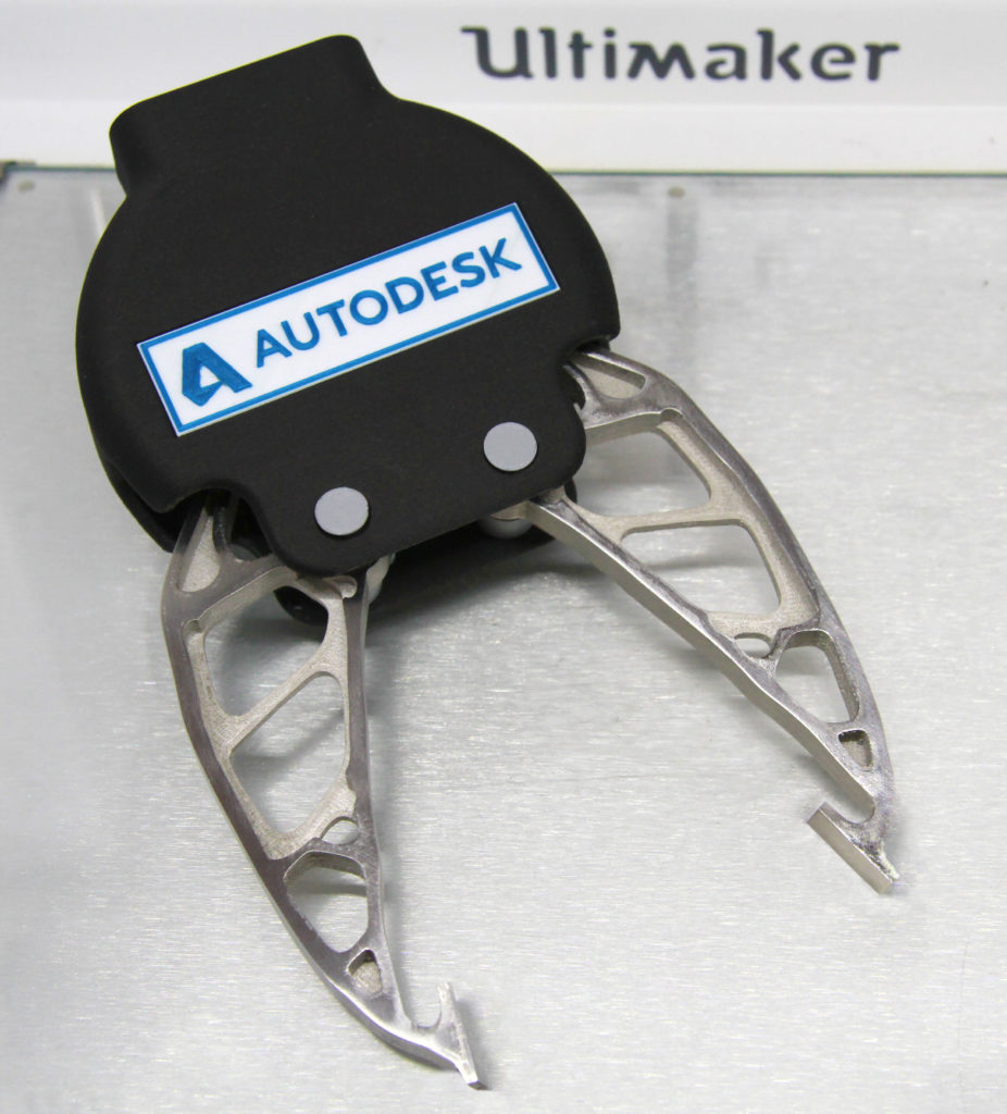
What resulted was a straightforward, support-free 3D print using Ultrafuse 316L on an Ultimaker S5 machine. These 3D prints were then put through the de-bind and sinter process to finish up with generatively designed 316L stainless steel part successfully manufactured with a desktop 3D printer.

So what are you waiting for? Open up Fusion 360 and become a “design explorer” using all the tools that generative design offers. See how you can combine additive and subtractive manufacturing objectives and discover the benefits of generative design today.
