In Part 4 of this series, we discovered what the patch command does, and when we might want to use it instead of loft. In Part 5, we’ll focus on fillets. We’ll learn the best way to set up a fillet, and we’ll find out what to do when they go wrong.
What is a fillet?
In real life, we create a fillet or round using a machine tool cutter to ‘soften’ the sharp edges of our products. The Fillet tool in Fusion 360 replicates this process.
The Fillet tool creates a set of tangent or curvature continuous faces that connect to the faces that meet the selected edges (read Part 1 of this series for a definition of ‘Curvature Continuous’).
Types of fillets
What do all fillets in Fusion 360 have in common? Let’s look at the types of fillets we can create.
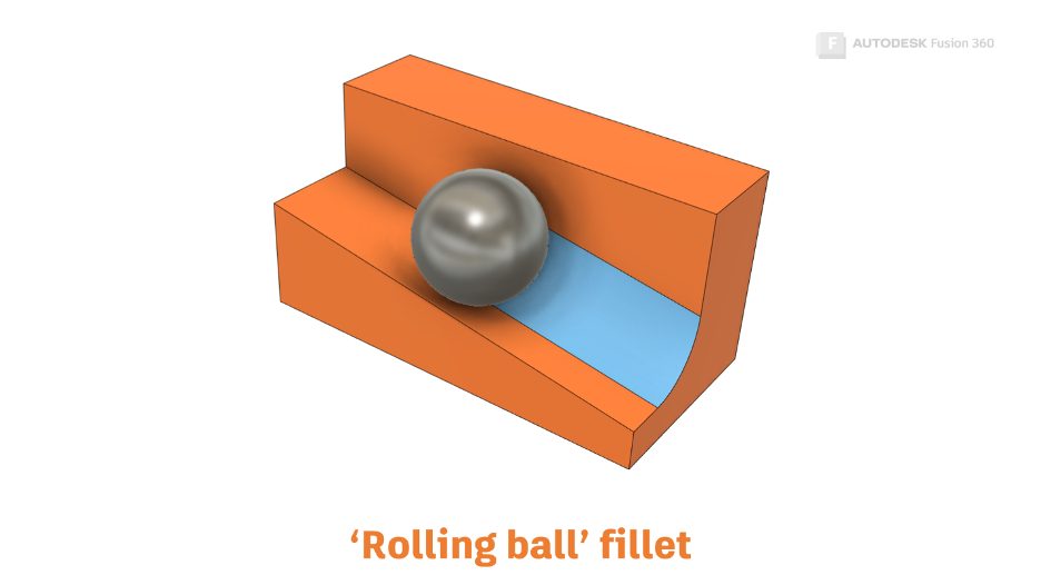
Rolling ball Fillets
Constant radius fillets have a regular cross-section. This method of calculating fillets is known as the ‘Rolling Ball’ method. You can imagine a ball being rolled along two faces that meet at an edge so that the ball is always tangent to the faces, with a new fillet (External), or round (Internal) face developing as the ball rolls along.
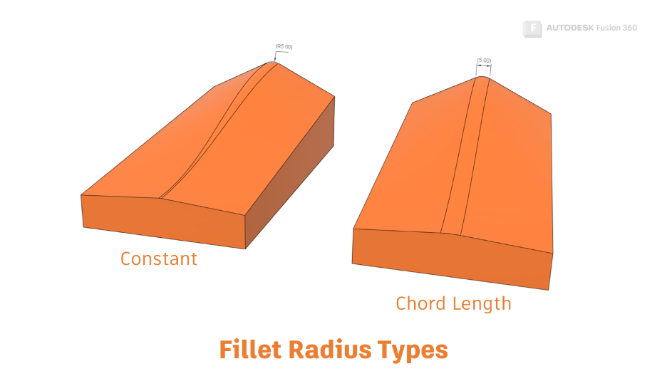
Chord Length Fillets
Constant Radius fillets have a consistent radius at any point along the selected edges. Chord length Fillets maintain the same distance across the chord of the fillet.
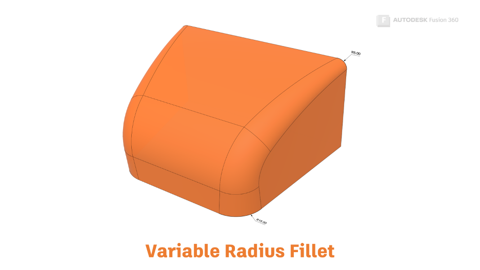
Variable Radius Fillets
Variable radius fillets allow the radius of the fillet or round to adjust at the start and finish of the selected edge, and at any number of points along the way.
What do all fillets have in common?
If you read the previous posts in this series on swept and lofted forms, you may have already guessed! Behind the scenes, Autodesk Shape Manager (ASM) uses the same algorithm that generates swept forms or centreline lofts.
In this case, the profile is calculated for you. The profile is an arc that remains tangent to the two faces that connect at the selected edge. We use the Fusion 360 interface to define an edge and a radius, and Fusion 360 passes this to ASM, which generates a swept or lofted surface and passes the result back to Fusion 360 to show on the screen.
What are the best practices for filleting?
The first piece of advice is to model your edge-consuming features, such as fillets and chamfers later in the timeline. This will help you avoid problems with projected geometry losing the edges that you have projected. An exception is when using the Shell command to create thin-walled components. In this case, you may have to fillet before the shell.
Break single fillet features into multiple fillets.
Although you can define one fillet feature that contains multiple fillets of different radii, it’s probably a better idea to create multiple fillet features. If you create one fillet feature containing multiple fillet definitions, and your fillet fails, it can be hard to know which fillet is causing the problem.
Creating fillets of the same size individually can also help your colleagues downstream. Often fillets are not needed for CAM programming. Creating fillets of different radii as separate features will make it easier to suppress fillets that aren’t needed in the CAM environment.
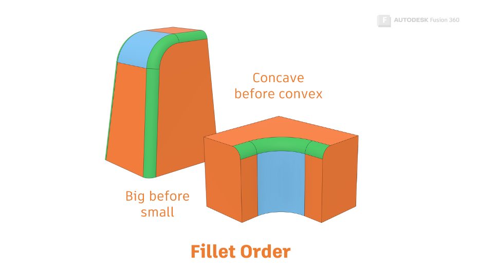
Big before small
Create the fillets with the biggest radius first, then follow up with fillets that have a smaller radius.
Concave before convex
Try creating your concave fillets before your convex fillets (Rounds). In many cases, you’ll find it doesn’t work the other way around.
Fillet failure tips
Automatic edge chaining
If you are filleting up to a complex junction. Try turning off ‘Automatic Edge Chain.’ This will allow you to pick each edge individually. If the individual edge you select doesn’t display a preview, it’s likely to be the problem.
Near tangency
Edges that are near to tangent may not fillet reliably. If ‘Tangent Chaining’ is on and the chain does not propagate across a vertex that looks tangent, you may have discovered a near tangency issue. A quick way to test is to start the fillet command and select the edge. Tangent edges cannot be selected. If you can select the edge with the fillet command active, it is not tangent.
The best fix is to roll back the timeline and adjust the original geometry to create a tangent condition.
Get Smart With Fusion 360 Series
Did you find this post helpful? Check out the other articles in this series:
3D Modeling Terminology
What Is a Sweep in Fusion 360?
The Secrets of the Loft Command
What’s the Difference Between Loft vs. Patch?
This article is based on an Autodesk University class. You can watch a recording of the class and download a handout that goes with this presentation from the Autodesk University website here:
7 Deadly Sins of 3D Part Modeling in Inventor & Fusion 360.