In Part 3 of this series, we learned the difference between Loft with Guide Rails and Loft with Centreline. In Part 4, we’ll learn the difference between Loft vs. Patch, and how we can apply that knowledge.
What is a Loft?
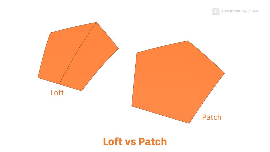
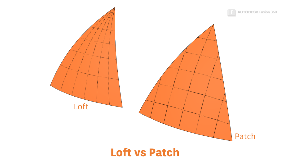
When we ask Fusion 360 to ask Autodesk Shape Manager (ASM) to generate a surface using the Loft command, ASM will create a four-sided surface. It will then ‘fit’ the surface to the geometry we have provided.
For this reason, Loft works well when creating four-sided surfaces. Loft also works pretty well when creating surfaces that have more than four edges. In this case, however, Loft will just divide the shape up into four-sided surfaces for us. This is why your Lofted surfaces will always have at least one visible edge.
What is a Patch?
The Patch tool also allows us to create surfaces from multiple profiles. The Patch tool can also ‘Warp’ surfaces, allowing us to set curvature continuity on its boundaries (Read Part 1 of this series for a definition of Curvature continuity).
A Patch is also a four-sided shape, but instead of fitting the patch to its inputs, ASM will trim the patch surface to the inputs.
When should I use Loft instead of Patch?
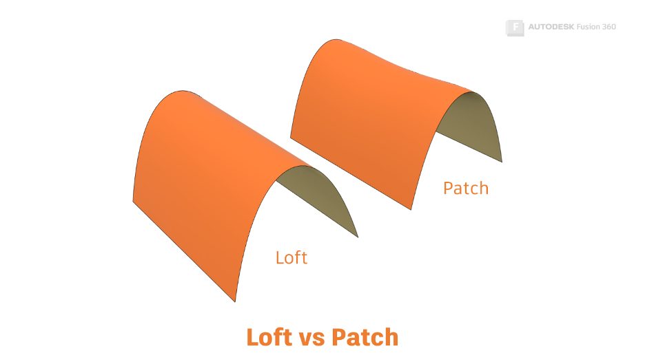
Loft is great for covering large areas. Loft creates a ‘ruled surface’, meaning the shape goes directly from one profile to another without dips.
When should I use Patch instead of Loft?
Patch is best used for surfacing a non-four-sided edge chain. Patch is the only tool that will fill a single entity shape (a circle!). It also has an excellent ‘Tolerance’ feature, meaning that the edge chains don’t have to join perfectly at the corners for the Patch tool to return a result.
Get Smart With Fusion 360 Part 5: Filleting Best Practices
Stay tuned for ‘Get Smart with Fusion 350. We’ll take a closer look at how the 3D modeling tools in Fusion 360 work under the hood. You’ll also learn what to do when your fillet operations fail.
Check out the other articles in this series:
Get Smart with Fusion 360 Part 1: 3D Modeling Terminology
Get Smart With Fusion 360 Part 2: What Is a Sweep in Fusion 360?
Get Smart With Fusion 360 Part 3: The Secrets of the Loft Command
This article is based on an Autodesk University class. You can watch a recording of the class and download a handout that goes with this presentation from the Autodesk University website here:
7 Deadly Sins of 3D Part Modeling in Inventor & Fusion 360.