In Pt. 1 of this series, we posed a challenging question – Have you created a sweep today? The answer is almost certainly ‘yes’. In Part 2, I’ll explain why.
When is a feature a sweep?
What do the following Fusion 360 3D modeling commands have in common?
- Extrude
- Revolve
- Coil
- Pipe
- Rib
- Web
- Hole
- Primitives (Box, Cylinder, Sphere, Torus)
- Ruled surface
- Sweep
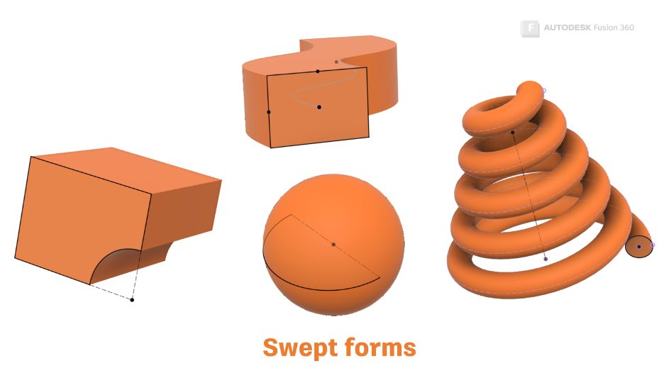
The answer is that they all create features with a consistent cross-section. This is known as ‘translation.’ The cross-section is translated along a path. In Fusion 360, this cross-section is called a ‘profile.’
Under the hood, ASM (the Autodesk Shape Manager) uses the same algorithm to create all these features.
The difference between a swept form created with the Sweep command and a swept shape created with commands such as Extrude or Revolve is that a Sweep path is explicit. We create it ourselves. The other commands translate a cross-section along an implied path. For example, an extrude path is implied as perpendicular to the sketch plane, whereas a revolve path is implied as an arc around the axis.
The path is implied by Fusion 360. Fusion 360 passes the Profile (cross-section) and the path to ASM, which generates a 3D shape. It then passes it back to Fusion 360 to display on the screen.
Therefore, I know you created a sweep today – even if you didn’t use the Sweep tool to create it!
What can I do with a sweep?
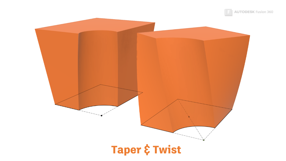
The one rule of sweeps is that they must have a consistent cross-section. However, we do have some additional controls for sweeps.
You can scale the cross-section (think ‘Taper’ in the Extrude or Sweep command), and you can rotate the cross-section (think ‘Twist’ in the Sweep command).
What can’t I do with a sweep?
The sweep algorithm accurately maintains a cross-section along a path, so swept forms can only have one profile.
How can I sweep between multiple profiles?
Well, you can’t. At least, not with the sweep command! If you need to create a shape using multiple profiles, you’ll need to use the Loft command.
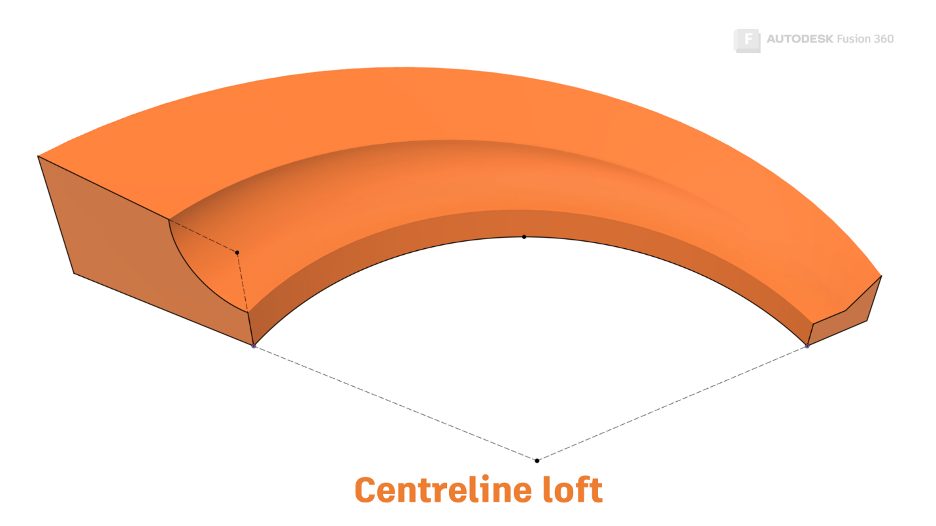
Loft with centerline
The ‘Loft with Centerline’ command uses a hybrid algorithm that can sweep multiple profiles along a path and ‘warp’ the shapes between the profiles simultaneously.
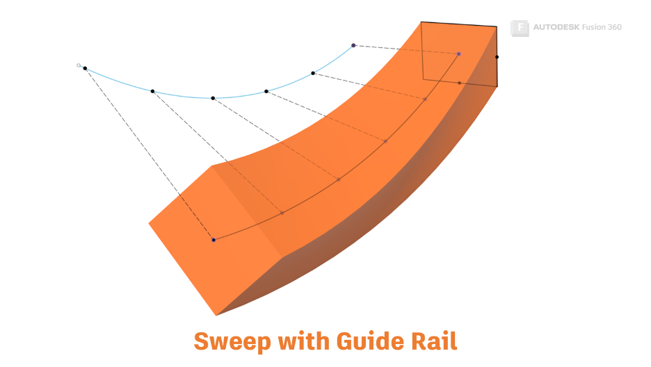
How does a guide rail control the shape of a sweep?
You can use guide rails and surfaces to control the rotation (twist) of a profile along a path. When sweeping a guide rail, imagine lines drawn between your path and your guide rail. As these imaginary lines rotate around the path, the profile will rotate with them.
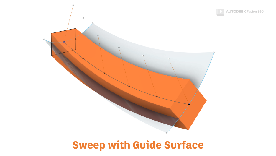
How does a guide surface control the shape of a sweep?
A guide surface is similar, but this time the twist is in relation to the surface normal. ‘Normal’ can be thought of as perpendicular to a surface.
When should I use a sweep?
Since a sweep must maintain a consistent profile, we can’t create sweeps that are curvature continuous to other geometry. For this reason, it’s usually a good idea to start with swept features (for example, extrude or revolve) as your base features. Then, use Loft or patch to create features that are curvature continuous with the base features.
Get Smart With Fusion 360
Check out the other articles in this series:
3D Modeling Terminology
The Secrets of the Loft Command
What’s the Difference Between Loft vs. Patch?
This article is based on an Autodesk University class. You can watch a recording of the class and download a handout that goes with this presentation from the Autodesk University website here:
7 Deadly Sins of 3D Part Modeling in Inventor & Fusion 360.