This post is a quick Fusion CAM tutorial and introduction. We will look at how to create the first setup and a couple of the rocker arm paths. We will then open the completed toolpaths to run a simulation and post process.
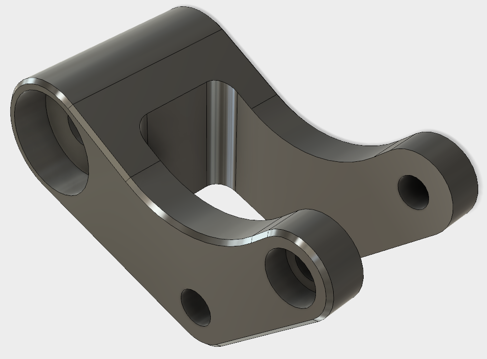
The rocker arm requires three setups to machine using 2.5 axis machining techniques. We will create setup 1 and two of the toolpaths for the setup. Then we will open a finished version to review all three setups.
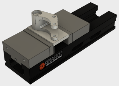
Setup 1
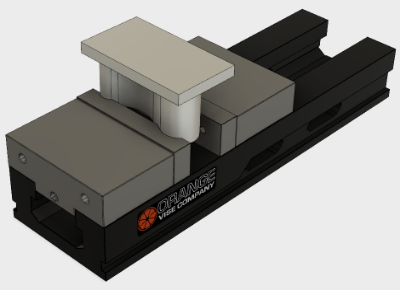
Setup 2
Setup 3
Upload Fusion Data
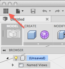
You will use the data panel to upload a Fusion design and CAM toolpaths. Click Open Data Panel to display the data panel.
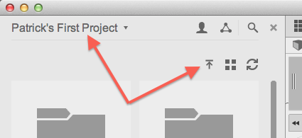
Fusion uses projects to organize designs and related data. Select the desired project from the drop-down, then click Upload to select the files.
Click Select Files, then browse to the location where you downloaded the files attached to this post. Select rocker arm.f3d and rocker arm FINAL.cam360, then click Open. Click Upload to begin the upload process. The files are uploaded to your A360 hub.
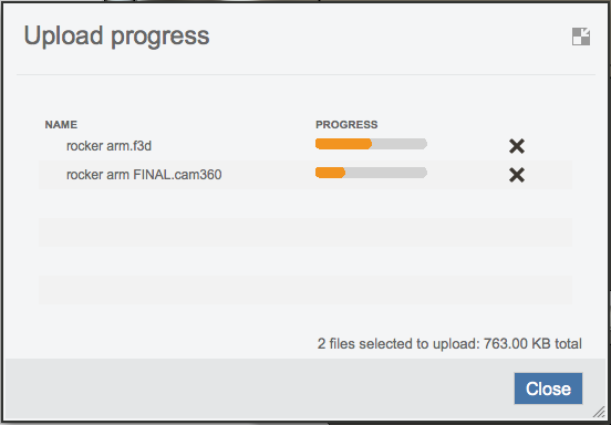
A dialog is displayed to show the progress of the upload and translation process. You can close this dialog and continue working in Fusion while the file processes.
Go to the Fusion CAM Workspace
When the upload is complete, the files are listed in the data panel. Close the Upload progress dialog.
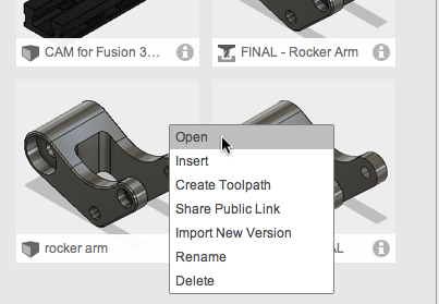
Right-click on the thumbnail and select Open to open the uploaded design.
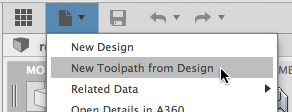
The rocker arm Fusion design is opened. We want to create toolpaths on this 3D design. Click File > New Toolpath from Design.
Create a Setup
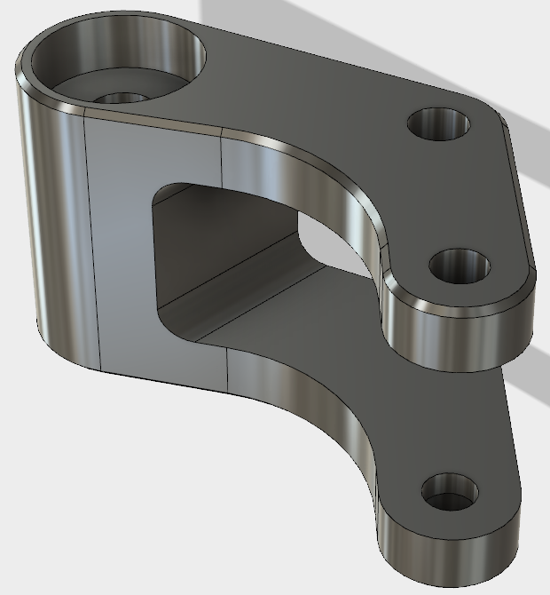
You are taken to the CAM workspace with the rocker arm design loaded. The first step is to create a setup then define the stock size and orientation: Orient, the model as shown.
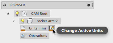
In the Browser, click Change Active units and select Inch.
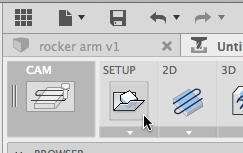
Click Setup to define the stock size and orientation.
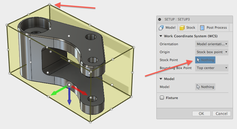
Click Stock Point, then select the upper right stock point to move the triad.
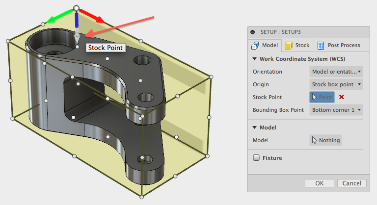
Click the HEAD of the blue arrow to flip it up. Verify that the blue arrow (Z-axis) is pointing up, the green arrow (Y-axis) is pointing to the right, and the red arrow (X-axis) is pointing towards you.
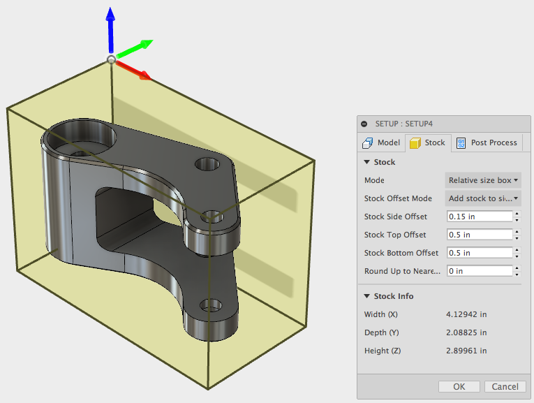
Click the Stock tab to define the stock size.
- Change Mode to Relative size box.
- Stock Side Offset: 0.15 in
- Stock Top Offset: 0.5 in
- Stock Bottom Offset: 0.5 in
Click OK to finish the setup.
Create a Face Operation
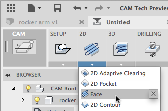
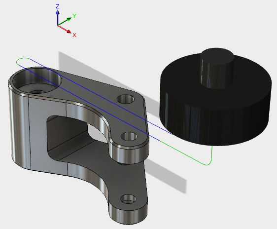
Now we will define two toolpaths to show how this works in Fusion. Start by clicking the Face command.
Click Select next to Tool to pick the tool to use.
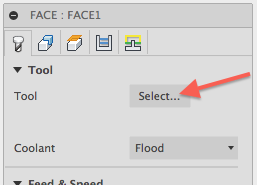
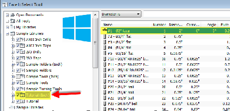
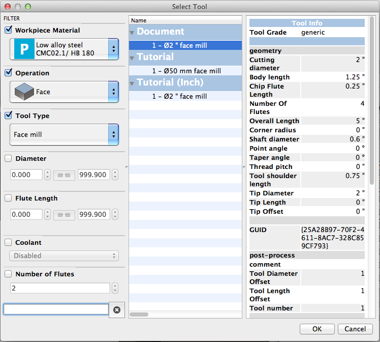
Currently, the Windows and Mac interfaces for the tool library are different. Both libraries are shown below. Select the 2” Face Mill.
Windows:
Mac:
Click OK to finish the toolpath definition.
Create a Clearing Operation
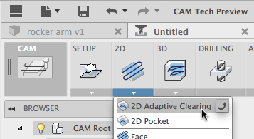
Click 2D Adaptive Clearing to begin defining the second CAM toolpath.
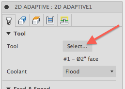
Click Select next to Tool to pick the tool to use.
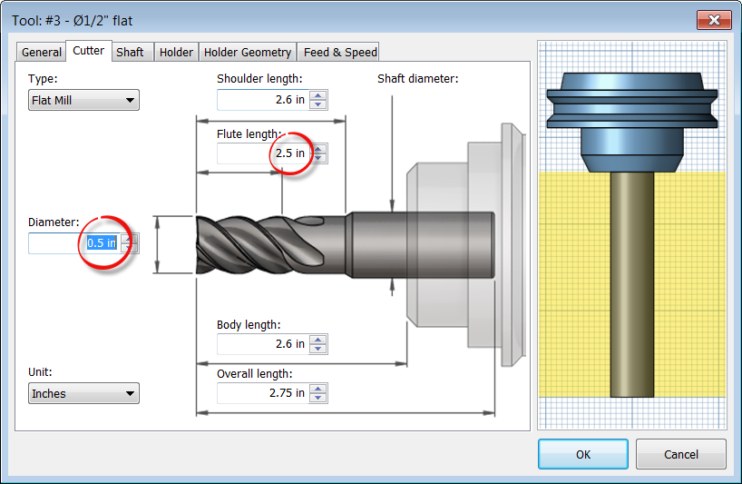
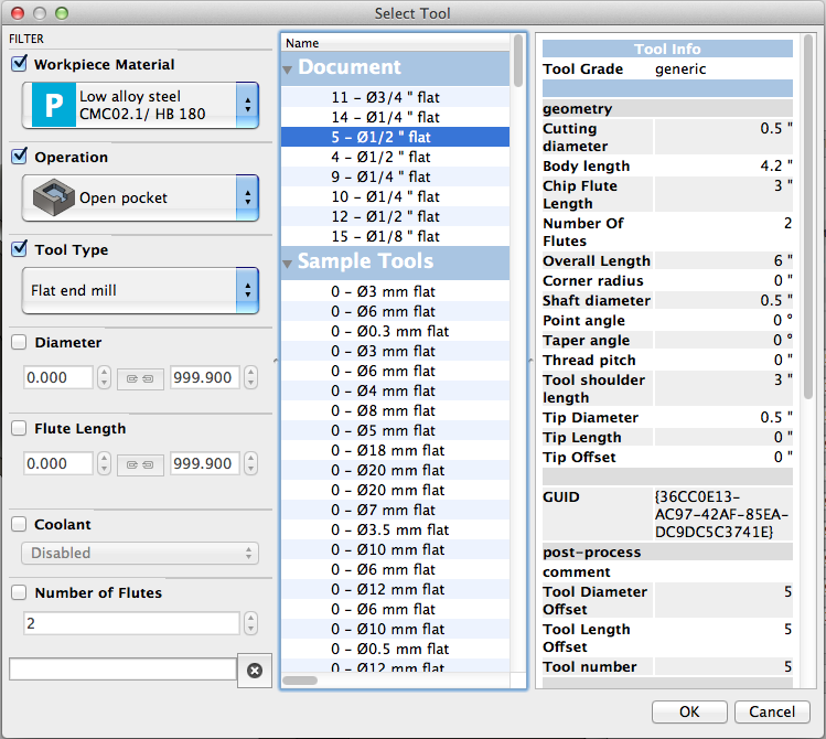
Select a Flat End Mill with a 0.5 in diameter and a Flute Length greater than 2 in.
Windows
Mac
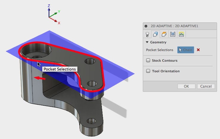
Click the Geometry tab, then select Pocket Selection. Click the top outside edge of the part.
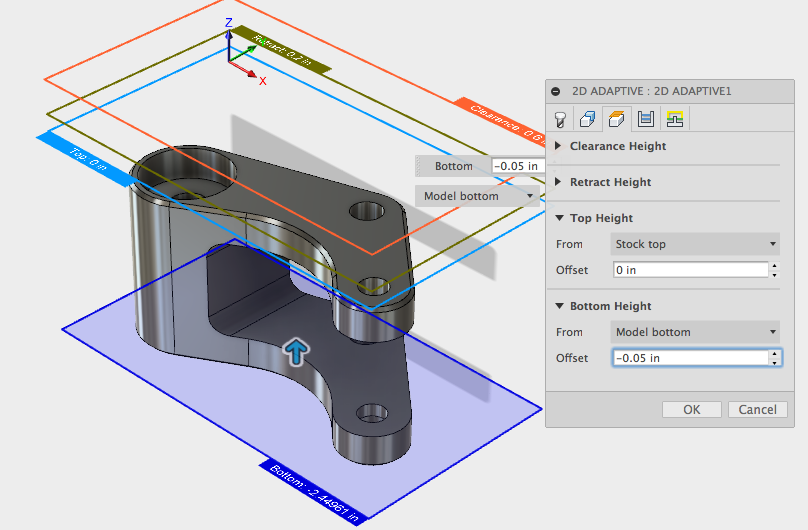
Click the Heights tab. Set the Bottom Height to Model bottom, then set the Offset to -0.05 in.
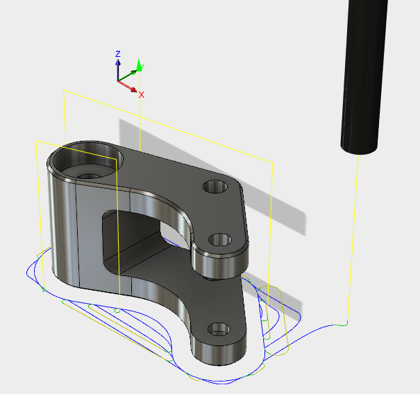
Click OK to complete the operation.
Simulate CAM Toolpaths
Now we will review the completed toolpaths, simulate the operations, and post the NC code. In the Data Panel, right-click on rocker arm FINAL and select Open. This loads the rocker arm with the three completed setups.
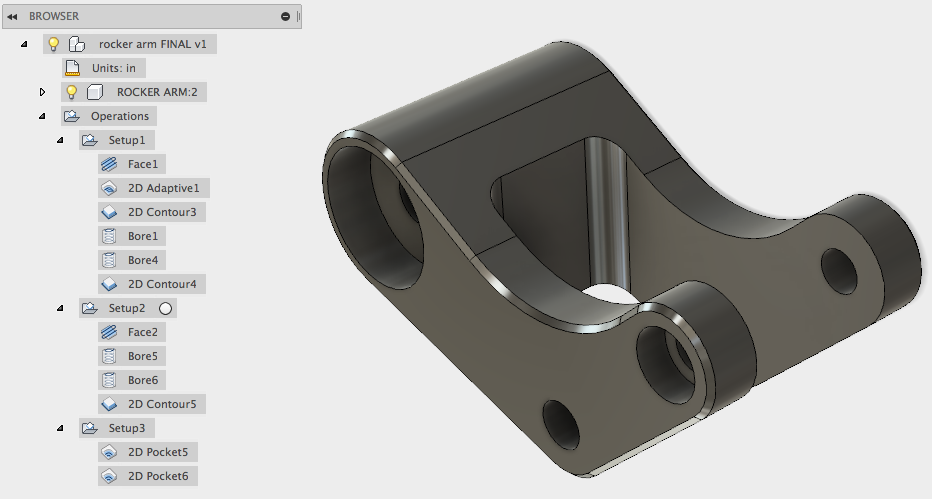
Orient, the model as shown and select Setup 1 in the Browser.
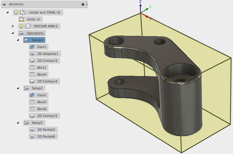
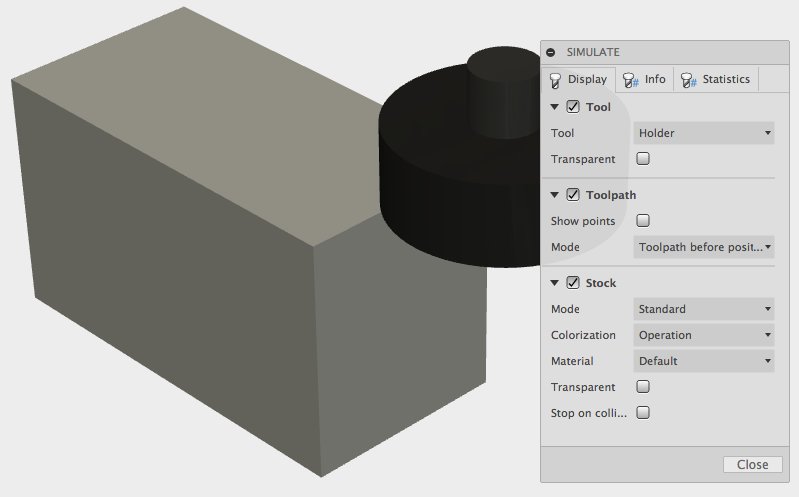
Click Simulate.

Enable Stock in the Simulate dialog box, then click the Start the Simulation button at the application’s bottom. The operations in Setup 1 are simulated. You can step forward and back or change the speed of the simulation. Close the dialog box when done.
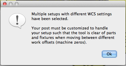
Select all three setups, then click Post Process.

Click OK to the warning about multiple WCS.
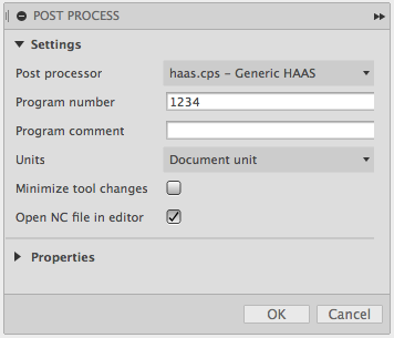
In the Post Process dialog box:
- Set Post Configuration to haas.cps – Generic HAAS.
- Set Program name or number to 1234.
- Click OK
Enter 1234 in the Save As field and click Save to name the file.
Review the code in the NC Editor, then click Close.
You’re done! In this post, we have:
- Created a setup.
- Created two toolpaths for that setup.
- Simulated the completed setups.
- Generated the NC code for the toolpaths.
This should get you started with what’s possible using the Fusion CAM workspace.
