New to Autodesk EAGLE?
The Top 10 Things You Need to Know When Getting Started
We were all beginners at one point in time, and there’s always that overwhelming and exciting feeling you get when using new software. Your PCB design software is no exception. There’s a ton of features inside to explore, and an entirely new world to learn about if this is your first experience with electronics design. It doesn’t make it any easier that each PCB design tool is widely differently with their own unique set of quirks and way of doing things.
So whether this is your first time using PCB design software, or you’re switching over from another tool, here’s 10 things to know about Autodesk EAGLE to make your learning journey an enjoyable one. Think of this as a new user cheat sheet. Print it, save it, remember it!
#1 – Always Keep Your Schematic and Board Editor Open Together
If you’re coming from another ECAD tool, then you might be used to working on just a schematic or PCB layout at one time. And to transfer your changes from one design stage to the next, you might have had to run an Engineering Change Order (ECO), or even export/import your design files between multiple tools.
Autodesk EAGLE takes a different approach to this problem. Rather than disconnecting your design process between a schematic and board layout, everything is seamlessly connected. So if you make a change in your schematic editor, this change will also be automatically reflected in your PCB editor without you having to do anything.
This is a great feature that always keeps your design in sync across all stages of your workflow without hassling you with any intermediary busywork. Here’s the problem, though – if you close either your schematic editor or PCB editor then you’ll lose this real-time connection, and your changes won’t be synced. So whenever you’re working on a project, always keep both your schematic and board editor open at all times to maintain that open connection, otherwise you’ll get to enjoy this lovely error message:
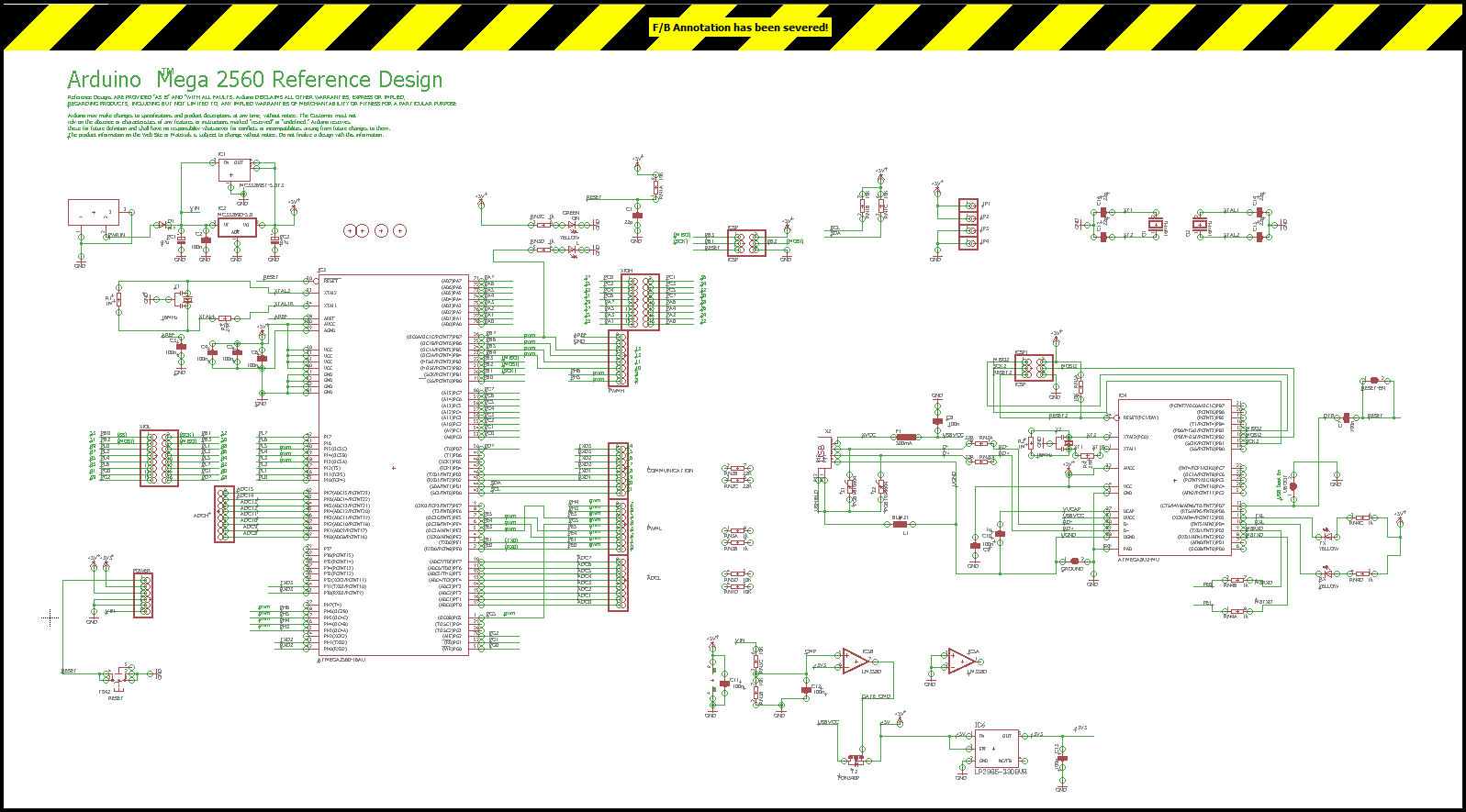
Our changes are no longer being synced between schematic and PCB layout. Watch out for the F/B annotation severed message.
#2 – Stick with the Standard Schematic Grid Settings
By default when working on a schematic, you’ll be set up with a 0.1” (2.54mm) snap grid. This is fixed for a reason – all of the free libraries that ship with Autodesk EAGLE were made with this grid setting. So if you try to place parts or wire together connections with a different grid setting, then you’ll have a heck of a time getting your parts properly connected and aligned.
When in doubt, always leave your grid settings as is for your schematic design. This same guideline doesn’t apply to your PCB layout, though, and you’ll likely need to change your grid settings depending on the density and complexity of your board layout to make your routing job easier.
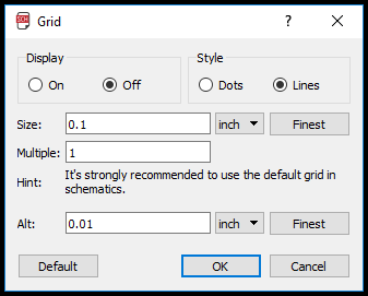
The default grid settings you want to use when working on a schematic.
#3 – Only Use the Line Tool for Artistic Features
Many new EAGLE users in the past have used the Line ![]() tool (previously the Wire tool) to connect nets on a schematic or PCB only to find out that none of their connections were actually made. Woops. They used the wrong tool. Here’s how it works – you only need to use the Line tool for creating artistic features like symbols, notes, or title blocks.
tool (previously the Wire tool) to connect nets on a schematic or PCB only to find out that none of their connections were actually made. Woops. They used the wrong tool. Here’s how it works – you only need to use the Line tool for creating artistic features like symbols, notes, or title blocks.
Outside of that, if you need to connect parts together on a schematic, then you’ll always want to use the Net ![]() tool. And for your PCB layout, you’ll always want to use the Route tool to create net connections between all of your components.
tool. And for your PCB layout, you’ll always want to use the Route tool to create net connections between all of your components.
#4 – Search Precisely or Use Your Wildcard
We might all be a bit spoiled with Google these days. You can jumble your search entirely and still get a reasonably accurate set of results back. But Autodesk EAGLE isn’t as forgiving with your misspelled search terms. If you misspell your search by even one letter, then the part you’re looking for will never show up in your results.
The solution?
If there’s a situation where you don’t know the exact name of the part you’re looking for, then use the wildcard character (*) and the part of the name you do know. For example, using the search term *555 will show any results that have a 555 in its name, which would get us to the LM555 timer that we’re looking. Outside of that, you’ll always need to search for an exact part name to get the results you’re looking for, so double check that spelling!
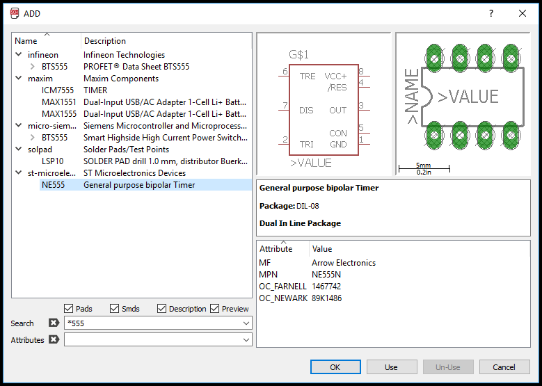
Don’t know the full name? Use the wildcard (*) symbol.
#5 – Choose Your Actions First, Then Your Object
When I first started using EAGLE, I was clicking all over the place, wondering why I wasn’t able to select any of the objects on my design. Beginners mistake there. Autodesk EAGLE does things a little different from other applications. If you want to perform an action on an object, then you need first to select the action you want to perform in your toolbar, and then select the object to apply this action to.
For example, if you want to delete an object on your PCB layout, you first need to select the Delete ![]() tool, then choose the object you want to delete. This can take a bit of getting used to, and in future updates, we’re planning to have it work where you can select an object first and then an action, or vice versa. Until that time arrives, get used to this action-object workflow!
tool, then choose the object you want to delete. This can take a bit of getting used to, and in future updates, we’re planning to have it work where you can select an object first and then an action, or vice versa. Until that time arrives, get used to this action-object workflow!
#6 – Know Where You’re Saving Your Work
You might be tempted to save all of your work in Autodesk EAGLE’s default installation directory, but what happens if you uninstall EAGLE? All of those years of work building libraries and designs have suddenly vanished before your eyes, and that’s no fun.
Rather than saving your work in the installation directly, Autodesk EAGLE creates a default eagle folder in your Documents folder (you’ll find this in your Home directory on Mac or Linux). This folder is where you’ll want to store all of your carefully crafted designs and part libraries. So if you ever need to uninstall EAGLE for any reason in the future, all of these files will still be intact.
#7 – Always End Your Connections at the Exact End of a Pin
If you want to ensure that the pins on your schematic are always connected, then you’ll need to connect them exactly at the end of a pin. Not before, or just a little past, right at the end. How will you know if a net is properly connected to a pin? Try moving a symbol around on your schematic to see if the connected nets follow it around. If they do, then you’re successfully connected!
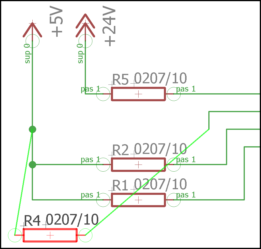
Just move around a schematic symbol to quickly see if its nets are connected.
#8 – Redraw Your Nets Instead of Moving Them
If you find yourself placing down some nets that need to be reconnected to another pin on your schematic, don’t bother using the Move tool to try and move them from one pin to another. This won’t work. Rather, whenever you need to make a new connection or adjust an older one always use the Net tool to redraw the new connection path. And then use your Delete tool to remove that old connection path.
#9 – Don’t Freak Out If You Remove a Part From Your Library Search
There’s a handy button called Un-Use that you can select to remove a part library from the search results in your Add Part dialog. When you select a library and then click this button, it will remove it from your list. But don’t freak out! This doesn’t mean that you have deleted that library forever, you just removed it from your search results temporarily.
This is a great little feature to remove clutter from your search results. But if you find yourself deactivating a library on accident then you can always head on over to your Autodesk EAGLE Control Panel to restore it. To do this, right-click your library in the Libraries folder, and choose Use. You’ll know that your library is back in action if it has a green dot next to it like the rest of your parts libraries.
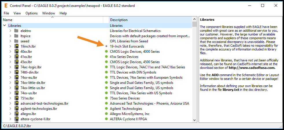
Not sure what library you disabled on accident? Just look for the gray dot in your Control Panel.
#10 – Take Advantage of the Free Parts Libraries
We all know that creating and managing our own parts libraries can be a bit of a chore. And that’s why one of the best things about Autodesk EAGLE is how many free parts libraries it ships with out of the box. What does this mean for you? Way less time spent having to make your own parts as most of them have been created for you! Just grab one from an included library, place it, and you’re done. Here are some of the most useful libraries you’ll want to keep an eye out for:
- rcl – this library will have all of the passive linear components you might ever need, including resistors, capacitors, and inductors.
- Linear – This library will have a ton of common integrated circuits such as the LM741 op amp and 555 timer.
- Supply 1 and Supply 2 – These libraries will have all of the various power symbols you might need for GND and VCC.
- Ref-packages – If you plan to make your own parts then you’ll want to use this library. It contains some of the most common integrated circuit footprints, which you can then copy to your personal library and map to your package. That’s one less step for you in your part creation workflow!
- Frames – This is a handy library that makes documenting your schematic easy with some included drawing frames and title blocks for all common paper sizes.
- Pinhead – You’ll find some of the common 0.1” pitch headers in this library which are used in most electronics projects.
Today a Beginner, Tomorrow a Pro
Autodesk EAGLE is known for its simplicity and accessibility. Features aren’t buried in a bunch of menus that you have to dig through, and everything you need to complete your design is front and center in your interface. Once you understand the unique ways that Autodesk EAGLE works, you’ll be well on your way towards becoming an electronics master!
Do you still have more questions? Sign up for our free First Flights Webinar Series and see Autodesk EAGLE come alive in this live series.