Learn how an optocoupler works to safely separate high-voltage components and low-voltage devices while removing electrical noise.
Need to protect sensitive, low-voltage components and isolate circuits on your PCB? An Optocoupler can do the job. Let there be light!
Elevate your design and manufacturing processes with Autodesk Fusion
What is an Optocoupler?
An Optocoupler allows you to transmit an electrical signal between two isolated circuits with two parts: an LED that emits infrared light and a photosensitive device which detects light from the LED. Both of these parts are contained within a traditional black box with a pair of pins for connectivity. At a glance, it’s easy to mix up an Optocoupler with an integrated circuit (IC).
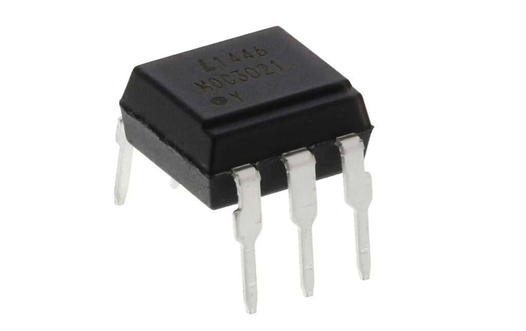
How does an Optocoupler work?
A current is first applied to the Optocoupler, which makes the infrared LED emit a light that’s proportional to the current. When the light hits the photosensitive device, it switches on and starts to conduct a current as any ordinary transistor might.
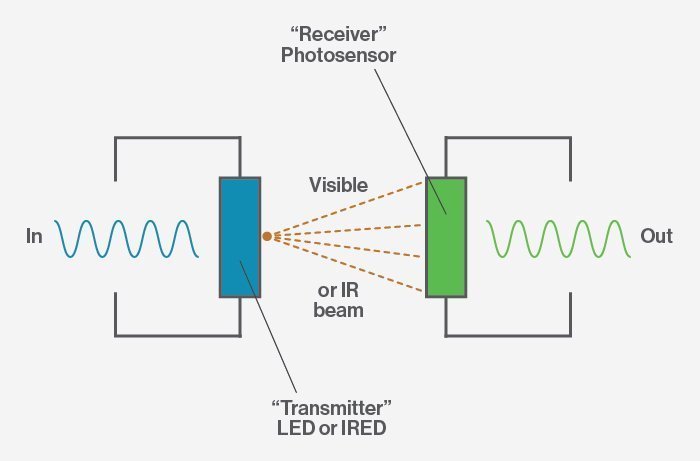
The photosensitive device is typically left unconnected by default to provide the highest sensitivity to infrared light. It can also be connected to ground with an external resistor for a higher degree of control over switching sensitivity.
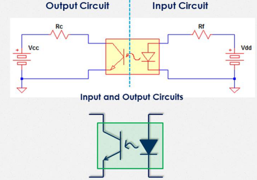
This device basically works like a switch, connecting two isolated circuits on your PCB. When current stops flowing through the LED, the photosensitive device also stops conducting and turns off. All of this switching happens through a void of glass, plastic, or air with no electrical parts between the LED or photosensitive device. It’s all about the light.
Benefits and Types of Optocouplers
If you’re designing an electronic device that will be susceptible to voltage surges, lightning strikes, power supply spikes, etc. then you’ll need a way to protect low-voltage devices. When used correctly, an Optocoupler can effectively:
- Remove electrical noise from signals
- Isolate low-voltage devices from high-voltage circuits
- Allow you to use small digital signals to control larger AC voltages
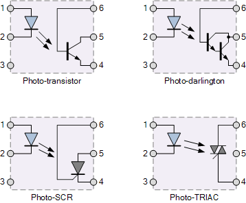
Optocouplers come in four configurations. Each configuration shares the same infrared LED with a different photosensitive device. These include:
- Photo-Transistor and Photo-Darlington, which are typically used in DC circuits
- Photo-SCR and Photo-TRIAC, which are used to control AC circuits
If you’re feeling adventurous, you can even make a homemade Optocoupler with some spare parts. Just combine an LED and phototransistor inside a reflective plastic tube.
Typical Applications
Optocouplers can either be used on their own as a switching device or with other electronic devices to provide isolation between low and high-voltage circuits. You’ll typically find these devices being used for:
- Microprocessor input/output switching
- DC and AC power control
- Communications equipment protection
- Power supply regulation
Within these applications, you’ll encounter various configurations. Some examples include:
Opto Transistor DC Switch
This configuration will detect DC signals and allow you to control AC-powered equipment. The MOC3020 is perfect for controlling a mains connection or providing a gate pulse to another Photo-Triac with a current-limiting resistor.

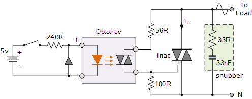
Triac Optocoupler
This configuration will allow you to control AC-powered loads such as motors and lamps. It can also conduct both halves of an AC cycle with zero-crossing detection. This allows a load to receive full power without any significant spikes in current when switching inductive loads.
PCB Layout Guidelines
Before adding an Optocoupler to your PCB layout, consider these three guidelines:
1. Keep Optocoupler ground connections separate
A standard Optocoupler includes two ground pins, one for the LED and another for the photosensitive device. Connecting these grounds will open your sensitive circuitry to any noise from the external ground. To avoid this, always create two connection points, one for external ground pins and the other for input ground wires.
2. Choose the right current limiting resistor value
Selecting a current limiting resistor that operates at an Optocoupler’s minimum value will produce erratic behavior. It’s also possible to choose a resistor that provides too much current, which will pop the LED. When selecting a value for your resistor, be sure to find the value of the minimum forward current from the Current Transfer Ratio chart in your Optocoupler’s datasheet. Vishay has an excellent guide on how to read an Optocoupler datasheet, available here.
3. Know what kind of Optocoupler you need
Not every Optocoupler is created equal, and you’ll need to select the right type for your application. For example, an Opto-Triac is used if you need to control an AC load. Opto-Darlington’s are only for small input currents. If all you need is a standard input isolation, then a general PC817 Optocoupler will get the job done. This article from Nuts and Volts is worth a read to understand Optocoupler types and differences.
Optocoupler available in Autodesk Fusion
The Autodesk Fusion libraries include a whole category of Optocouplers for your next project. It certainly beats having to create your own packages and symbols from scratch! Ready to start isolating circuits and protecting low-voltage devices? Try Autodesk Fusion for free today to start using the included Optocoupler libraries.