Ground has produced a lot of misinformation and confusion in the electronics design world. Let’s get to the bottom of this loaded term: What is it, and why is it so important?
Ground is for potatoes and carrots
One of the reasons that grounding can be such a confusing topic is that depending on the context, it can mean subtly different but related things. That’s why some engineers dislike the term and have coined phrases like the headline of this section. To understand grounding, let’s first define return paths. Once we understand return paths, then it will be easy to understand grounding.
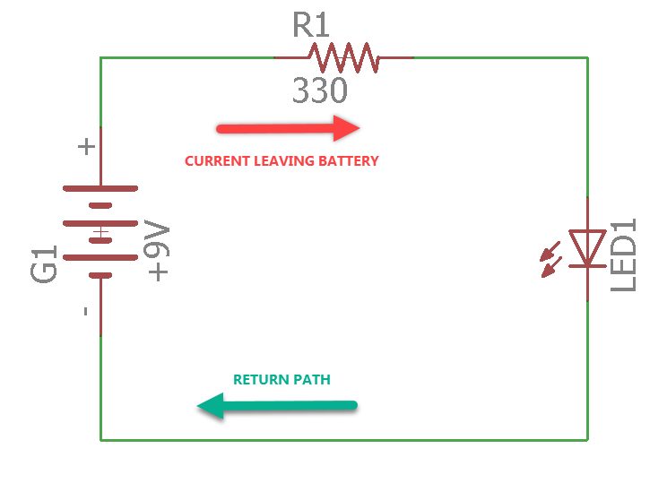
Figure 1, shows a very simple circuit. As you can see, there is current leaving the battery flowing through the resistor, through the LED, and then back to the battery. For any electrical circuit to function, it must be a closed circuit. There must always be a way for the current to return to the source. Regardless of how complex a circuit becomes, there will always be either a trace(s) or a plane that serves as the return path for the current to get back to the source.
In almost all circuits, these return paths are collectively called “ground.” The problem with this is that the term “ground” is also used to define the reference point for the circuit. In most cases, the two coincide (Figure 2), and everything is clear. However, that is not always the case (Figure 3).
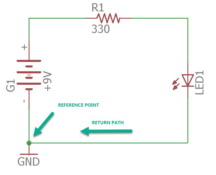
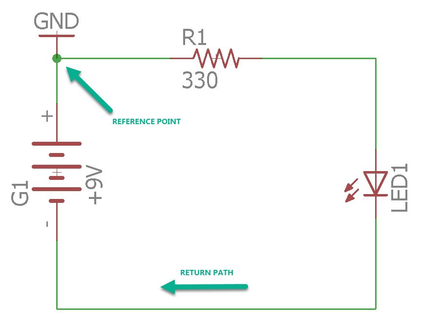
The reference point is necessary because there is no such thing as an absolute zero voltage. When you measure a voltage, it’s always relative to some reference node in your design, and it doesn’t necessarily have to be on the return path. In fact, from a theoretical perspective, any node in your circuit can be the reference node. However, for reasons we will get into later, some nodes are better than others. I’m sure you are starting to see how this can get confusing. The same term refers to two different concepts.
In sophisticated circuits, we can have many return paths. Some of them are sometimes grouped into different grounds. What does that mean? You might be wondering since a few paragraphs ago, I said that all return paths must eventually make it back to the source. This appears to be a contradiction. Look at Figure 4, and we’ll sort this out together.
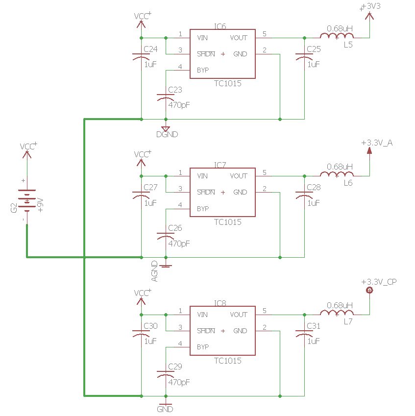
In Figure 4, you can observe at least three different grounds. There’s an analog ground (AGND), a digital ground (DGND), and a general ground (GND).
Notice the three different grounds do return to the source, so this is a valid circuit. However, why separate them if in the end, they are all just going to return to the source anyway? The quick answer is by having the return paths grouped into three grounds so we can isolate noisy currents in one circuit from the others.
For example, the currents running through the AGND circuitry only run through those components connected to AGND. By designing the circuits this way, the currents only interact with each other back at the source. Using our previous definitions, we can see that all the return paths are making it back to the source, it’s just that their arrangement has been carefully designed to provide some noise immunity between the three circuits.
Earth, Chassis, and Signal Grounds
Armed with our new definitions, let’s analyze some commonly used “grounds.” You’ll realize that they all work the same way. Their different names come from the context of their application.
Earth ground
Earth (the soil beneath our feet, not the planet) is considered an infinite source of electrons and defines the reference point for all the electrical wiring in our homes (Figure 5). In practical terms, this return path is “connected” by driving a metal rod into the ground and making sure that all the “ground” wiring in our homes bonds (connects) solidly to it.

CHASSIS GROUND
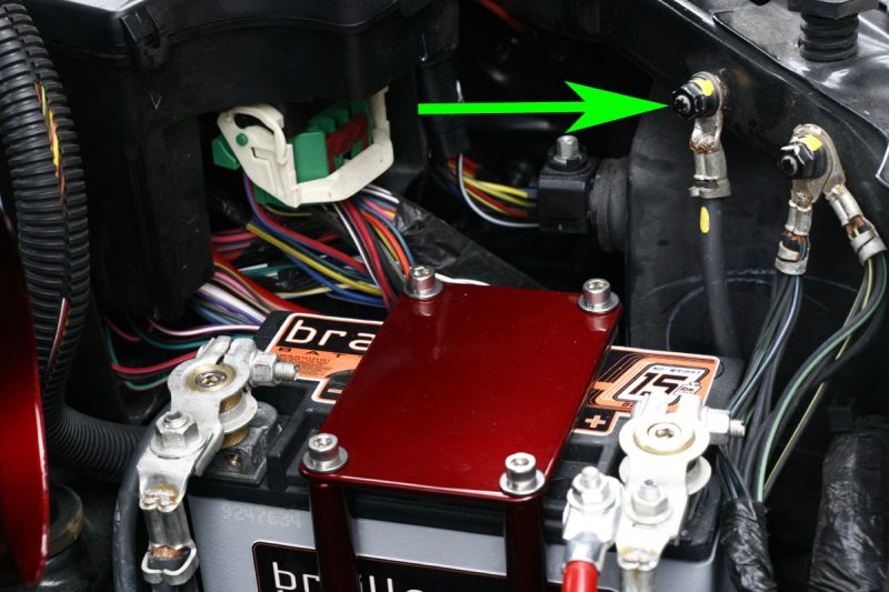
This type of ground gets its name when the metal enclosure of a device is defined as a reference point for an electrical circuit. This is the case of a car (See Figure 6), a washer, or any other device that has an electrically conductive enclosure. The main reason for using the chassis of an enclosure and the earth as reference points has to do with safety. Our bodies are almost always at earth potential (or very nearly so).
Imagine, for a moment that you are going to do your laundry. Inside your washing machine, all the electronics are connected to the chassis (chassis ground), and the chassis is connected to the ground plug of your outlet (earth ground). What happens if the high voltage line inside your washer short to the chassis? Figure 7 has the answer.
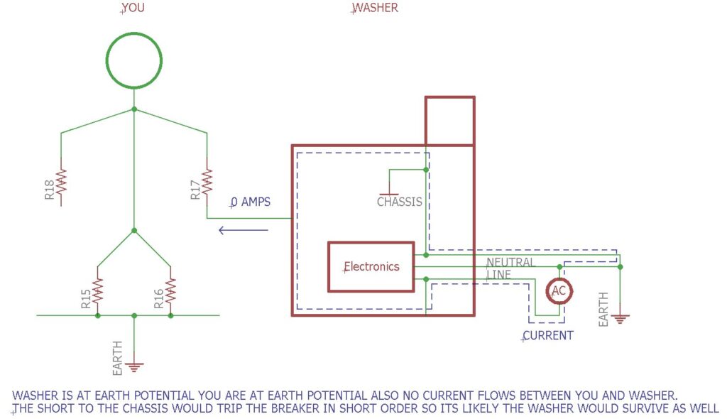
As you can see, if the chassis and earth grounds are used, then the return path is guaranteed to avoid the human body in case of contact with the washer’s enclosure during a fault. Again, if we think in terms of return paths, you’ll see that in this example the chassis ground and earth ground from a return path to the AC source. This avoids a difference in potential between your body and the washer’s enclosure which would cause current to flow through your body.
Let’s repeat the scenario. What happens if for some reason the washer’s chassis is not connected to earth? Figure 8 shows the painful result.
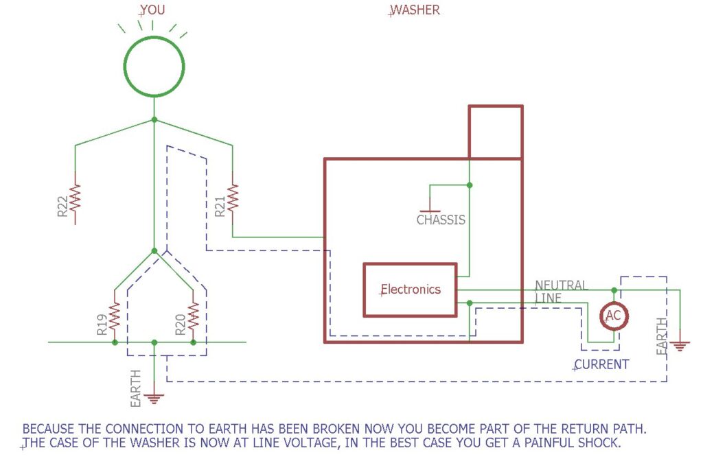
In this scenario, you are not a happy camper. The connection to earth ground has been severed, there is only one viable return path for the AC current, you. In this scenario, the second you make contact with the washer enclosure, you get a shock. What’s worse is that often the current is not enough to trip a breaker, and you could be shocked for a prolonged period of time. Through a wise choice of reference nodes, the return paths are set up in such a way as to keep you safe. As you’ve realized, naming these nodes “ground” muddles the understanding of how these safety measures work.
Signal ground
This is the most common designation. It’s basically a definition of the reference node for the circuits on our PCBs. It’s usually physically implemented using a ground plane. That way there is a low impedance return path to the power source in our design (See Figure 9). This is important. Otherwise, different “grounds” on the board may be at different potentials (the reference node doesn’t have the same value everywhere), which could cause the circuit to malfunction or just not work.

Do you really need ground?
As we have learned, every single electrical system needs at least one return path back to the source. So in that sense, all circuits need a ground. Typically, this ground will also be used as the reference node against which all the voltages in the circuit can be measured. However, not all circuits connect to line voltages (i.e. battery-powered devices), so they won’t all need an earth ground or more correctly a return path through the earth.
Similarly, devices in non-conductive enclosures don’t need a chassis return path for safety. What we need is to be able to call these paths something else to avoid confusion with ground, but that’s an issue beyond the scope of this article.
How to recognize ground in a schematic
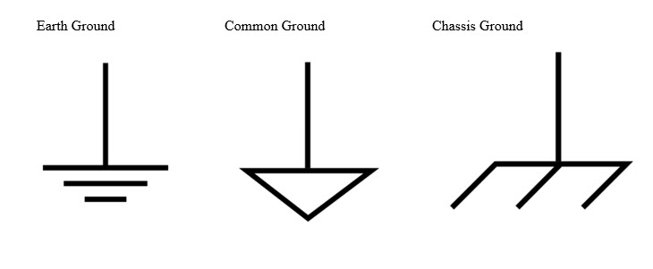
Now that you know what each of these types of grounds are, it’s important to know how to recognize them in a schematic. That way, your electronics can work properly and safely. Below you’ll find the most commonly used symbols to represent signal, chassis, and earth ground. While these are standard symbols, you may run into a schematic that deviates from them. If this happens, please be sure to verify. Doing so will make sure that you are safe.
We hope that this article has helped clear up some of the confusion around what ground is. It’s a loaded term, and depending on the context, it can refer to a return path, a reference node, or both. Keep in mind that this is just the tip of the iceberg. There are entire books about grounds and how to implement the return paths in various applications.
You now have the basis to understand those books and make the proper design decisions in your circuits. By designing your return paths carefully, you can minimize cross-talk between different parts of your circuit and keep users of your products safe, which will help you sleep at night. Have fun designing, and remember: The ground is for potatoes and carrots!