In this article, you’ll learn how to create and modify basic 2D sketch geometry for a sketch profile that you can use to create 3D solid, surface, or T-Spline bodies in Fusion 360. We’ve also included an accompanying video below that you can use to follow along. Please let us know if you find the video helpful by leaving feedback on our Self-Paced Learning site.
If you’re creating a design that will contain multiple components, create and activate the component you want the sketch to appear within as you get started.
Next, in the Design workspace, on the Solid tab, select Create Sketch from the toolbar. Then select the sketch plane to enter the Sketch environment.
The Sketch contextual tab displays on the toolbar. Now, let’s explore the different tools for creating and modifying geometry in the sketch environment.
Create Sketch Geometry

The Create menu contains tools that let you:
- Add basic geometry like lines, rectangles, circles, arcs, polygons, slots, points, and text
- Mirror or pattern basic geometry
- Project reference geometry from outside the sketch onto the sketch plane
Access Tools From the Toolbar Menu
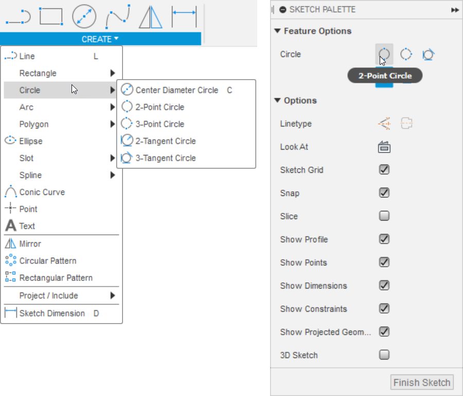
On the toolbar, you can select commands from the menu, like Create > Circle > Center Diameter Circle. Or if you press the shortcut key, C, on your keyboard, the Center Diameter Circle tool starts by default.

In the canvas, click anywhere to place the center point of the circle.
If the Snap and Sketch Grid settings are checked in the Sketch Palette, you can snap to the Sketch Grid to quickly create precise geometry.
Next, move the mouse pointer away from the center point. A preview of the circle moves with it, along with a diameter value input.
If you specify a value for the diameter on the fly, a dimension is added to the geometry automatically. But if you click to place the circle, it remains unconstrained.
Keep in mind that it’s good practice to define sketch geometry relative to the Origin on the sketch plane. You can always add dimensions and constraints later.
Switch Tool Types on the Fly
Some tools, like Circle, let you switch types on the fly instead of returning to the toolbar menu. For example, in the Sketch Palette, if you’d prefer to create a circle by placing two points to define its diameter, you can switch from the Center Point Circle type to the 2-Point Circle type, then place the next circle.
Once you’re finished creating geometry with the current tool, you can press Esc to exit it, or you can start another one and continue sketching.
Access Tools From the Shortcut Menu
You can also use the Shortcut menu to access sketch tools more quickly.
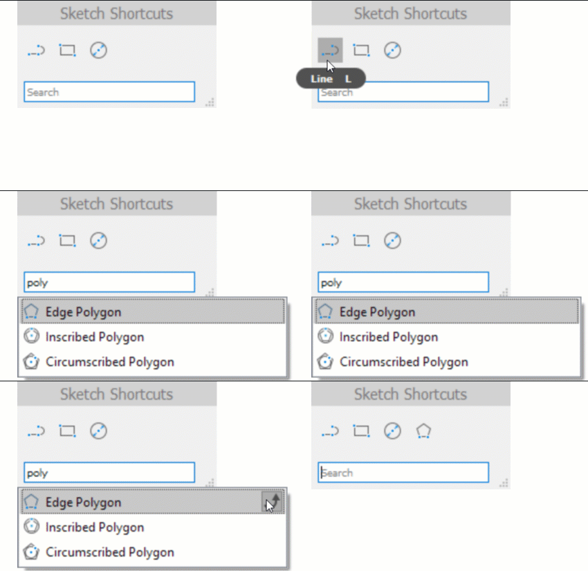
Press the S key to display the Shortcut menu, search for a tool, like Line, and select it. If you use a particular tool frequently and don’t want to search for it each time you use the Shortcut menu, you can click Add To Shortcuts to pin it to the top of the menu.

If you hover over existing sketch geometry, blue Auto Snap Markers display to help you snap to the geometry. If you snap and drag away from certain geometry, dashed blue Tracking Lines appear to help you align geometry as you sketch. If you want to temporarily disable the Auto Snap features, press Ctrl (Windows) or Command (macOS) while you sketch.
With Auto Snap enabled, you can snap to the endpoints of existing geometry and click to add to it until you get the base geometry you are after. Auto Snap helps you avoid creating tiny gaps between objects, which could prevent a sketch profile from closing completely.
As you click to connect points or ends points on lines, Fusion 360 will continue to add to the lines until you tell it otherwise.
You can click and hold an endpoint, then drag away from it to create a curved line segment.
When you’re finished, you can either click the green Checkmark or double-click on an endpoint to break the chain of lines and remain in the Line tool. As with other tools, you can also complete your use of it by pressing Esc or starting another sketch tool.
Construction and Centerline Geometry
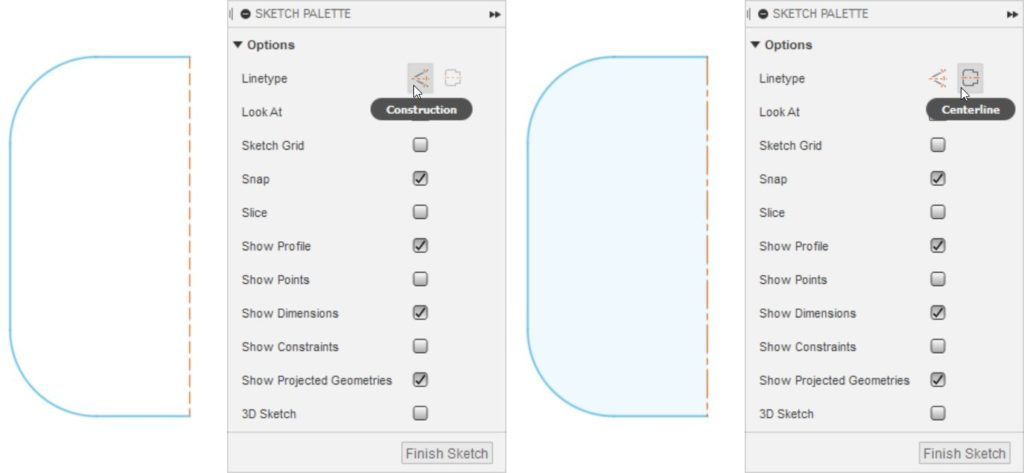
You can select geometry in the canvas at any time. Then in the Sketch Palette or the Marking menu, select the Construction or Centerline icons to switch the line type of the geometry.

Notice that Centerline Geometry still contributes to the sketch profile, acting as a boundary to close it, while Construction Geometry does not. You can identify a closed profile by the blue highlighted area.
If you’re having trouble closing a profile in the Sketch Palette, make sure Show Profile and Show Points are both checked to help identify any small gaps you may need to close, where endpoints are close to each other but not quite touching.
Modify Sketch Geometry

Once you’ve created the general shape of your sketch profile, you can use the tools in the Modify menu to:
- Offset geometry
- Add details like fillets and chamfers
- Adjust existing geometry as you build your sketch profile
Break and Switch Geometry Type
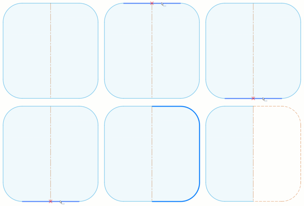
You can use the Modify > Break tool to split geometry into multiple segments so that you can switch some of the segments to Construction Geometry or Centerline Geometry. Hover over the geometry you want to break. Then when the red X’s display at the points you want to break, click and the sketch geometry will split at those points.

Press Esc to exit the tool, then select the segments you want to change to a different geometry type. Hold Shift to select multiple objects at once. In the Sketch Palette, click the Construction or Centerline button, and the selected objects switch to the new geometry type.
Offset Sketch Geometry
Some commands, like Modify > Offset, let you automatically select an entire series of connected segments by using Chain Selection. You can drag the manipulator handle in the canvas to adjust the offset distance. Then, press Enter or click OK in the dialog to complete the offset.
Drag Unconstrained Geometry
While sketch geometry is unconstrained, you can click and drag it in the canvas. This can help you understand where the sketch profile is still free to move and where it is already constrained.
Early in the design process, it may be useful to leave some elements of a sketch unconstrained as you experiment with the overall shape. As your design intent becomes clearer, you can add dimensions and constraints to your evolving sketch profiles until they are fully constrained. A well-defined, fully constrained sketch profile leads to robust, intelligent, and predictable downstream parametric features, especially in complex assemblies.
Now you know how to create and modify basic 2D sketch geometry for a sketch profile that you can use to create 3D solid, surface, or T-Spline bodies in Fusion 360.

