Metal Powder Bed Fusion simulations enable teams to identify errors before production. Learn how to run them in Autodesk Fusion.
As manufacturing standards and component performance requirements rise, the demand for additive manufacturing simulation tools has increased. This is especially true for Metal Powder Bed Fusion (MPBF), which is gaining traction in the aerospace and automotive industries.
Metal Powder Bed Fusion, as referred to in Autodesk Fusion, encapsulates SLM, DMLS, and EBM additive manufacturing technologies.
Given the intricacies of MPBF technology, simulating this manufacturing process in advance becomes crucial to validating engineering work and optimizing processes. Essentially this process enables teams to visually identify design errors before actual production.
This article will explore the MPBF process simulation workflow in Autodesk Fusion. For more information on the general additive manufacturing simulation workflow, please read this recent article.
What is a Metal Powder Bed Fusion process simulation?
Metal Powder Bed Fusion process simulations are the thermo-mechanical analysis of parts manufactured using MPBF. Autodesk Fusion simulates a part’s behavior during the additive manufacturing process using a multi-scale modeling approach. The simulated results show predicted displacement and projected print failures, like interference with the additive machine’s recoater blade.
For a more detailed explanation of the simulation approach, please read this page.
What are the benefits of running Metal Powder Bed Fusion process simulations?
The main benefit of simulating the additive manufacturing process is to minimize defects and failures where the issues within the build may arise. This allows the user to compensate through redesign or via automatic compensation, therefore improving predictability and reliability, decreasing time, and increasing resource and cost savings.
How do I run a Metal Powder Bed Fusion process simulation in Autodesk Fusion?
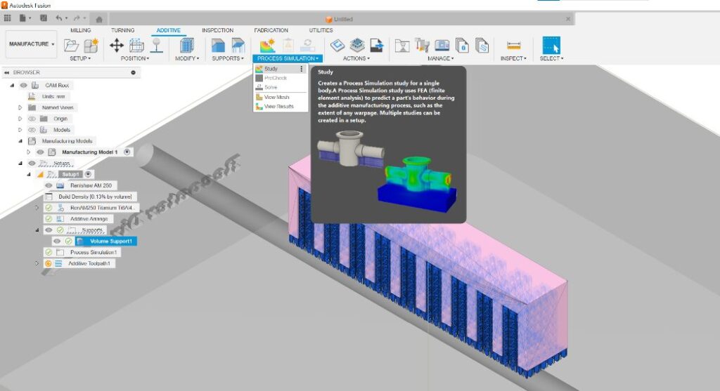
MPBF workflows, including process simulation, can be accessed in Fusion via the Autodesk Fusion Manufacturing Extension. This extension enables support structure and toolpath creation and simulation of the MPBF Fusion process.
There are three main stages to an additive manufacturing process simulation:
1. Generating a mesh
The preliminary step of simulating the Metal Powder Bed Fusion process in Fusion is to create a setup with an MPBF machine in Fusion to ensure that the model is correctly oriented and supported.
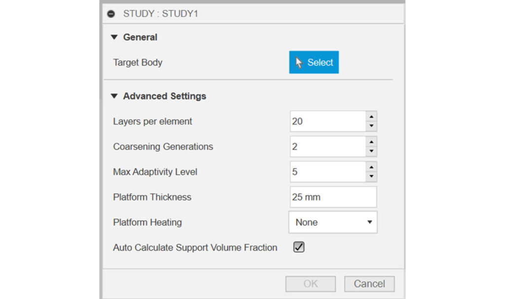
From this, the first step is to generate a mesh of the setup. This is crucial since a voxel representation of your model is required in to fully simulate the process and its effects.
For an in-depth explanation of the mesh settings, please read our Autodesk Netfabb Local Simulation Mesh Settings help page.


2. Solving
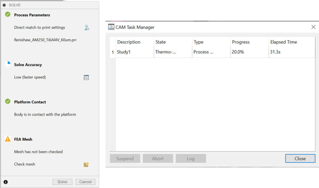
The second step is to initiate the solver by clicking “solve” on the next dialog box. Progress can be tracked using the CAM task manager.

3. Analyzing the simulated results

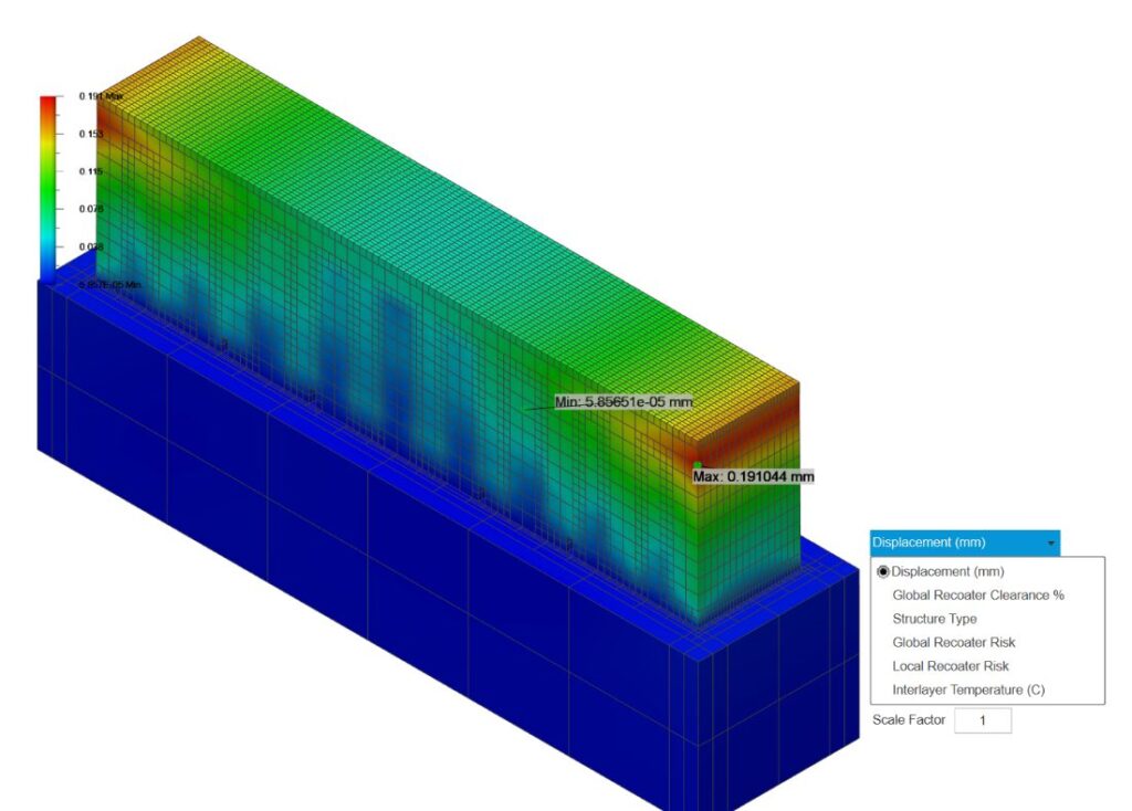
The third step is to analyze the simulated results. Once the solving is complete, you will be presented with a visual representation of the displacement of certain areas of the model. This can be changed to other useful visual options such as:
- Displacement (mm)
- Global Recoater Clearance %
- Structure Type
- Global Recoater Risk
- Local Recoater Risk
- Interlayer Temperature (°C)

Finally, you can either run the build if the results look good or, export a compensated STL of the build. A compensated STL will pre-distort the geometry, meaning that the final part distorts into the correct shape.