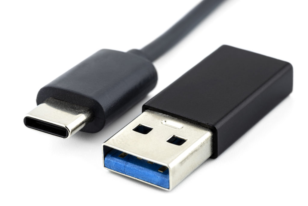
USB ports are one of the most popular connectors around the globe. Nowadays, almost every electronic gadget and device that utilizes wired connectivity uses USB connectors. It has become a standard interface for computers and other consumer electronic devices. But what is USB, and how do you integrate one in your next PCB design? Let’s find out.
What is USB?
USB stands for Universal Serial Bus, an industrial standard that specifies the connection protocol and power limits while communicating between two or more devices. The technology allows us to connect many devices such as smartphones, computers, cameras, and printers to one another. This is why we can use the same USB keyboard with our PC or smartphone seamlessly.
USB Types and Specifications

Depending on the application, there are quite a few USB types available. And sometimes, distinguishing between them is confusing. For the sake of simplicity, we will cover only the most commonly used USB types.
There are three types of USB which are
- Type A
- Type B
- Type C
They are further categorized as Standard, Mini, and Micro, depending on the port’s physical shape. Among which Standard Type A connectors are the ones that you can find on most of the devices. Standard Type-B connectors are used in some old printers and cameras. Micro USB Type B is mostly used in mobile devices and small accessories due to its small size. USB Type C is relatively new, and it offers some impressive specifications in terms of data transfer speed and high power handling capability. It is designed to replace both A and B types with smaller ports to support mobile devices’ small form factors better. That’s why it is getting more and more popular these days.
Then there is another USB classification based on generations:
- USB 1.x
- USB 2.0
- USB 3.0
- USB 3.1
The first generation USB types are mostly outdated due to the vast improvement in the second generation. Hi-Speed USB 2.0 can transfer data at the rate of up to 480 megabits per second (Mbps), or 60 megabytes per second (MBps). The current-carrying capability also increased to 2A, which enables to charge a device even faster. The latest version of the USB protocol, USB 3.0 and 3.1, can transfer up to 10 Gbps rates. Simultaneously, its intelligent power delivery (PD) system allows you to deliver up to 100 watts of power without an issue, hence it becomes a genuinely universal connectivity standard for modern devices. That’s why most of the latest devices use USB 3.0 and 3.1 for improved performance and speed.
Each USB version is both backward and forward compatible, meaning you could plug a USB 3.1 connector on the USB 2.0 port or vice versa. But the data transfer speed and power handling capability will be limited to the lower version port.
Pin Configurations
A Standard USB type A or Type B typically has four pins:
- VCC
- DATA+
- DATA-
- GND
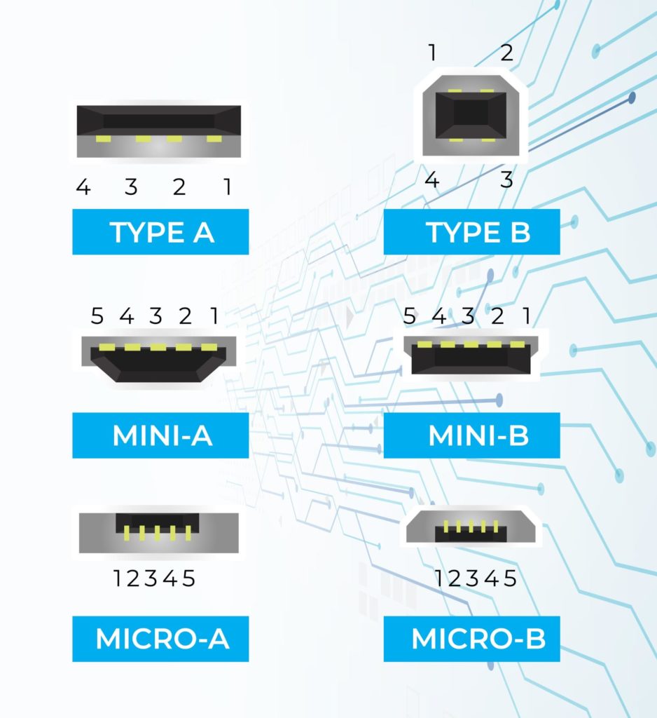
On some USB ports, you may have the 5th pin. This is mainly seen on the micro and mini USB ports and is labeled as an ID pin. This pin is for On-The-Go(OTG) to select which device is the host or slave. The micro-A plug has the ID pin grounded, while the ID in the micro-B plug is floating. The device that has a micro-A plugged in becomes an OTG A-device, and the one that has micro-B plugged becomes a B-device.
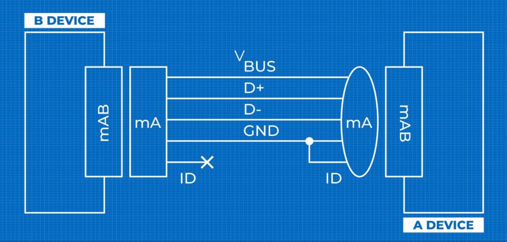
As compared to other 4-pins USB devices, where there is no ID pin, the advantage is to distinguish the host device from slave devices.
- Host: ID connected to GND
- Slave: ID not connected (floating)
Keep this in mind while designing an OTG enabled device. Without the ID pin, the system might not detect which one is the host and which one is a slave device.
USB Type-C
While previous USB types had 4 or 5 pins, USB type C has surprisingly 24 pins. And it has to be as it offers tons of new features. Unlike its USB predecessors, the Type C port pins are also flipped, so you don’t need to try three times to plug it in.
USB Type-C Features
The USB-C interface has three main features to offer:
- It is designed in such a way that the plug can be flipped relative to the receptacle.
- It allows the devices to negotiate and choose an appropriate power level through the intelligence power Delivery system.
- It supports USB 2.0, USB 3.0 and USB 3.1 Gen 2 standards. Moreover, it can support third-party protocols such as DisplayPort and HDMI in a mode of operation called Alternate Mode. This allows a wider range of devices that use the same Type-C interface for communication.
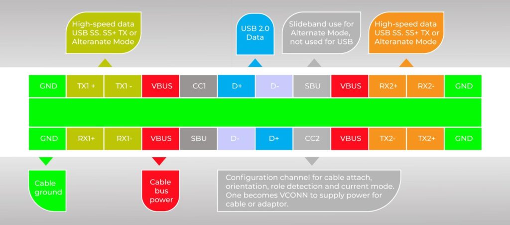
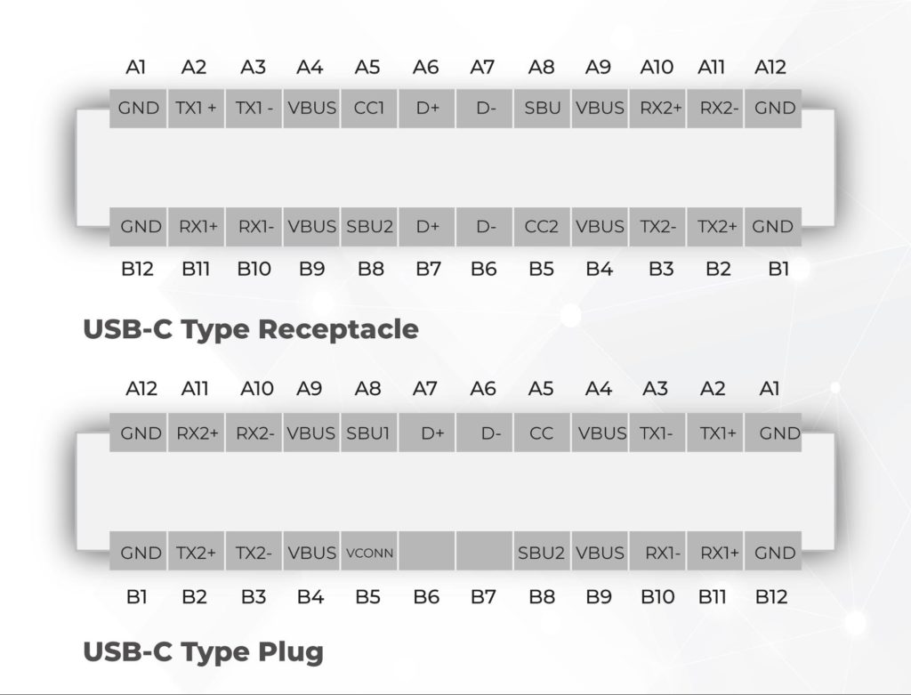
As you can see from the above pin diagram, 12 pins are mirrored on the other side. This gives it the ability to insert both ways.
USB 2.0 Compatibility
The D+ and D- pins are used for the USB 2.0 connectivity. There are two differential pairs in the receptacle. However, on the plug side, there is only one set of pins used. The redundancy is included only to provide a flippable connector.
Power Pins
The default VBUS voltage is 5V, but the standard allows the devices to negotiate and choose a different VBUS voltage other than the default value. It could be 9V, 12V, etc. The power delivery also allows the VBUS voltage to have up to 20V, while the maximum power consumption could get up to 5A. Thus, the USB Type-C’s maximum power delivery capability is 100W, which is significantly higher than most consumer electronics devices. So if your device has more power requirements, then USB type-C is the way to go.
USB Type-C PCB layout
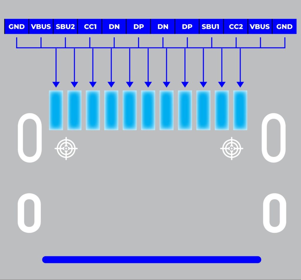
Full Pin reference is given below:
| Pin | Name | Direction | Color | Description |
| A1 | GND | white | Ground | |
| A2 | SSTXp1+ | —> | blue | SuperSpeed transmitter (pair 1) |
| A3 | SSTXp1- | —> | yellow | SuperSpeed transmitter (pair 1) |
| A4 | VBUS | red | Bus power (+5V) | |
| A5 | CC1 | black | Configuration channel 1 | |
| A6 | D+ | <—> | green | USB 2.0 data |
| A7 | D- | <—> | white | USB 2.0 data |
| A8 | SBUS1 | Sideband use (SBU) | ||
| A9 | VBUS | red | Bus power (+5V) | |
| A10 | SSRXp1+ | <— | purple | SuperSpeed receiver (pair 1) |
| A11 | SSRXp1+ | <— | orange | SuperSpeed receiver (pair 1) |
| A12 | GND | white | Ground | |
| B1 | GND | white | Ground | |
| B2 | SSRXp2+ | <— | purple | SuperSpeed receiver (pair 2) |
| B3 | SSRXp2- | <— | orange | SuperSpeed receiver (pair 2) |
| B4 | VBUS | red | Bus power (+5V) | |
| B5 | CC2 | black | Configuration channel 2 | |
| B6 | D+ | <—> | green | USB 2.0 data |
| B7 | D- | <—> | white | USB 2.0 data |
| B8 | SBUS2 | Sideband use (SBU) | ||
| B9 | VBUS | red | Bus power (+5V) | |
| B10 | SSTXp1- | —> | blue | SuperSpeed transmitter (pair 2) |
| B11 | SSTXp1+ | —> | yellow | SuperSpeed transmitter (pair 2) |
| B12 | GND | white | Ground |
USB Drivers
Since there are so many USB enabled devices, we often need so-called USB driver software to communicate with the peripheral device. Sometimes it’s already preinstalled in our PC or laptops, such as for USB keyboard or mouse, and we can continue to use it straight away. Other times we need to install the specific driver to use that device. Such as for printers etc. The driver is basically a chip inside the device that lets us talk to the device. It acts as a medium between the two.
Examples of such driver IC can be CP2102 or CH340. These are highly integrated USB-to-UART Bridge Controllers that provide a straightforward solution for updating RS-232 designs via USB using fewer components and PCB space. They are widely used to communicate with microcontrollers, updating firmware and debugging over serial COM ports.
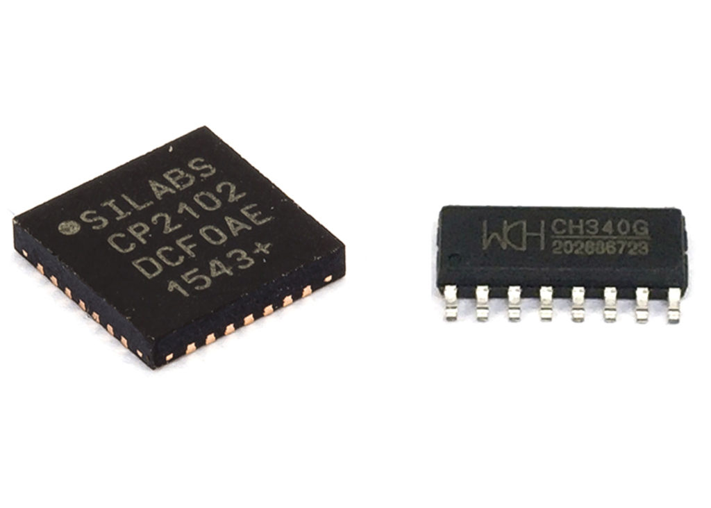
For using this drivers you will also need the driver softwares which you can get from their official sites
While designing your own circuit or PCB that uses USB connectors, you need ensure the following things
- Size and Footprint compatibility: Depending on the manufacturers, it’s often seen that the physical appearance of the USB connectors are not always the same. And this could be a serious problem. Because if the connector isn’t compatible with the PCB footprint, it won’t fit perfectly in the PCB, so always verify the footprint with the actual product.

- USB Driver: Choose appropriate drivers carefully based on your requirement. Make sure the driver is compatible with the rest of the hardwire. The voltage level is also an important factor. Some circuits work on 5v logic while some on 3.3v. You may need to lower the voltage down if required. Always check the datasheet for more information and reference circuits and pin diagrams.
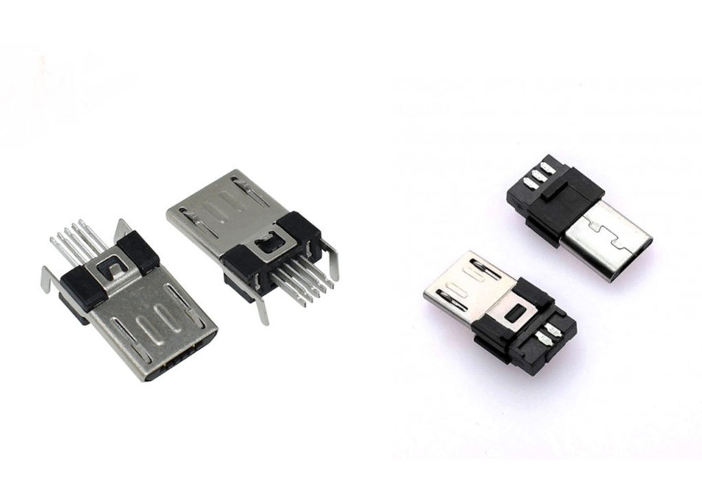
- Using Appropriate connector types is also very important. For example, if you are designing a battery charger module and giving the input from a USB outlet, you should use a micro USB female connector because that’s the type of cable you usually get. Similarly, if it’s a pluggable device, then the connector type will be Standard male type-A. Or Male micro USB for OTG devices. It is also noted that some connectors of similar types are PCB mountable (fig.1) while others are for connecting directly to the cable (fig.2).
USB to Serial Converter
Here is a simple circuit schematic of a typical USB to Serial converter:
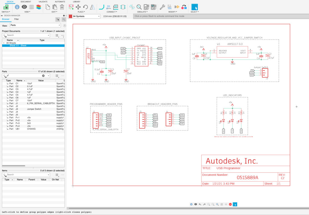
This is the circuit diagram for a USB ISP programmer module. It is used to communicate with devices that don’t support USB out of the box. It works bi-directionally, meaning we can use it to send commands to the target device or receive the output in a human-readable format. The heart of the circuit is the CH340 chip, which makes communication possible. So let’s see how it works.

What is a CH340 Chip?
CH340 is a USB bus driver IC that can connect USB and serial UART (Universal Asynchronous Receiver/Transmitter) interfaces. You may have seen such driver ICs in boards like Arduino, NodeMCU, and some other microcontrollers. Because generally, these microcontrollers don’t have support for the full-speed USB device interface built-in. So, we need a driver that can act as a medium to talk to these devices. This IC does just that. It takes input commands from the USB device, essentially a laptop or a computer, and translates it to the TTL (transistor-transistor logic) levels, often 0 bit = 0V and 1 bit = 5V / 3.3v. And the target device uses these TTL voltage levels for serial communication.

CH340C Chip Variants
There are a few variants of the CH340 chip. Out of which, the most popular ones are CH340G and CH340C. The CH340G requires an external crystal oscillator to function, while the CH340C includes a built-in crystal oscillator. However, both function in the same fashion – they convert USB data for a serial UART and vice versa.

Driver Software
To use this IC, you need to have the appropriate driver installed in the host device. In some devices, this might be preinstalled. But if you haven’t, you can download it from the manufacturer’s website or here. If you are unsure whether the driver is installed or not, you can check it by simply going to the device manager after connecting the device.

If you see the device is detected under COM ports like this, that means the driver is installed successfully. And you can also note down the COM port number assigned to it (COM6 in this case) for future reference.
How it Works — Example
For this example, we are using the USB to serial converter to upload a program to the Arduino pro mini dev board.
Step 1: Set Logic Level
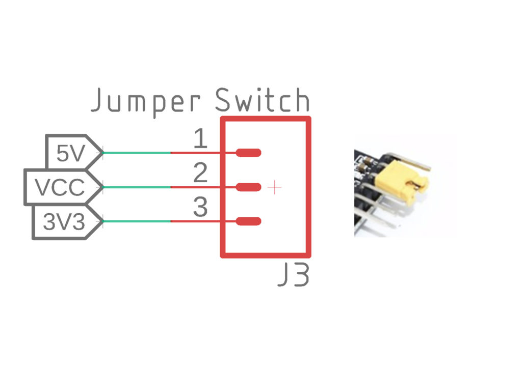
This serial converter can work on both 5v and 3.3v logic levels. So, depending on the application, you might have to change that. For example, ESP8266, ESP32 chips work only on a 3.3v voltage level, and anything higher than that value might destroy the IC, so you have to set the voltage level to 3.3v. To do that, you have to toggle the given jumper to a 3.3v pin.
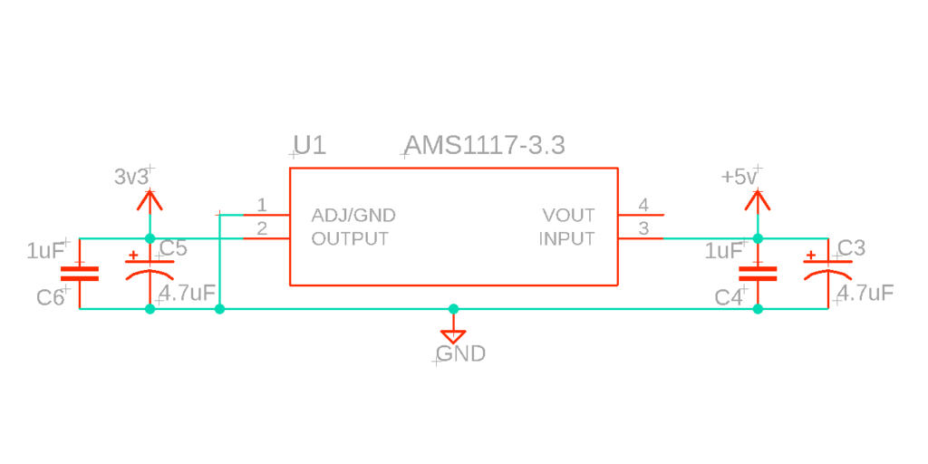
The 5v from the USB input is given to this AMS1117-3.3 IC, which is a 3.3v voltage regulator. Its job is to regulate the output power to a certain voltage level, which is safe for those microcontrollers.
Step 2: Circuit Connection


Then you need to hook up the microcontroller. To do that, you need to connect pins in the following manner,
Step 3: Power it Up


Then connect the USB to serial converter to the computer via USB. Some modules have a male USB type-A socket, which you can directly plug into the USB port of the computer, while some use a micro-USB port, and you will need a standard USB cable to connect it.
Step 4: Programming

To program the pro mini board, first open up Arduino IDE. Then go to Port under the tools menu. There you should see the COM6 port. So, the device is ready to take commands. Now we need to open an example sketch and press upload.

You will see the onBoard TX and RX LED is blinking, indicating that the code is uploading to the microcontroller since it’s all binary values, so the LEDs turn on and off sequentially. After uploading the code, you can open the serial monitor in the IDE., where you can see if there is any output coming from the Arduino board.
So, this is how the circuit works. Its functioning is straightforward, and it’s also very cheap as compared to the other USB drivers. That is why it is very popular when it comes to making budget-friendly hardware.
If you’re ready to use USB in your next design, download Fusion 360 for access to comprehensive electronics and PCB design tools in one product development platform.
