This post is also available in: English (Inglese)
Computer Aided Manufacturing (CAM): The Complete Introduction for the Beginner’s Mind
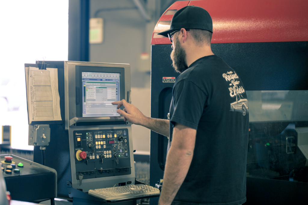
In a world full of physical stuff – whether that’s products, parts, or places – Computer Aided Manufacturing (CAM) makes it all possible. We’re the ones that give the power of flight to airplanes or the rumble of horsepower to automobiles. When you need something made, not just designed, CAM is your answer. What happens behind the scenes? Keep reading, and you’ll find out.
What is CAM? Computer Aided Manufacturing (CAM) is the use of software and computer-controlled machinery to automate a manufacturing process.
Based on that definition, you need three components for a CAM system to function:
- Software that tells a machine how to make a product by generating toolpaths.
- Industrial machinery that can turn raw material into a finished product.
- Post Processing converts toolpaths into a language machines can understand.
These three components are glued together with tons of human labor and skill. As an industry, we’ve spent years building and refining the best manufacturing machinery around. Today, there’s no design too tough for any capable machinist shop to handle.
CAD to CAM Process
Without CAM, there is no CAD. CAD focuses on the design of a product or part. How it looks, how it functions. CAM focuses on how to make it. You can design the most elegant part in your CAD tool, but if you can’t efficiently make it with a CAM system, then you’re better off kicking rocks.
The start of every engineering process begins in the world of CAD. Engineers will make either a 2D or 3D drawing, whether that’s a crankshaft for an automobile, the inner skeleton of a kitchen faucet, or the hidden electronics in a circuit board. In CAD, any design is called a model and contains a set of physical properties that will be used by a CAM system.
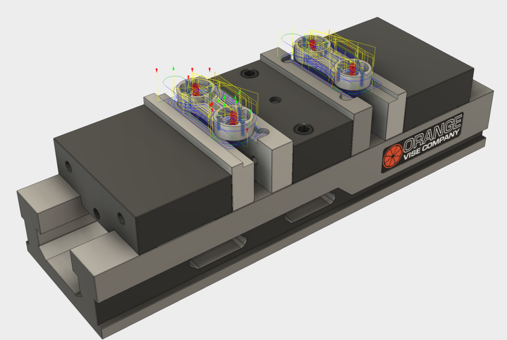
When a design is complete in CAD, it can then be loaded into CAM. This is traditionally done by exporting a CAD file and then importing it into CAM software. If you’re using a tool like Fusion 360, both CAD and CAM exist in the same world, so there’s no import/export required.
Once your CAD model is imported into CAM, the software starts preparing the model for machining. Machining is the controlled process of transforming raw material into a defined shape through actions like cutting, drilling, or boring.
Computer Aided Manfacturing software prepares a model for machining by working through several actions, including:
- Checking if the model has any geometry errors that will impact the manufacturing process.
- Creating a toolpath for the model, a set of coordinates the machine will follow during the machining process.
- Setting any required machine parameters, including cutting speed, voltage, cut/pierce height, etc.
- Configuring nesting where the CAM system will decide the best orientation for a part to maximize machining efficiency.
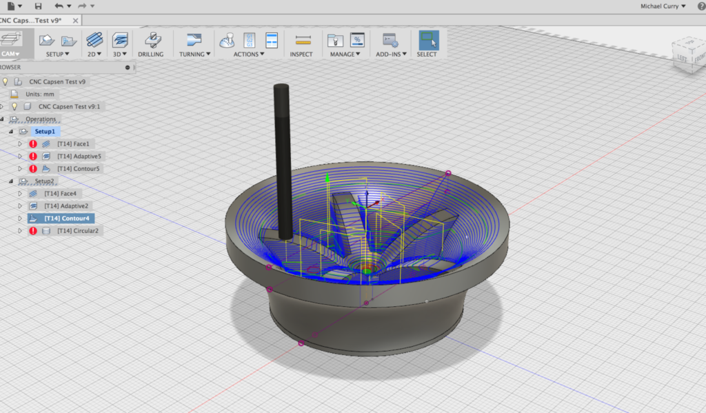
Once the model is prepared for machining, all information gets sent to a machine to produce the part physically. However, we can’t just give a machine a bunch of instructions in English. We need to speak the machine’s language. To do this, we convert all of our machining information to a language called G-code. This is the set of instructions that controls a machine’s actions, including speed, feed rate, coolants, etc.
G-code is easy to read once you understand the format. An example looks like this:
G01 X1 Y1 F20 T01 S500
This breaks down from left to right as:
- G01 indicates a linear move based on coordinates X1 and Y1.
- F20 sets a feed rate, which is the distance the machine travels in one spindle revolution.
- T01 tells the machine to use Tool 1, and S500 sets the spindle speed.

- A more visual way to understand G-code coordinates. Image courtesy of Make:.
Once the G-code is loaded into the machine, and an operator hits start, our job is done. Now it’s time to let the machine do the job of executing G-code to transform a raw material block into a finished product.
CNC Machines at a Glance
Up until this point, we’ve talked about the machinery in a CAM system as simply machines, but that really doesn’t do them justice. Watching a Haas milling machine slide through a block of metal like it’s butter puts a smile on my face every time. Without these machines, my job would be impossible.

- Image courtesy of Haas Automation.
All modern manufacturing centers will be running various Computer Numerical Control (CNC) machines to produce engineered parts. The process of programming a CNC machine to perform specific actions is called CNC machining.
Before CNC machines came to be, manufacturing centers were operated manually by Machinist veterans. Of course, like all things that computers touch, automation soon followed. These days the only human intervention required for running a CNC machine is loading a program, inserting raw material, and then unloading a finished product.
Over at the Autodesk Pier 9 workshop, we have a decent sample of CNC machines, including:
CNC Routers
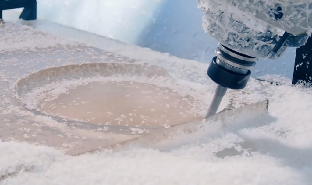
These machines cut parts and carve out a variety of shapes with high-speed spinning components. For example, a CNC router used for woodworking can make easy work of cutting plywood into cabinet parts. It can also easily tackle complex decorative engraving on a door panel. CNC routers have 3-axis cutting capabilities, which allows them to move along the X, Y, and Z axes.
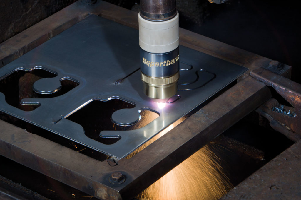
Water, Plasma & Laser Cutters
These machines use precise lasers, high-pressure water, or a plasma torch to perform a controlled cut or engraved finish. Manual engraving techniques can take months to complete by hand, but one of these machines can complete the same work in hours or days. Plasma cutters are handy for cutting through electrically conductive materials like metals.
Milling Machines
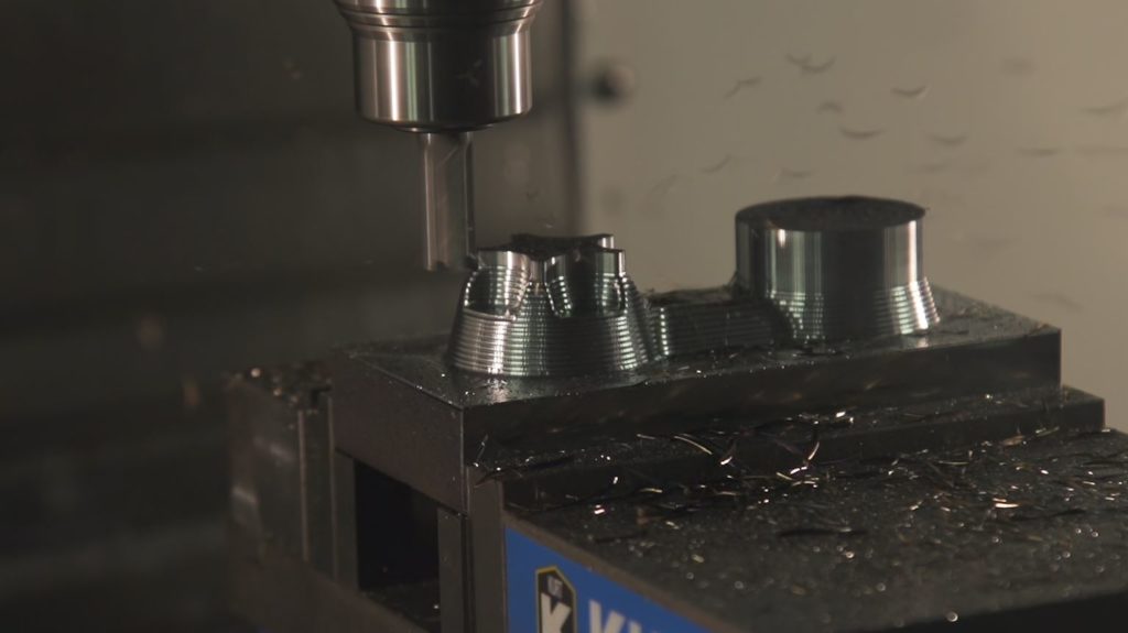
These machines chip away at a variety of materials like metal, wood, composites, etc. Milling machines have enormous versatility with a variety of tools that can accomplish specific material and shape requirements. A milling machine’s overall goal is to remove mass from a raw block of material as efficiently as possible.
Lathes
These machines also chip away at raw materials like a milling machine. They do it differently. A milling machine has a spinning tool and stationary material, where a lathe spins the material and cuts with a stationary tool.

- Image courtesy of Halsey Manufacturing.
Electrical Discharge Machines (EDM)
These machines cut the desired shape out of raw material through an electrical discharge. An electrical spark is created between an electrode and raw material, with the spark’s temperature reaching 8,000 to 12,000 degrees Celsius. This allows an EDM to melt through nearly anything in a controlled and ultra-precise process.

- Image courtesy of Absolute Wire EDM.
The Human Element of Computer Aided Manufacturing (CAM)
The human element has always been a touchy subject since CAM arrived on the scene in the 1990s. In the 1950s, when John T. Parsons first introduced CNC machining, skillfully operating machines required an enormous amount of training and practice. The video below from NYC CNC shows a great example of how different manual machines are from today’s CNC machines:
In manual machining days, being a Machinist was a badge of honor that took years of training to perfect. A Machinist had to do it all — read blueprints, know which tools to use, define feeds and speeds for specific materials, and carefully cut a part by hand. It wasn’t just about precise manual dexterity. Being a Machinist was, and still is, both an art and a science.

- Image courtesy of ITABC.CA
These days, the Modern Machinist is alive and well as human, machine, and software combine to move our industry forward. Skills that used to take 40 years to master can now be conquered in a fraction of the time. New machines and CAM software have given us more control than ever to design and make better and more innovative products than our forefathers, which they’ll admit…begrudgingly.
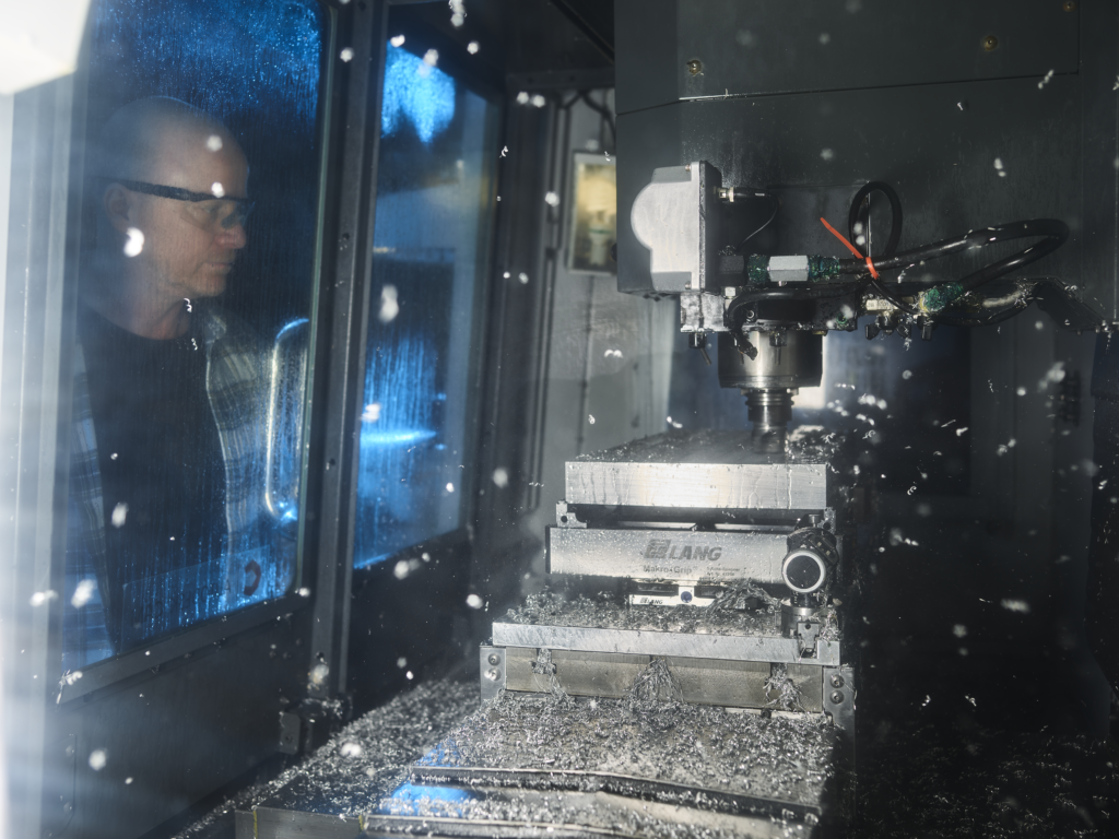
What does all this mean for the human element of manufacturing? The role of a Traditional Machinist is shifting. Today we’re seeing an environment of Modern Machinists played out with three typical roles:
- The Operator. This individual loads raw materials into a CNC machine and runs completed parts through the final packaging process.
- The Setup Operator. This individual performs the initial configuration for a CNC machine, including loading a G-code program and setting up tools.
- The Programmer. This individual takes the drawing for a CAD model and decides how to make it with their available CNC machines. Their job is to define the toolpaths, tools, speeds and feeds in the G-code to get the job done.
In a typical workflow, the Programmer will hand off his program to the Setup Operator, who will then load the G-code into the machine. Once the machine is ready to roll, the Operator will then make the part. In some shops, these roles might combine and overlap into the responsibilities of one or two people.
Outside of day-to-day machine operations, there is also the Manufacturing Engineer on staff. In a new shop setup, this individual typically establishes systems and determines an ideal manufacturing process. For existing setups, a Manufacturing Engineer will monitor equipment and product quality while handling other managerial tasks.
The Impact of CAM
We have John T. Parsons to thank for introducing a punch card method to program and automate machinery. In 1949 the United States Air Force funded Parsons to build an automated machine that could outperform manual NC machines. With some help from MIT, Parsons was able to develop the first NC prototype.
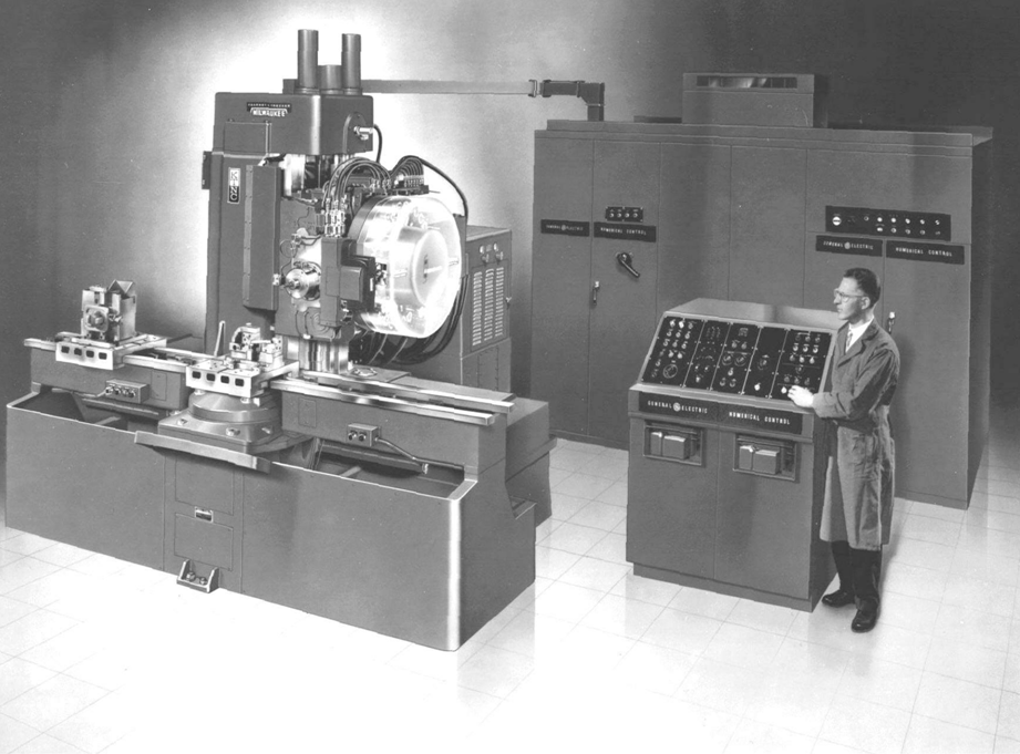
From there, the world of CNC machining started to take off. In the 1950s, the United States Army bought NC machines and loaned them out to manufacturers. The idea was to incentivize companies to adopt the new technology into their manufacturing process. During this time, we also saw MIT develop the first universal programming language for CNC machines: G-code.

The 1990s brought CAD and CAM’s introduction to the PC and has completely revolutionized how we approach manufacturing today. The earliest CAD and CAM jobs were reserved for expensive automotive and aerospace applications, but today software like Fusion 360 is available for manufacturing shops of any shape and size.
Since its inception, CAM has delivered a ton of improvements to the manufacturing process, including:
- Improved machine capabilities. CAM systems can take advantage of advanced 5-axis machinery to deliver more sophisticated and higher quality parts.
- Improved machine efficiency. Today’s CAM software provides high-speed machine tool paths that help us manufacture parts faster than ever.
- Improved material usage. With additive machinery and CAM systems, we can produce complex geometries with minimal waste, which means lower costs.
Of course, these benefits have some trade-offs. Computer Aided Manufacturing systems and machinery require a massive upfront cost. For example, a Haas VF-1 costs about $45k out the door; now imagine an entire shop floor of those. There’s also the problem of turnover. With machine operation becoming less of a skilled trade, it’s tough to attract and retain good talent.
CAM is the Man
CAM isn’t just about controlling machines on a shop floor. It’s about bringing together software, machines, processes, and people to build really great parts. If this is your first time diving into the world of CAM, I highly encourage you to reach out to a local shop to get an inside tour. Feel the hum of the CNC machines in your feet, or slide your hand across a part fresh out of the machine. It’s an incredible experience that I hope future generations get to enjoy. CAM is all about the human touch.
Are you still dinking around with a separate CAD and CAM tool? Fusion 360 has both. Try Fusion 360 today.

