Elevate your design and manufacturing processes with Autodesk Fusion
This post is also available in: Français (フランス語) Italiano (イタリア語) Deutsch (ドイツ語) English (英語)
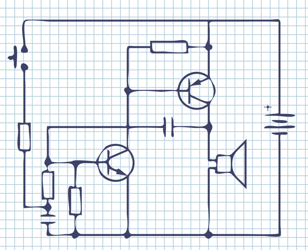
Understanding the basics of electronics can be a daunting task for some people, while others find it very easy to grasp current and voltage concepts. This guide will take you through each of the basic concepts of electronics one at a time, and make sure that you understand and get an insight into each of the topics without getting bored. So, let’s get started!
Basic Terminology
Before delving into the basic terminology, you must know what charges are. There are two types of charges; positive and negative. Like charges repel, while unlike charges attract. Every atom has positive and negative charges. Positive charges are inside the nucleus and are called protons, while negative charges, called electrons, are in orbits surrounding the nucleus.

These electrons either stay inside the orbits or move as free/mobile electrons, depending on the type of element they belong to. If you look at the periodic table, notice that the elements are divided into three categories; metals, semiconductors, and non-metals. Metallic elements have mobile electrons, which is why they are called conductors, while non-metals hold on to their electrons tightly—therefore making them poor conductors.
Current
What is current, then? It is the rate of flow of charges, which means that if you count the number of charges passing through a point inside a wire, in one second, then you will get the amount of current flowing through it.
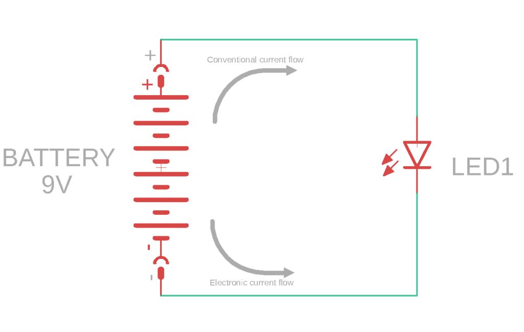
What is the direction of current flow in a circuit? The path in which electrons flow is referred to as electric current, while the conventional is in the opposite direction. You may say that it is the flow of positive charges. Within a circuit, the conventional current path is from the positive end of the battery to the negative end, as shown in the diagram below.
Voltage
The difference in charge between two points is defined as voltage. To understand it better, consider the energy analogy. If a ball is present on top of a hill, it has a high amount of potential energy compared to what is left after it rolls down and reaches the bottom. Along the way, the ball loses power in exchange for some work done. Similarly, electrons experience a change in energy as they move through a circuit. The difference in their energy between two points is termed as voltage.
Ohm’s law relates voltage and current in a circuit. Here is what it states:
V=IR
Where V is the Voltage in Volts, I is the current in Amperes, and R is the resistance in Ohms.
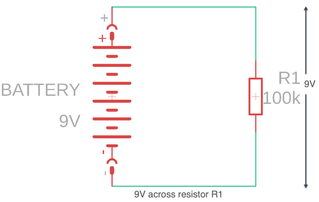
We will look at resistors in detail in the next section. The circuit below demonstrates how voltage is measured between two points across a resistor.
Power
Generally, power is defined as the rate of energy transfer. We all know that energy can not be destroyed, but it can be transformed from one form to another. For example, potential energy is converted into kinetic energy when a rock rolls down a hill; how fast this transfer takes place is another way to measure power.
In electronics, electrical energy is converted to other forms of energy, and vice versa. For example, when a battery supplies power, chemical energy converts into electrical energy. Similarly, a bulb lights up as a result of converting electrical energy into light energy.
To sum it up, we can say that electric power is the rate of transfer of electrical energy. Mathematically speaking, power is the product of voltage and current, and is represented as:
P=VI
Where P is the power in Watts, V is the voltage in Volts and, I is the current in Amperes.
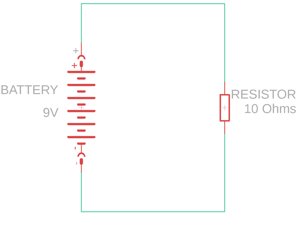
Consider the circuit shown above. We can calculate the power consumed by the load by using the equation mentioned above. We need to know the values of voltage and current. For computing the current, we will use Ohm’s law. Rearranging the Ohm’s law equation, we get:
I= V/R
= 9V/10Ω =0.9 A
Now we can compute the power dissipated by the resistor is:
P=VI
=(9)(0.9)
P=8.1 W
The power dissipated by the 10Ω resistor turns out to be 8.1 Watts, which is the transfer rate of electrical energy in this circuit.
AC and DC
You must have heard that there are two types of circuits; AC and DC. What are AC and DC? How can you differentiate between these terms?
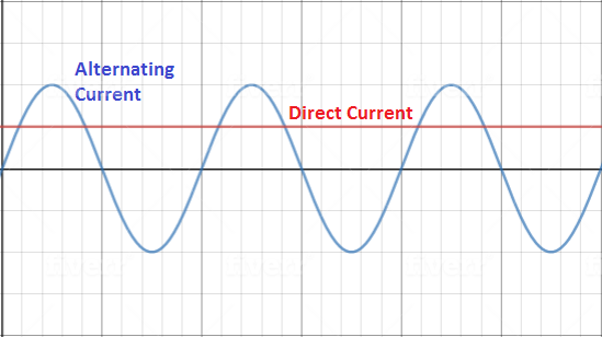
AC stands for “Alternating Current” while DC stands for “Direct Current.” In DC circuits, current flows in only one direction while in AC circuits, it changes its direction after a fixed interval of time. This allows both circuits to exhibit different properties and serve various applications.
DC is mostly used in digital and logic circuits, while AC is present in our home’s electrical system. Since alternating current changes its direction periodically, it is represented as a sine wave with a particular frequency and amplitude. Direct current is described as a constant level, a straight line, since it does not vary.
Common Circuit Elements
Now that you have understood the basic vocabulary of electronics, let’s look at some common circuit elements and see how they work.
Resistors
A resistor is an essential element of an electronic circuit. It offers opposition to the flow of current, which is governed by Ohm’s law, and this opposing force helps designers set current values in the circuit as per their requirements. For instance, if you are working on a circuit that needs less current, you would have to introduce a high resistance value in your circuit.
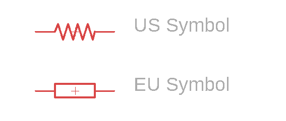
Schematic Symbol Representations
Types of Resistor Packages
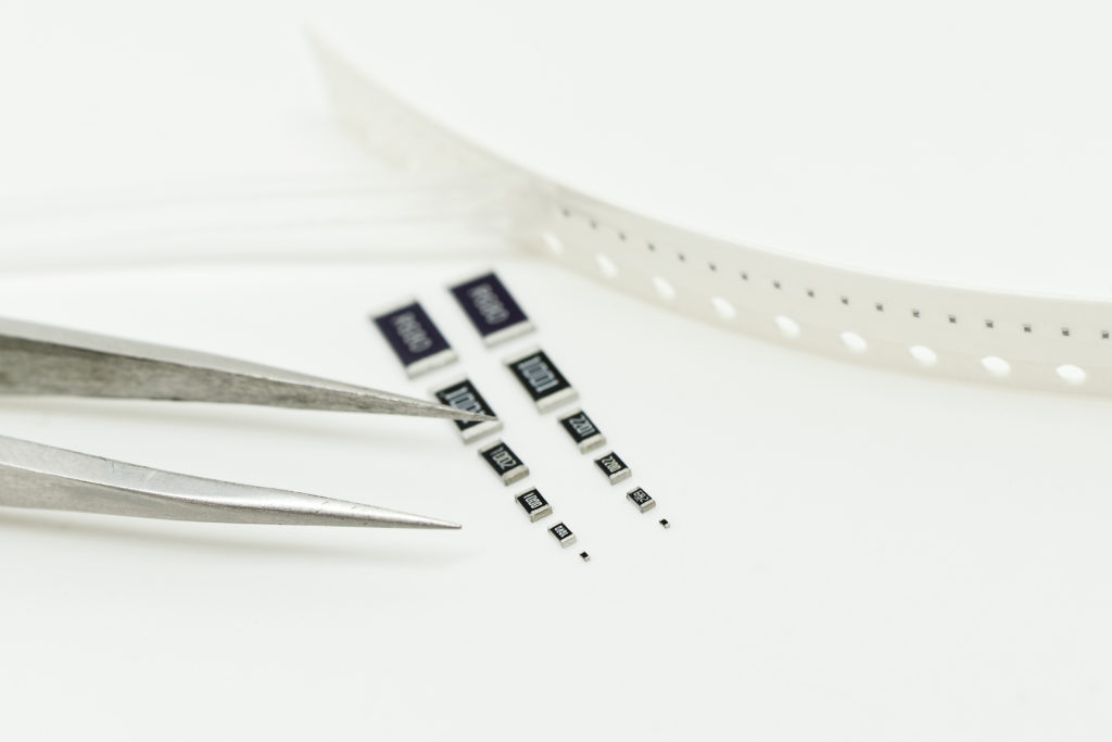
Resistors come in different types of packages. They can be categorized as SMD (Surface Mount Device) and Axial resistors. SMD resistors are commonly used in PCBs and designing electronic equipment. These resistors are distinguished by a numerical code, referred to as an imperial code, which refers to the SMD resistor’s dimensions.
Some common SMD resistor examples are 0603 and 0805. 0603 converts to a length of 0.06 inches, and a width of 0.03 inches. Similarly, the code 0805 translates to a length of 0.08 inches, and a width of 0.05 inches. The SMD resistor sizes convert to different power ratings, for instance, the 0603 resistor has a rating of 0.10 Watts while 0805 has a rating of 0.125 Watts. Other imperial codes include 0201, 0402, 1206, 1210, 1812, 2010 and 2512.
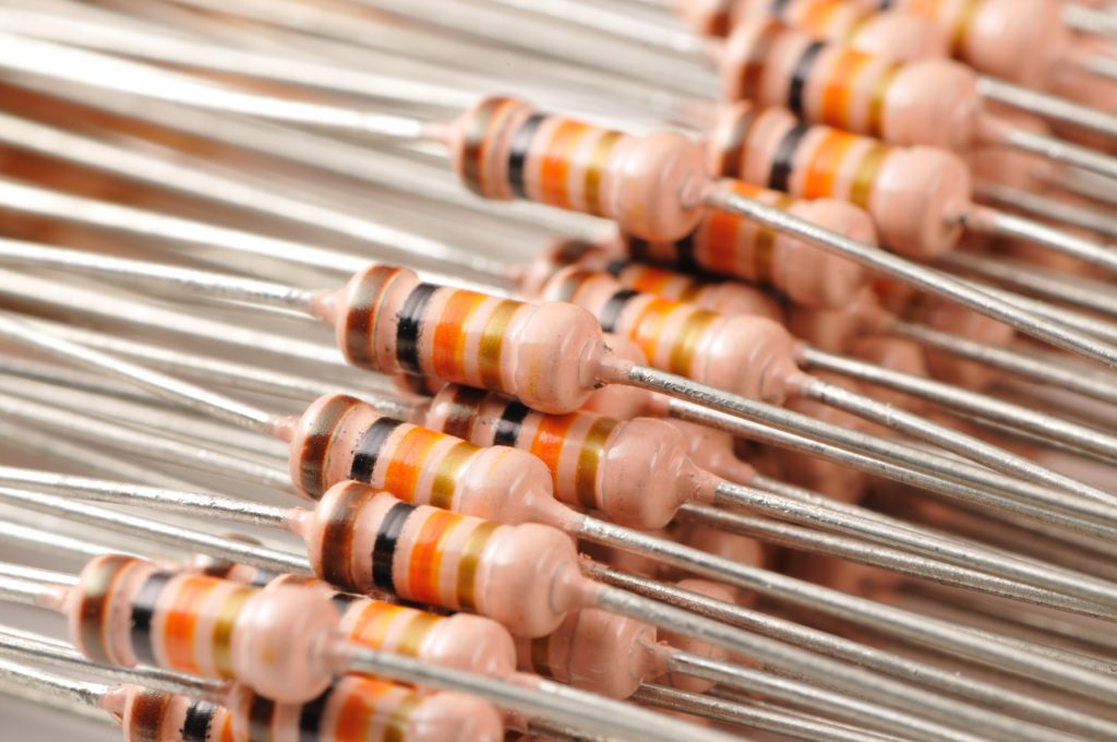
On the other hand, the cylindrical-shaped resistors commonly used by students and hobbyists are the axial resistors. They have a color-coding scheme, which allows us to determine the resistance value without having to measure it with a multimeter. Axial resistors come in different types, including carbon film, metal film, wire round, and carbon composition.
Color Coding
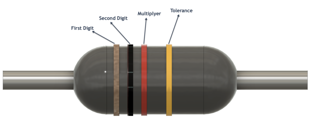
The resistor color coding scheme might seem a bit difficult for you at first, but as you dive deep into electronics, you will find it very easy to interpret. Each axial resistor has four color bands, three of which tell the resistance value, and the fourth one indicates the tolerance value of the resistor and is of either silver or golden color.
While reading the resistance value, always keep the tolerance band on your right side and read the colors from the left side. The table below shows the value each color represents.
| Color | Digit |
Multiplier | Tolerance (%) |
| Black | 0 | 100 | |
| Brown | 1 | 101 | 1 |
| Red | 2 | 102 | 2 |
| Orange | 3 | 103 | |
| Yellow | 4 | 104 | |
| Green | 5 | 105 | 0.5 |
| Blue | 6 | 106 | 0.25 |
| Violet | 7 | 107 | 0.1 |
| Grey | 8 | 108 | |
| White | 9 | 109 | |
| Gold | 10-1 | 5 | |
| Silver | 10-2 | 10 | |
| None | 20 |
Consider a resistor that has brown, black, orange, and gold-colored stripes. To decode its resistance value, let’s look at the table above. Brown corresponds to the first digit, i.e., 1, black translates to 0, which is the second digit. This makes it 10. Then, orange represents the multiplier; 103, and gold represents 5% tolerance. This creates a resistance value of 10kΩ with 5% tolerance.
Parallel vs. Series Connection
You can connect two or more resistors in two main ways; series and parallel. Series connection is when you connect two resistors one after the other, while a parallel connection is when you connect the ends of a resistor to the ends of another resistor. The circuit diagrams below show how you can connect two resistors in series and parallel.
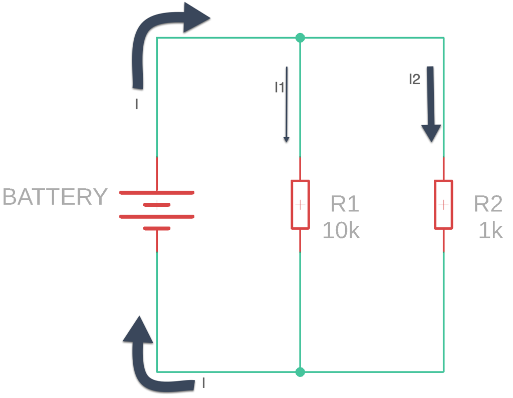
In a parallel connection, the current I, coming from the battery, is divided into two currents I1 and I2. After passing through the parallel resistors, these separate currents join again to form the current I, which heads back into the battery. The voltage across both resistors remains the same. So, you should remember that in parallel connection of resistors, current divides, while voltage remains the same.
The total value of resistance in the case of parallel resistors is calculated using the following formula:
R(total)= (1/R1+1/R2)^-1
In the figure above, we have resistors R1 and R2 of values 10kΩ and 1kΩ, respectively. We can calculate the total resistance as:
R(total)= (1/110k+1/11k)^-1
R(total)= ((10k+1k)/10k)^-1
R(total)= (11k/10k)^-1
R(total)= (10k/11k)
R(total)= 0.9kΩ
However, in a series connection, the current flowing through the resistors remains the same while the voltage divides. The total value of resistance in series can be calculated by simply adding up the individual resistance values.
R(total)=R1+R2
Using the values present in the circuit diagram, we can calculate the total resistance as:
R(total)=10k+1k
R(total)=11kΩ
Capacitors
The second most common element in electronic circuits is a capacitor. It is a charge storing device, made of two parallel metal plates separated by a dielectric layer. The metal plates are oppositely charged and have the capacity to store charges. Capacitors are commonly used for coupling and decoupling purposes, as a charge reservoir, and to provide a smoothing effect to voltage waveforms.
There are two types of capacitors, polarized and non-polarized. You need to connect polarized capacitors in a way that compliments their polarity. One of their legs is marked with a “+” sign while the other is marked with a “– “symbol. The positive leg of a capacitor must always connect to the positive end of a power supply. The negative leg must join with the negative terminal of the power supply.
Parallel vs. Series Connection
Like resistors, you can also connect capacitors in series or parallel, depending on your application. Capacitance is measured in Farads, and the total value of capacitance varies differently in both configurations. Let’s look at each of the settings one-by-one.
To calculate the total capacitance of capacitors in parallel, we simply add up the values.
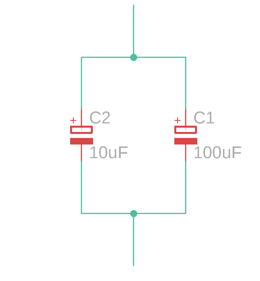
C(total)=C1+C2
C(total)=100μF+10μF
C(total)=110μF
However, suppose the capacitors are connected in series. In that case, their capacitance values are first inverted, then added, and then reciprocated again, just like we calculate resistors’ resistance in parallel.
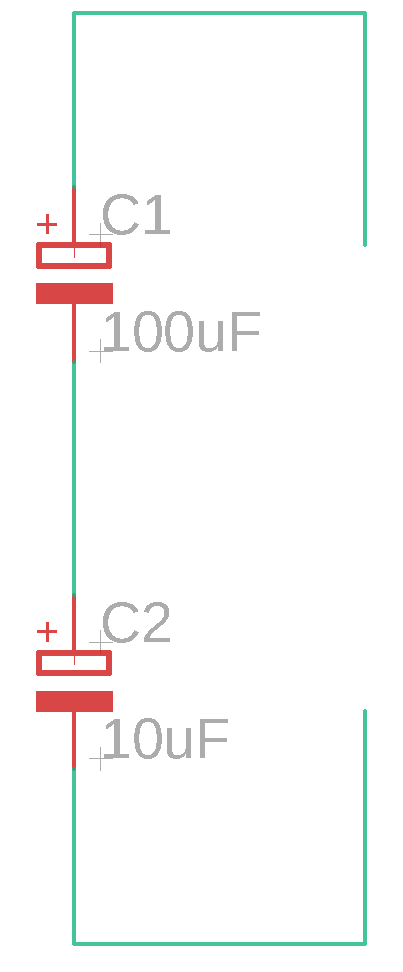
C(total)= (1/C1+1/C2)^-1
C(total)= (1/100μF+1/10μF)^-1
C(total)= (11μ/100μ)^-1
C(total)= 100/11
C(total)=9.09uF
Through-hole vs. SMD
Electronic components come in different types of packages, and the main ones are through-hole and SMD. You can fix through-hole parts on breadboards and protoboards since they have long conducting legs which can be easily inserted. That’s why they are called through-hole devices. On the other hand, Surface Mount Devices (SMD) are used on PCBs and electronic devices such as microcontroller boards. SMD components are much usually much smaller than through-hole components and only occupy one side of the circuit board. Therefore, by using SMD components, you can design smaller designs.
What Is a Circuit?
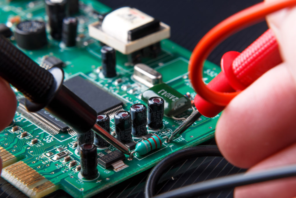
When you join multiple electronic components and connect them to an AC or DC power supply, you get a circuit. That doesn’t mean you start connecting circuit elements without knowing their power ratings, because that way, you will probably end up with an explosive situation. Formally speaking, a circuit is a combination of electronic components connected by conducting wires, where an electric current can flow.
Building a Circuit
What does it take to build a simple electronic circuit? Do you need an engineering degree for that? Of course not! You can learn how to build a simple circuit in a few easy steps.
First, you need to decide which power source you would use. After that, you need to select your circuit components and figure out how you will join them.
For example, we are building an amplifier circuit, which uses an LM386 IC, along with some resistors and capacitors. A 9V DC battery powers the circuit. The output is received at the speaker, which is an amplified version of the input signal. The capacitors in this circuit are used for a variety of purposes. In some places they block DC and couple the signal from input to output, in others they supply extra current keeping the supply voltage from sagging, keeping the 9V smooth under heavy loads, In some cases, they are used as to filter undesired frequencies.
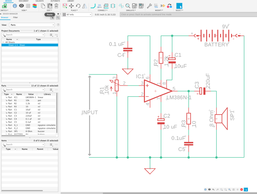
Try this yourself. Use Fusion 360 to create this circuit and impress your friends and colleges on all your new-found knowledge on electronics design. Are you not using Fusion 360 yet? Download today.


