
- 1/22/2021 – Some of you told us that when non-ASCII characters were used on the tool description such as ÄÖÜäöü in German or Ą Ć Ę Ł Ó Ś Ż Ź in Polish and Czech language, the Kernal fails to calculate the toolpath. French and Italian UI versions also affected. Sorry about that – this has now been fixed.
We also fixed a related issue where non-standard characters in jobfiles caused a kernel error, which sometimes resulted crash.
–
- 1/21/2021 – If you were unable to save changes made to you documents, after the last update, then restart Fusion 360 again and take the latest fix. We found the culprit and now this issue has been resolved. Thank you all for commenting and letting us know.
–
Last week, we looked at our 2020 year-in-review and shared some of the key projects we’re working on this year. Now, we’re starting to make good progress on some of those projects. Check out what’s new in this product update.
Note: 10 Document Limit for Personal Use Offering
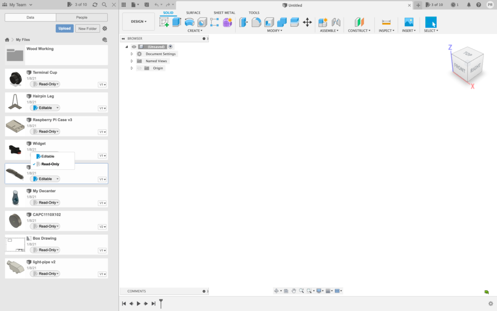
In mid-October of 2020, we announced that we were going to make some changes to the Fusion 360 for Personal Use offering. Most of the changes mentioned in that announcement have already been made, and in this update, the 10 document limit change is now also in effect.
This means that if you are using the free Personal Use offering (which will remain free), there is a limit on how many documents are “Editable” at the same time. The rest of your documents are set as “Read-Only”, and you can mark them as “Editable” as you see fit. Once you’ve reached 10 out of 10 and want to mark more as “Editable”, you’ll need to mark one of the “Editable” ones as “Read-Only” to make room. You can still create or upload as many documents as you want; there is no limit to that. The limit applies to how many documents are “Editable” at the same time.
In response to all the questions around how the experience would play out, we made a detailed blog post explaining what to expect, describing everything around what’s new, what the interactions will be, to how you can manage your documents. If this change affects you, be sure to check out the blog post for details.
Learn more about the 10 Document Limit
Usability
New! Notifications Center

When you upgraded to this product update, you may have noticed something was different yet also familiar. The green update banner no longer appeared, and instead, a new notification greeted you to the latest update, now located in our new notification center in the top-right corner. This will be the place where you will be notified of data translation status, update success, and much more. We will be making continual improvements to this notification center, so that you get the news you need to know, without taking up additional design real-estate.
–
Improved! Extensions icon is now a plug icon

After talking to many of you, we learned that the wrench icon we used for Extensions was causing confusion on what it actually meant. That’s why we’ve now updated the icon to a plug icon. This icon will also appear on tools that belong to an extension pack, such as Generative Design Extension, Machining Extension, and Additive Simulation Extension.
–
New in preview! High DPI Scaling for Windows machines
Preferences > Preview Features > High DPI Scaling

If you have been using Fusion 360 on a Windows machine with an high DPI display, you may have experienced some UI scaling issues in the past. We’ve been working improving Fusion 360’s scaling performance, and are happy to you can now try a new preview feature that will enable your Fusion 360 to scale accordingly.
Since this is still a preview, we are still ironing out some kinks. The scaling preview today works best at 200% DPI Scale or higher. Setting your UI at 125%, 150%, or 175% scale may make it appear disproportionate. The application window may also move offscreen while it resizes into these specific percentage scales. If you try this preview, we’d love to hear your feedback. We have a plan set in place for improving our scaling performance, and your feedback will help guide us in the right direction.
Learn more about High DPI Scaling
–
[expand title=”See notable fixes”]
- Now if you have “Use high resolution graphics” option turned on under Graphics section of your Preferences, you can now also go to Display Settings > Effects in the Nav Bar and turn on/off Anti-Aliasing and/or Ambient Occlusion.
- Igorva, among a few others, have told us that when they tried to download the Photobooth rendering environment, their Fusion 360 decided to overthink the task and freeze up. We dug into this and found out that it was related the default environment setting in the Preferences. This is now fixed.
- ltomuta told us about an issue he was seeing where he was unable to open a document that he was successfully viewing on Fusion Team. Sorry about that – this has been fixed.
- etfrench noticed that when he viewed his design with the Viewcube Top or Bottom view, the origin lines that were previously visible disappeared for no reason. We swear it’s still there, but you just couldn’t see it. This is now fixed and the origin will always remain visible regardless of viewing angle.
[/expand]
Data Management
Out of preview! Project navigation in Fusion Team

Back in May of 2020, we enabled an optional preview of the new navigation experience for Fusion Team to enable a much smoother and more intuitive workflow. The foundation of this navigation view is setting the stage for many new data and view components that are coming soon, but for now everyone (except those who have still not migrated from the legacy environment) will now see this new navigation experience in the Fusion Team browser client.
Sketching & Modeling
New! Thin Extrude Option
Design workspace > Solid Tab > Create Panel > Extrude > Thin Extrude Option

New for the Extrude command is now an option to create a Thin Extrude. This will allow you to take the original sketch profile and give it a wall thickness instead of a block of material. We have enabled a lot of options for you to use around direction control and positioning of the extrude.

–
New! Untrim Surface tool
Design workspace > Surface Tab > Modify Panel > Untrim Surface

One of the most requested surfacing features by you has been the ability to “Untrim” a surface. We’re happy to report that this update now gives you the ability to create an untrimmed surface from a surface body. You will have the options for how to Untrim the surface: internal, external, all, or manual. This gives you control to get the right untrimmed surface without cumbersome workarounds.

–
New! Isocurve Analysis Tool
Design workspace > Inspect Panel > Isocurve Analysis Tool

We have a new analysis type within Fusion 360, Isocurve Analysis. This analysis type will start to show the flow of a surface. This will allow you to check the surface and make sure the surface is flowing in the correct way but also if the surface blends well with other adjacent surfaces. This should help when tangency and continuity are key to the aesthetics of the design.

Learn more about Isocurve Analysis
–
Improved! Sketch Text now has text spacing as percentages
Create Sketch > Text > Text on path type > Character Spacing

If you’re using the Text on Path feature, you’ll be happy to know that you can now set character spacing for your text (if Fit to Path is unchecked). This enables you to fine tune the spacing between characters and adds more customizability to your designs.
–
Improved! Centerline Linetype option now available in Sketch Palette
Create Sketch > Sketch Palette > Centerline Linetype
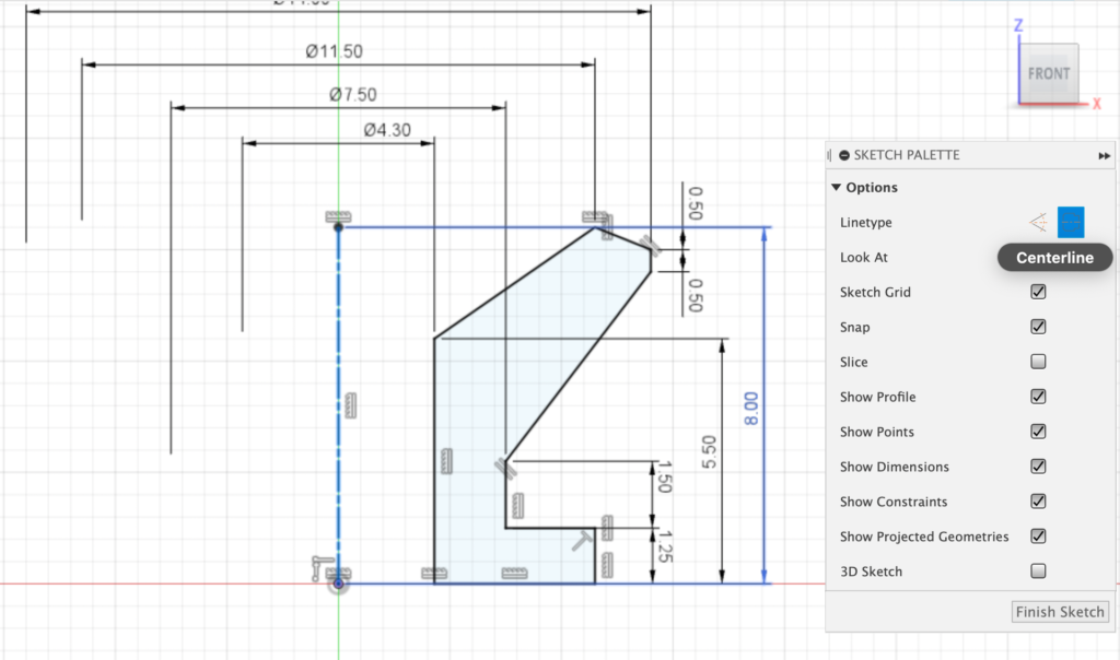
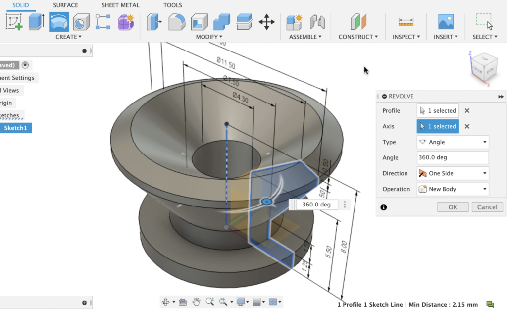
As one of those quality-of-life improvements that will be sure welcomed by many of you, we’ve added the option to turn a sketch line into a Centerline Linetype directly from the Sketch Palette. Along with the Construction Linetype, you can now toggle between one and other without needing to right-click and select it from the marking menu.
–
Improved! Sketch Text settings will be remembered through active session
Previously, your Sketch Text settings used for a particular sketch only applied to that sketch. These settings are now remembered throughout your active session of Fusion 360, so that you can spend less time on messing with the settings and more time on creating the text itself.
–
[expand title=”See notable fixes”]
- HughesTooling spotted a weird UI bug in the Hole command dialog where the leader lines indicating the dimension of the hole type within the command dialog was encroaching the input field. Now the lines should appear as designed.
- HughesTooling also told us about an issue where moving features into a sub component and then proceeding to edit a Sweep action caused Fusion 360 to crash. We were able to reproduce this and found the culprit. This workflow will no longer cause instability.
- OceanHydroAU noticed an odd behavior in the Rectangular Pattern tool where if you filled the number of instances first and then selected the direction last, it wipes out the previous inputs. Sorry about that – this is now fixed.
- Some of you reported issues with the Parameters functionality where values being produced by the parameter equations were different when compared to the Model parameters. Apparently Fusion 360 got some of the math mixed up. Now everything should check out.
- manish.ingale found a bug in Surface Trim tool where some selected geometry like points and faces will still trim even through it was not highlighted in red. Our own Jeff Strater was able to reproduce this issue and we’re happy to report that this issue has been resolved.
- jonwienke and a few other members of the community noticed that some when they perform a Revolve or Extrude action on certain sketch profiles, the profile gets lost for no apparent reason. We dug into the code and found some wonkiness around 2D and 3D sketch behaviors. This is now fixed.
[/expand]
Electronics
New! Package Generator now has a separate tab for Footprint customization
File > Electronics Library Editor > Create New Package
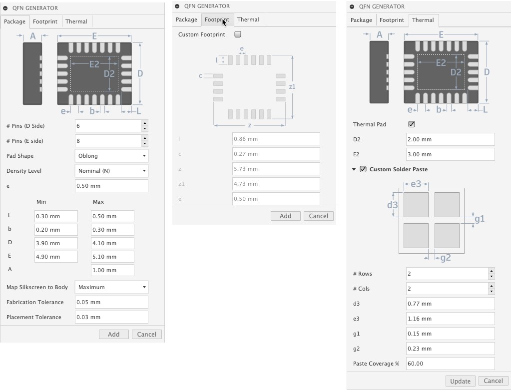
Aligning with the native Fusion 360 interface experience, The Footprint tab now makes it easier to differentiate between 3D component generator and the 2D footprint parameters. This also allows you to better focus on creating custom footprints if needed.
–
New! Package generator now supports customizing footprint pads for all through-hole package types
File > New Electronics Library > Create a New Package

We have extended the SMD pad customization option to all through-hole parts. The new Footprint tab allows you to customize through-hole pad stacks according to your own guidelines or follow the manufacturer’s datasheet.
–
New! Additional libraries and parts now available
File > New Electronic Design > Schematic > Add Part
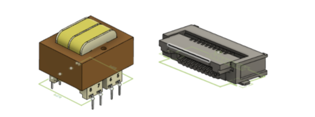
New year, new libraries and parts! This update includes a new library of Transformers as well as some new connector parts in the connector library.
–
New! Re-use Device pin-pad mapping from available devices to other device variants
File > New Electronics Library > Device Editor
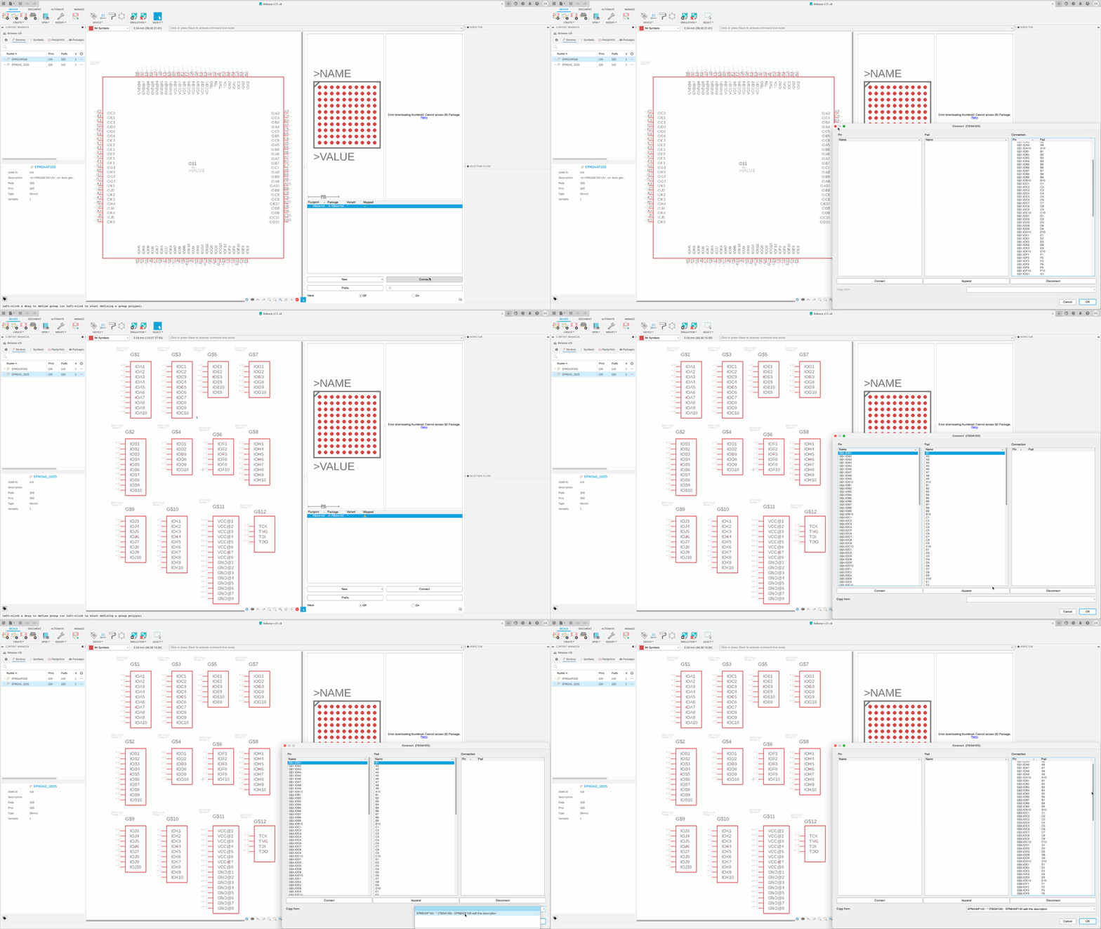
It is not uncommon that you will be using electronic devices that have 10 to 1000 connecting point.
The process of building a component will require that you map all your symbol pins to their respective pads. With small pin count devices, this task can be accomplished relatively fast. But when working with FPGA or BGA’s with a large number of pads, mapping the pin to the pads is a time-consuming task.
With this new feature you can build a device with a single symbol or multiple symbols and re-use the existing pin-pad mapping. This is a huge time saver when working with components with large pin counts. The main advantage of this is that it makes it easy to split a large BGA symbol into multiple gates. Often pre-made parts just give a single monolithic symbol, with this feature you can make your own symbol configuration and re-use the mapping.
–
New! Preference for Electronic Grid Settings
Preferences > Electronics > Reset Grid

With this new option, you can have the grid reset to the default values when you load your designs or continue to work with the grid setting you have been using. The default setup has the schematic grid resetting to the default grid.
–
[expand title=”See notable fixes”]
- christopher2KLSVU, maustinQZ9FZ and ryantgolden have reported a nasty bug that was causing their 2d PCB data to disappear when they encountered an error dialog upon saving the 2D PCB design. We dug into the codebase and found the issue – this is now fixed.
- phaggren told us about a crash issue where his 3D PCB would not display, and Fusion 360 would get bogged down trying to compute more Hole command actions than needed. Since phaggren was sending his Crash Error Reports, we were able to pinpoint the problem. This bug is now squashed for good.
- erik.hole experienced an inconsistency in how the 3D PCB soldermask was being shown. He pointed out that solder mask of the 3D the solder mask was supposed to be white with black silk screen, but showed up as black in the 3D PCB viewer. We made a few tweaks to our graphics engine and now it should be consistent.
- We fixed an issue related to uploading specific assembly documents (f3z), where some of you were getting an “Error reading file” error message.
[/expand]
Simulation
Improved! Extended support for Send to Ansys workflows
Simulation > Ansys Tab
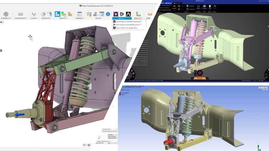
Over the past year, we have continued to work to expand our partnership with Ansys. Last year, in our January 2020 update, we released workflows that would allow you to take generative design outcomes and the associated linear static stress setup to Ansys Mechanical and Discovery with the click of a button. In this release, we are expanding this functionality to allow you to send any Fusion 360 design, part or assembly and with or without generative components, to Ansys Mechanical and Discovery 2021 R1 from the Simulation workspace. Further, we have expanded this workflow to allow for transferring study information from Modal Frequencies, Linear Buckling, Nonlinear Static Stress, Thermal and Thermal Stress studies.
Learn more about sending setups directly to Ansys or exporting an Ansys setup file.
To learn more about using Fusion 360 and Ansys products together:
- Simulate Anything: Fusion 360 and Ansys Interoperability
- Innovate Faster: Capitalize On the Autodesk and Ansys Technology Partnership
Drawing
New! Taper & Slope Symbols
Drawings workspace > Symbols Panel > Taper & Slope
We added weld symbols in December, and now we are adding Taper & Slope! As with other mechanical engineering symbology this new symbol conforms to ASME or ISO standards, depending on your drawing setup.


–
New in preview! – Broken Views
Preferences > Preview Features > Drawing > Break View
Those of you with long or tall parts and assemblies can now display them as a broken view! We are so excited to get this feature to you that we are releasing it early as a Preview, so first head to your Preferences, then choose Preview Features, and turn on Break View.

Once you’ve turned on the Preview feature you will find a new toolbar button near the Drawing Views. Start the command, choose a view, then place the two locations where you want to break your model.

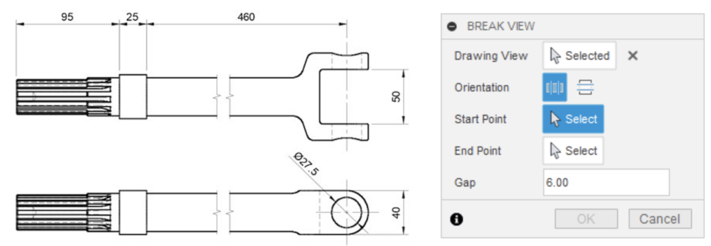
You can add a break to a base view, edit the break, and adjust the spacing between the two “halves” of your view. Your “break” can be either horizontal or vertical. You can add a dimension “across” the break and it displays the correct value. There are some known limitations with this feature-in-preview. We are very interested in your feedback on this preview feature. We have posted a brief list of what is working, and where the feature still needs improvement, on the forum. Comments, questions, and bug reports can be reported in replies to this forum post, and the feature list is included in that forum thread.
–
Improved! Document settings now update Hole & Thread Notes
Many of you have told us that you when you make changes to your document settings for your drawings, you also want those changes to update your Hole & Thread Notes. We totally agree, and now, changes to your Document Settings are applied to existing and new Hole & Thread notes.
–
[expand title=”See notable fixes”]
- Preference Setting will no longer override Projection Angle from Templates
When you create a new drawing from a template, the new drawing should honor all settings configured within the template including projection angle. Previously, this was not the case, due to a bug that was causing the template projection angle to be overridden by the projection angle set in your preferences. Now, the projection angle from the template will be maintained, and should not get overridden by the current projection angle in the Preferences. This change will only impact new drawings. - Issue with slow performance fixed
Our support team told us about a few cases where you were experiencing extremely slow performance while opening and editing certain Fusion 360 drawings. We tweaked how Fusion 360 handles these operations, and are happy to report that the performance of creating / opening drawings, switching between sheets, as well as creating tables has drastically improved and is no longer a bottleneck.
[/expand]
Manufacture
New! Tilt and Turn Graphical handles (Extension Feature)
Manufacture Workspace > Milling > Toolpath Strategy Form > Geometry Tab > Tool Orientation > Turn and Tilt
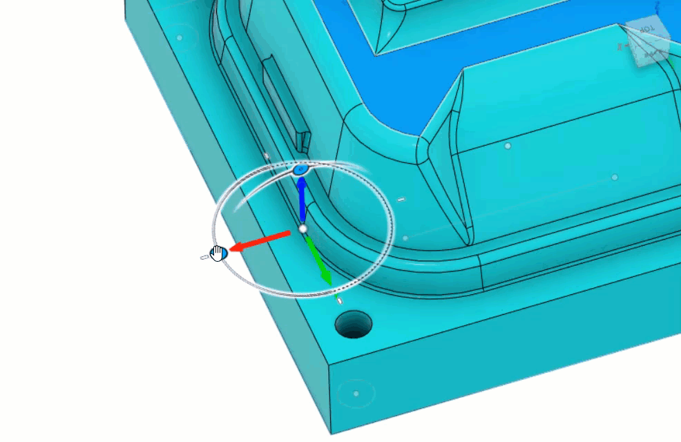
Previously available in preview, new graphical controls, Turn and Tilt, have been added into the Tool Orientation section of the toolpath strategy form. These allow you to adjust the Tool Orientation directly in canvas and are very useful when you can’t use existing geometry to define the Tool Orientation you need. There are also new options to align the Tool Orientation to the normal to a point on a non-planar surface or normal to the current view orientation.
–
[expand title=”See notable fixes”]
- We fixed a few issues that was impacting the 2D Pocket strategy. Some of you have told us that the 2D Pocket operation was not creating a complete contour, and that some faces of the geometry selected were not showing up as selections. These issues have been resolved.
- With an updated kernel, we also addressed a “No dragging” issue found in profile finish, where it was changing the cutting direction.
- The updated kernel also fixes a Roughing Profile canned cycle issue where it was dove Z to stock bottom instead of the toolpath bottom.
- When selecting the output folder option in the Post Processor dialogue window, you can change the location from the default folder. When you actually clicked OK to complete the post processor dialogue, nothing happened. If you leave it set to the default folder location then a windows explorer save file window pops up and lets you save the file as usual. We ironed out the kinks and now you should be able to save it to wherever you want.
- We fixed an issue where operation ordering wouldn’t work as expected when you had a pattern within another pattern in the browser. To benefit from the fix, in Preferences > Preview, select the Bottom-up Pattern Unfolding preview checkbox. Note that this doesn’t currently work with manual NC entries in the patterns or with toolpaths that have a trim modification applied to them.
- If yo are actively using AnyCAD based workflows, you may have ran into an issue where the “Models” folder that lives in the design browser didn’t respond to your clicks when you tried to open it in the Manufacture workspace. Now it does.
- matthew.c.rose told us about an issue where Fusion 360 was giving him an error, telling him that it was not able to generate the toolpath he had created. He was later able to work around the issue by setting is Outer Corner Mode to roll around corner. Now the default for outer corner mode is ‘roll around corner’.
- We also fixed an issue with certain turning profile finishing toolpaths failing to generate.
[/expand]
Additive
New! Support for additional Creality, and Geeetech 3D Printers
Manufacture > Additive tab > Machine Library

We conducted an in-product 3D printing survey during December 2020. The responses we received showed that a good percentage of Fusion users had access to Creality 3D printers that we were not yet supporting with the software. To address this gap, Fusion Machine Library now includes several new Creality (CR10 MAX, CR10 S5, CR10 V2, CR10 V3, CR10S PRO, CR10S PRO V2, Ender 3 V2, Ender 5, Ender 5 PLUS, Ender 5 PRO), and Geeetech (A10, A20, A30, A30 Pro) 3D printers. The post library also has a post associated with these printers, so you can setup the prints and generate G-Code for your machines.
–
New! Control over when to calculate common 3D printing operations
Preferences> General > Manufacture > Additive

You now have dedicated set of additive manufacturing preferences, which will let you control when to perform certain calculations within an additive setup such as: Automatic orientation for components to identify a suitable part orientation, and Support structure generation for faces and/or parts. For example, if your desired workflow includes adding unique support structures to multiple faces/parts for a metal 3D printing setup, you may find it easier to apply the support structure operations first, and later generate them all at once, instead of automatically generating them at the time of application for each support. The choice is yours.
Learn more about automatic orientation and supports
–
New in Preview! Additive Simulation Extension
Manufacture > Additive tab > Process Simulation Panel
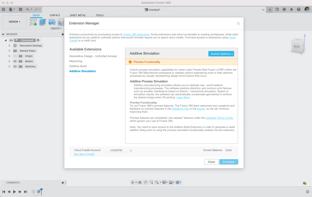
This new extension allows you to simulate what will happen to your parts during the metal laser powder bed fusion 3D printing process. It predicts in-process and post-process distortion and informs you if you will experience interference with the recoater blade during printing. Using this simulation, you can perform what-if studies by testing out different part orientations or support structures. This extension also allows you to generate a compensated geometry in order to reduce distortions and achieve the desired shape when 3D printing. Please note that you will need to have access to the Additive Build Extension in order to benefit from this simulation.

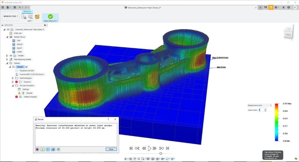
See tutorial on process simulation
–
New in Preview! Automatic update of Posts and Machines
Preferences> Preview Features > Manufacture > Automatically get latest Posts and Machines

With this release, we are also changing how we add new 3D printers and posts to Fusion 360. You will no longer have to wait for a new release of Fusion 360 to get access to the latest version of 3D Printers. Going forward, the list of 3D printers accessible in Fusion will be the same as the one’s available on our online machine library (https://cam.autodesk.com/machineslist). This means each time you restart Fusion 360, you will see the list of available 3D printers in Fusion 360 grow as we upload a new Machine and/or post to our online library.
–
Improved! Additive Setup creation workflow
Manufacture > Additive tab > Setup > New Setup
When generating a setup using the New Setup button within the Additive tab, the operation type is automatically set to Additive. When selecting a machine for such a setup, the associated Machine Library dialog is also automatically filtered for Additive machines. We hope that these smart defaults will reduce your mouse clicks while setting up an Additive model, and get you 3D printing faster.
–
[expand title=”See notable fixes”]
- Ranking criteria were being ignored when presenting the orientation results. Now they will be honored.
- Coarse tessellation settings were being utilized when generating 3mf files, and slicing models, which resulted in not being able to generate G2/G3 lines in Gcode.
[/expand]
API
New in Preview! Custom Feature Definitions
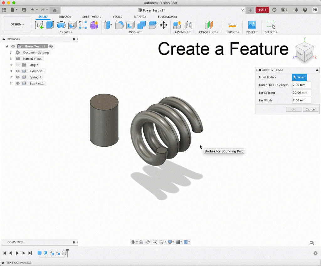
This is a long-awaited capability for the Fusion 360 API and our first iteration is now available. Please note we are considering this “Preview” functionality as there are some limitations and only some specific workflows that we support. That said this a MAJOR enhancement to the Fusion 360 API. You can now not only define a custom command dialog for your add-in, but you can actually define it as a full feature definition. This means that parametric timeline updates, model parameter changes and user edits will all now behave as expected for any other feature in Fusion 360. There is a lot of information to digest for this one, so if this interests you, check out our help documentation and learn more about this functionality.
Learn more about Create Feature Definitions
–
Improved! Using ValueInput created with createByString now sets the expression
When providing a ValueInput for the creation of anything that will result in the creation of a parameter, if the ValueInput was created with the createByString method, the expected result is the created parameter will have the expression defined by the string. This now the case.
–
[expand title=”See notable fixes”]
- Entity Tokens for Components return Occurrences
m0d0 reported on the forums that when creating an entity token for a non-root component and then binding back, an occurrence is returned instead of the component. This is fixed and now the component is returned. - Click on Help Button on command dialog not showing help on Mac
This has been addressed so your custom help documents are now properly shown on Mac computers.
[/expand]
–
If you have any questions about getting started with Fusion 360 or renewing your subscription, we’re here to help. You can purchase Fusion 360 directly from the Autodesk store. If you’d like to speak to a sales representative, please contact the corresponding number to your region:
United States: 1-833-843-3437
Canada: 1-833-843-3437
UK: +44 808 169 9659
Germany: +49 89 412 071 04
Switzerland: +41 31 539 11 46
Italy: +39 02 12 412 0560
France: +33 1 75 85 05 80
Spain: +34 93 122 5042
Poland: +48 22 15 212 44
Belgium: 3228997236
Netherlands: 31237996567
Sweden: 46313619516
Finland: 358753250819
India: +91 8010340891
Japan: 0800-080-4228
Australia: 1800 314 451
