
See the latest fixes (Jan. 31, 2022)
New Product Design Extension Now Available
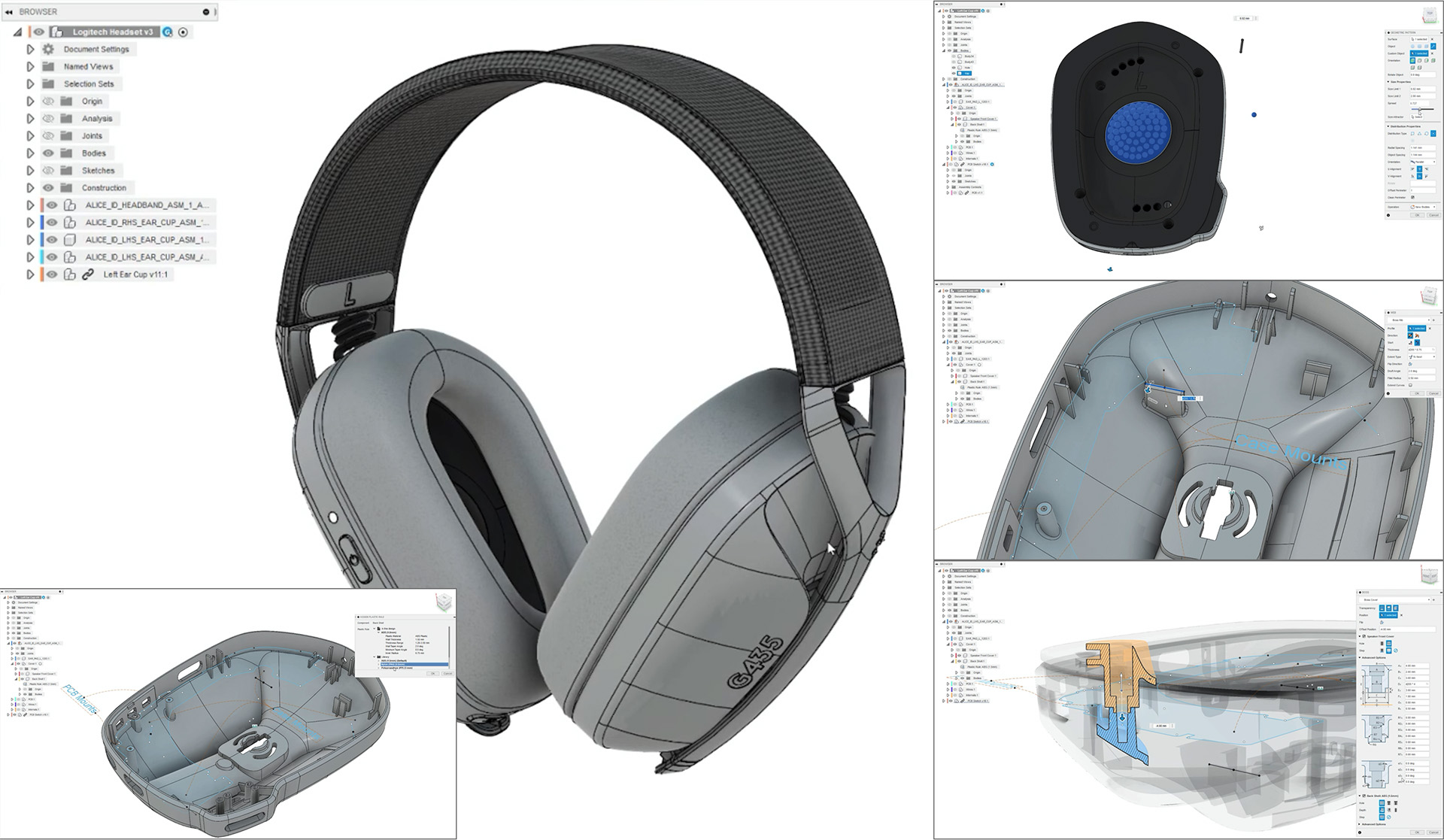
Kicking off 2022, we are introducing a brand-new extension called the Product Design Extension. Geared towards design professionals working primarily on consumer electronics and product design, the Product Design Extension gives you a set of design features that are aware of how a part is going to be manufactured, and automatically chain the workflow together, specific to the material used in the design.

When this concept is applied to plastics design, you can apply enough repeatable rules in commands like, shell, thicken, rib, boss and others and dramatically speed the time to complete because you’re spending less time typing in the same dimensions to multiple commands.
We’ve identified the next obvious command applied to newly created geometry like draft and fillet and have them automatically applied as part of the feature, driven from the material you select so that if you need to change material, the changes are instantly reflected in all the plastic features. Let’s also not forget about our new geometric pattern feature as well, making it easier for you to create the right aesthetic in your design.
As part of the launch of the Product Design Extension, we’re also excited to introduce 2 exciting new Preview Features as part of the launch: Design Advice and Volumetric Lattice. Design Advice will help you identify manufacturability concerns based on best practices for plastic injection molding and provide recommendations to address them. Volumetric Latticing enables you to create complex lattice geometry right on the solid body. If you’re interested to try these Preview Features, please refer to the Preview section of this blog post for more details.
The Product Design Extension is accessible through the Extensions button in-product.

Learn more about Product Design Extension.
Assembly Design
New Read-Only For Me option for distributed designs

When you’re working on a distributed design with multiple project members, there may be times when you want to view, analyze, or experiment with the design without reserving it and blocking access for other project members. Read-Only For Me lets you temporarily make the design read-only for yourself, so you’re free to navigate the design while other project members continue editing.
Learn more about Read-Only For Me.
New Replace Component Option
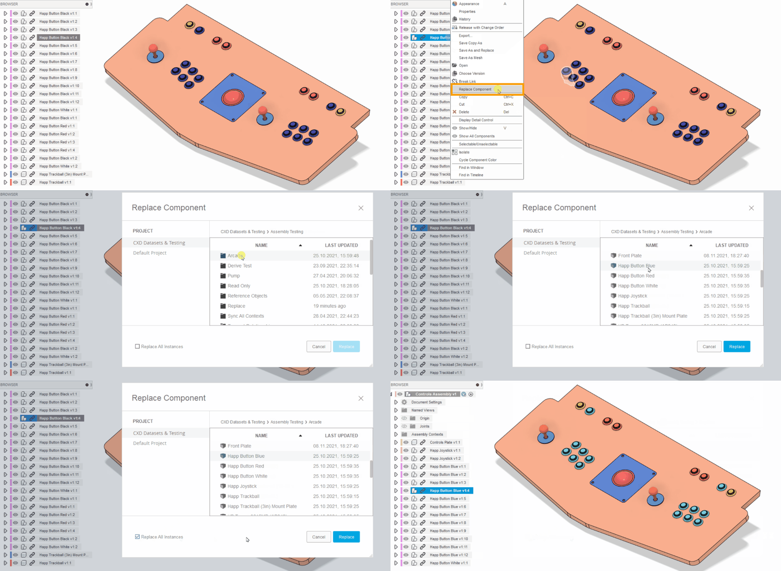
There may be times when you need to replace an external component with a different component in the context of the assembly. Previously, this involved removing all instances of the external component and inserting a new one for each instance you needed to replace. This was a manual and time-consuming process, and often required you to fix broken assembly relationships, like joints and assembly contexts.
The new Replace Component feature lets you quickly swap in a different external component at the same point in the Timeline and carry on with your work in the assembly. If the replaced component is a direct copy of the original, Fusion 360 will even reconnect those assembly relationships from the original component.
Learn how to replace external components.
Modeling
New Tangent Relationship tool
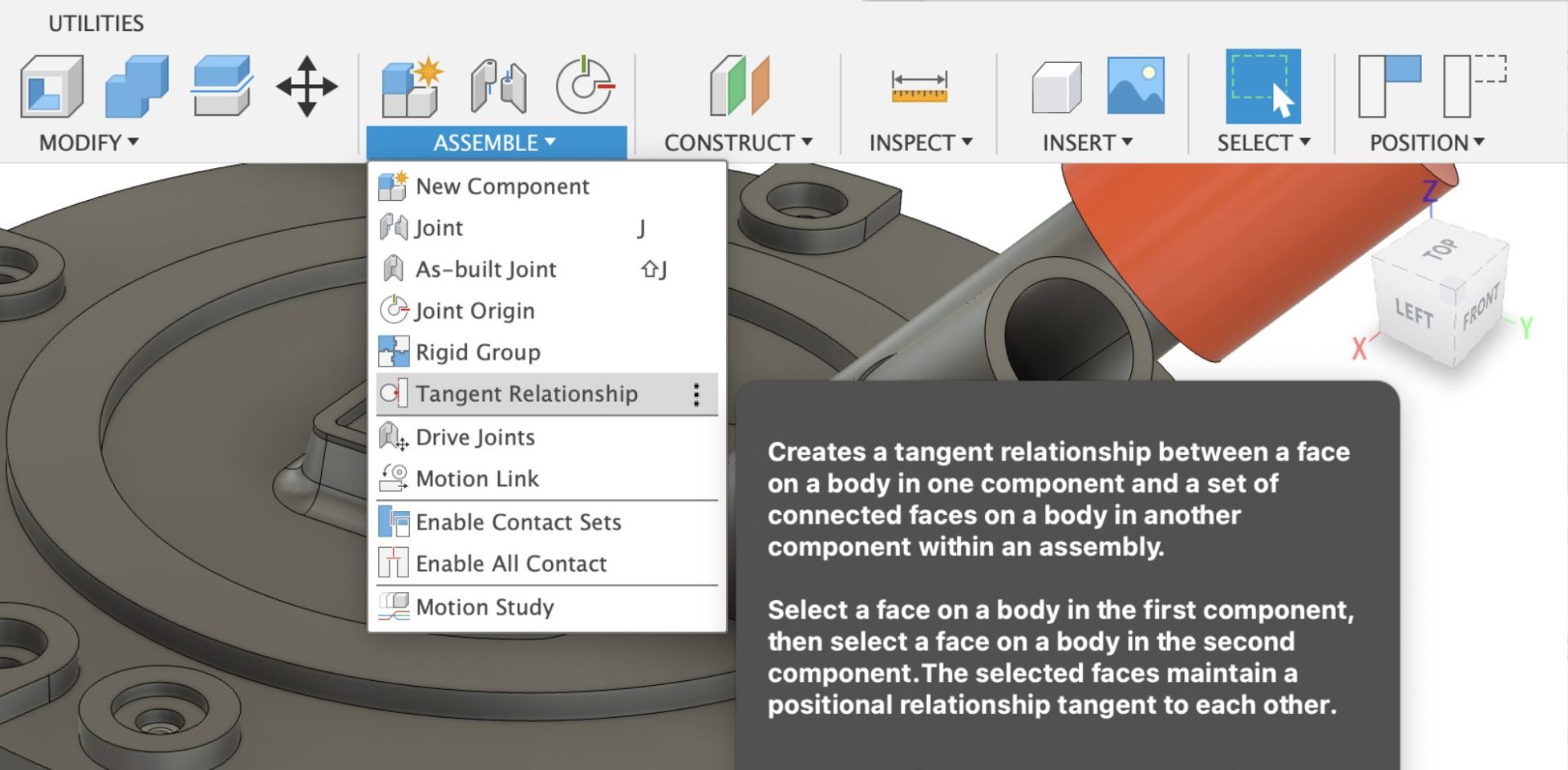
Introducing Tangent Relationship, a new command under the Assemble drop-down panel. Tangent Relationship gives you the ability to have 2 components tangent to each other and when one component moves then the other move tangentially to it.
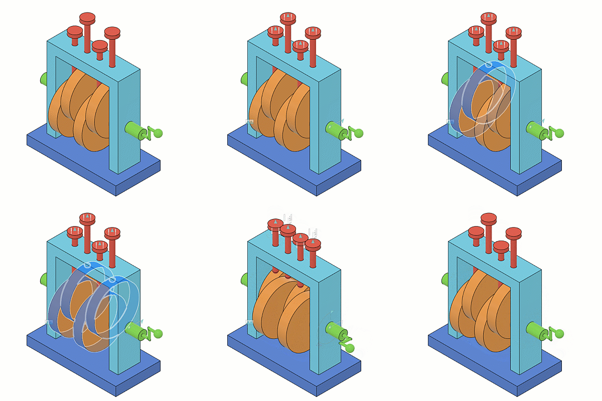
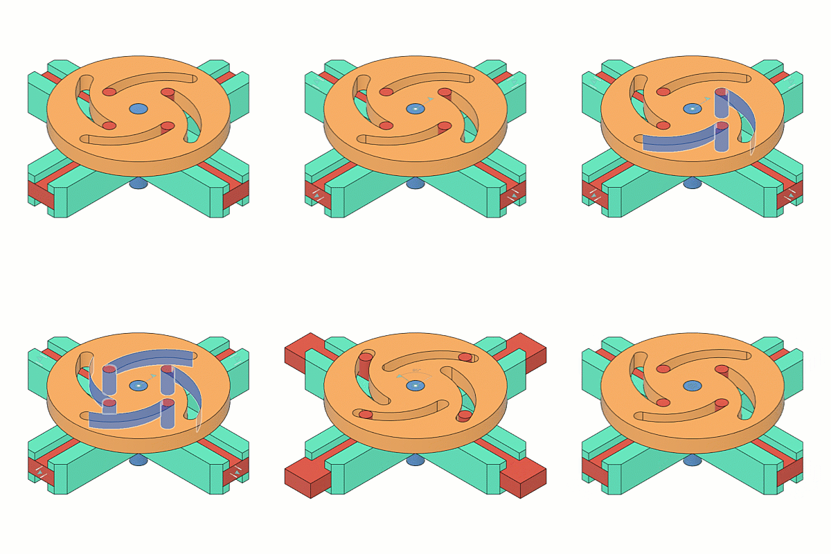
Previously, you may have tried to use Contact Sets or used a Joint limit’s rest position (if needed) to model cam in a slot / cam follower type of mechanisms. This would have revealed performance issues in complex assemblies, as the contact set algorithm used performance intensive collision detection on every drag/move. Now with Tangent Relationship tool, you’ll be able to perform those actions without the performance hit.
Once you’ve defined a Tangent Relationship, you’ll be able to edit it again in the Timeline as well as find it as an entity in the Browser under the “Relationship” folder.
Learn more about Tangent Relationship.
Reference Driven Dimensions within a sketch
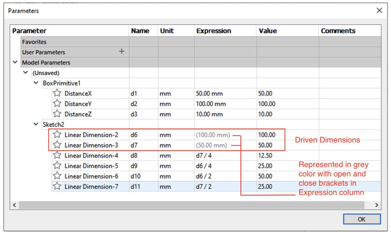
As once being one of the most voted ideas in our old IdeaStation, you are now able to reference a driven dimension within a sketch. Previously in Fusion 360, driven dimensions defined in a sketch were not exposed as parameters and therefore could not be referenced by other parameters within the same sketch, as well as outside the sketch, in other sketches. Now the are exposed as parameters, and you are able to refer them as so.
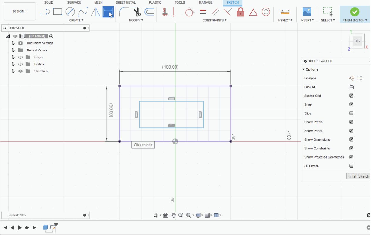
Sketch pattern distance or angle can now reference driven dimensions. All dimensions like linear, angular, axis aligned, circle diameter and radius, elliptical major/minor diameter and radius, and concentric are now also supported to refer driven dimensions (inward use) and to be used as driven dimension in other parameters (outward use) within the same sketch (with the exception being tangent and offset dimension).
We are currently working on enable you to refer driven dimensions outside of the sketch. More news around this coming soon in future updates.
Learn more about referencing Driven dimensions.
Learn how to reference Driven dimensions within a sketch.
Associative Behavior now in Create Form > Match Command
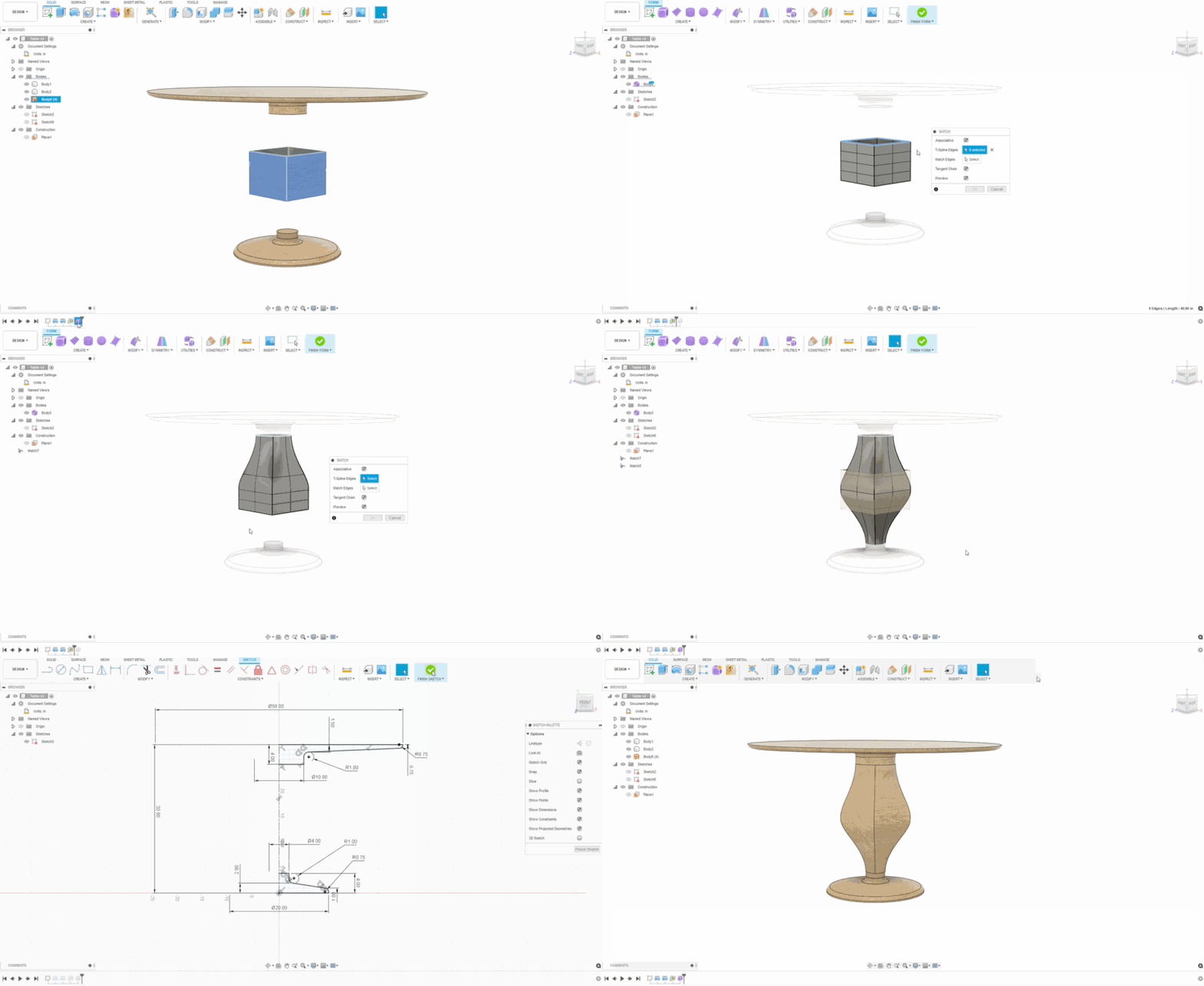
Organic modeling with associativity? Yes please! Now in the Create Form > Match command, there is a new option called Associative. Once checked, the edges matched to any reference geometry become associated with that reference geometry. This means that if at any point you decide to modify the reference geometry in the parametric design environment (albeit a solid, surface, or sketch), the T-Spline form associated to that geometry will also automatically update and maintain its relationship. This makes the hybrid use of T-Spline forms and parametric solids all the more powerful and versatile.
Learn how to create an Associative Match.
News Ways to Convert, Repair & Export Mesh Bodies
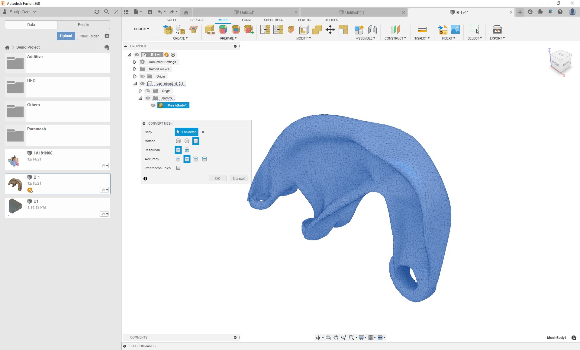
As another advantage of having the Product Design Extension comes with the new ability to convert mesh bodies into organic T-Spline bodies. That’s right – triangles faces to quad faces. It’s now finally possible.
Now in the Convert Mesh command, you’ll notice a 3rd option appear in the Method section called Organic. There are 2 things to look out for: 1. Make sure that you have the timeline enabled before you invoke the Convert Mesh tool, and 2. Make sure that the Operation option in the Convert Mesh dialog is set to Base Feature (if you are working in parametric design mode with the history Timeline turned on).*

*Please see the Improvements and fixes thread for known issues related to this functionality.
More good news – Repair Mesh has graduated out of preview and is now available as an official tool in the Mesh tab. We’ve also enhanced the Save As Mesh dialog to include an option to push the mesh object to Netfabb. If you’re exporting OBJs or 3MFs from the Save As Mesh dialog, appearances applied to mesh bodies are now also included in the exported files.
Learn how to convert mesh bodies
Learn how to repair mesh bodies
Simulation
New Fusion 360 Simulation Extension Now Available
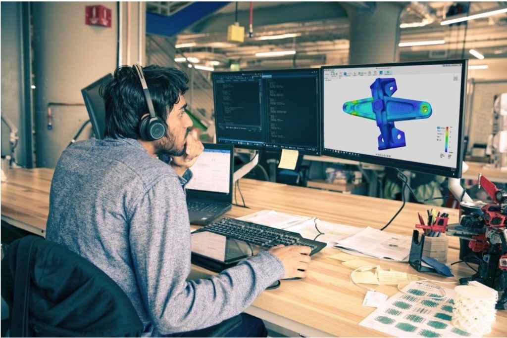
By subscribing to the Simulation Extension, you will no longer be required to pay Cloud Credits for running Simulation Studies for the duration of your Simulation Extension. The Simulation Extension has an annual and a monthly subscription option along with a 7-Days trial to evaluate your requirements. The Fusion 360 Simulation Extension unlocks key insights of product design performance and quality through mechanical, structural, and injection molding analysis tools including:
- Non-linear static stress
- Event simulation
- Modal frequencies
- Injection molding simulation (mold filling, part quality, guided results)
- Structural buckling
- Thermal steady state
- Thermal Stress Analysis
- Shape Optimization
The Simulation Extension is accessible through the Extensions button in-product.

What is the Simulation Extension
Learn more about the Simulation Extension
Injection Molding Simulation Graduates Out-of-Preview, is now available
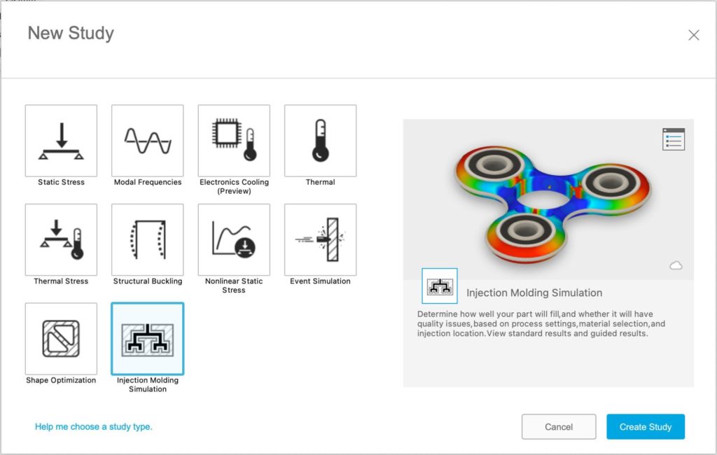
We are excited to add Injection Molding Simulation to commercially available studies in the Fusion 360 Simulation workspace. Our sincere thanks to everyone who provided us with feedback and guidance while the functionality was in preview. Following up on your suggestions, we have made improvements to the workflow as well as added new features to Injection Molding Simulation through the last few updates of Fusion 360. Kindly continue to provide your valuable feedback and suggestions, so that we can improve this technology even further.
For more information, please refer to the following links:
What is Injection Molding
How to setup Injection Molding Simulation study
Understanding Injection Molding Simulation results
Injection Molding Simulation Self-paced Learning
New self-paced learning for Simulation
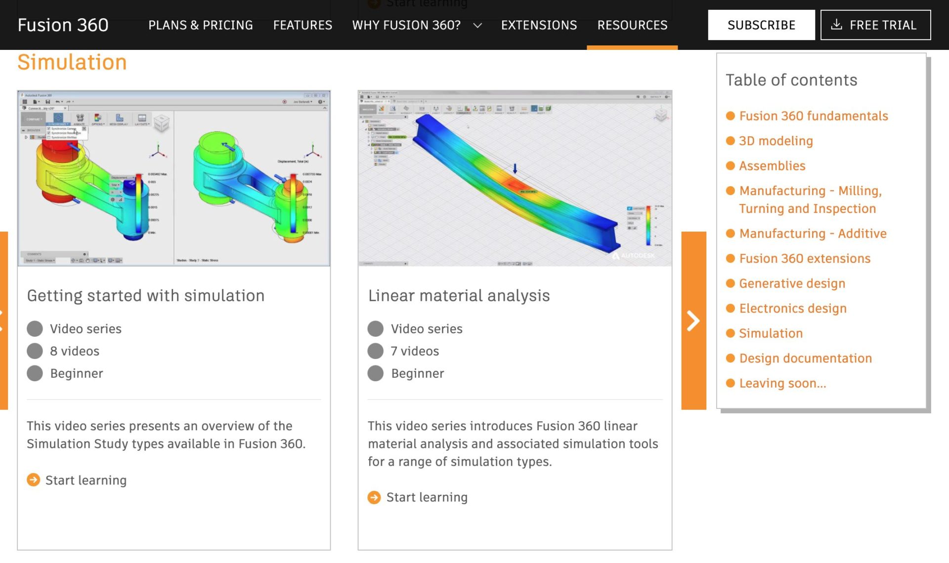
We’ve enhanced the video resources for Fusion 360’s Simulation capabilities by adding a new Getting Started with injection Molding Simulation, which introduces injection molding before showing you how to run a simulation and how to interpret the results to ensure high-quality plastic parts.
We also updated the Getting Started with Simulation video series to reflect updates to the Simulation workspace, as well as new videos about electronics cooling and injection molding studies.
Electronics
New Rotation selection option when generating 3DPCB from Sketch Profile
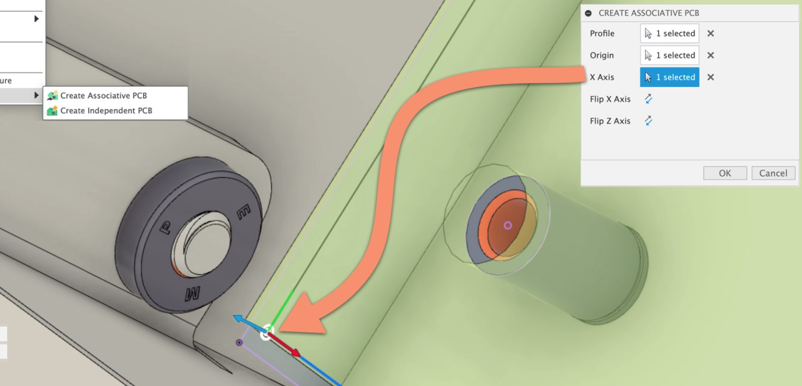
This new implementation will help synchronize the workflow between mechanical and electronic engineers. As mentioned earlier, in the Fusion 360 design workspace, you can define the PCB outline. In this update you can specify the point of origin and X axis orientation. The PCB designer will no longer wonder if the component placement is on the wrong plane.
Create PCB now called Create Associative or Independent PCB
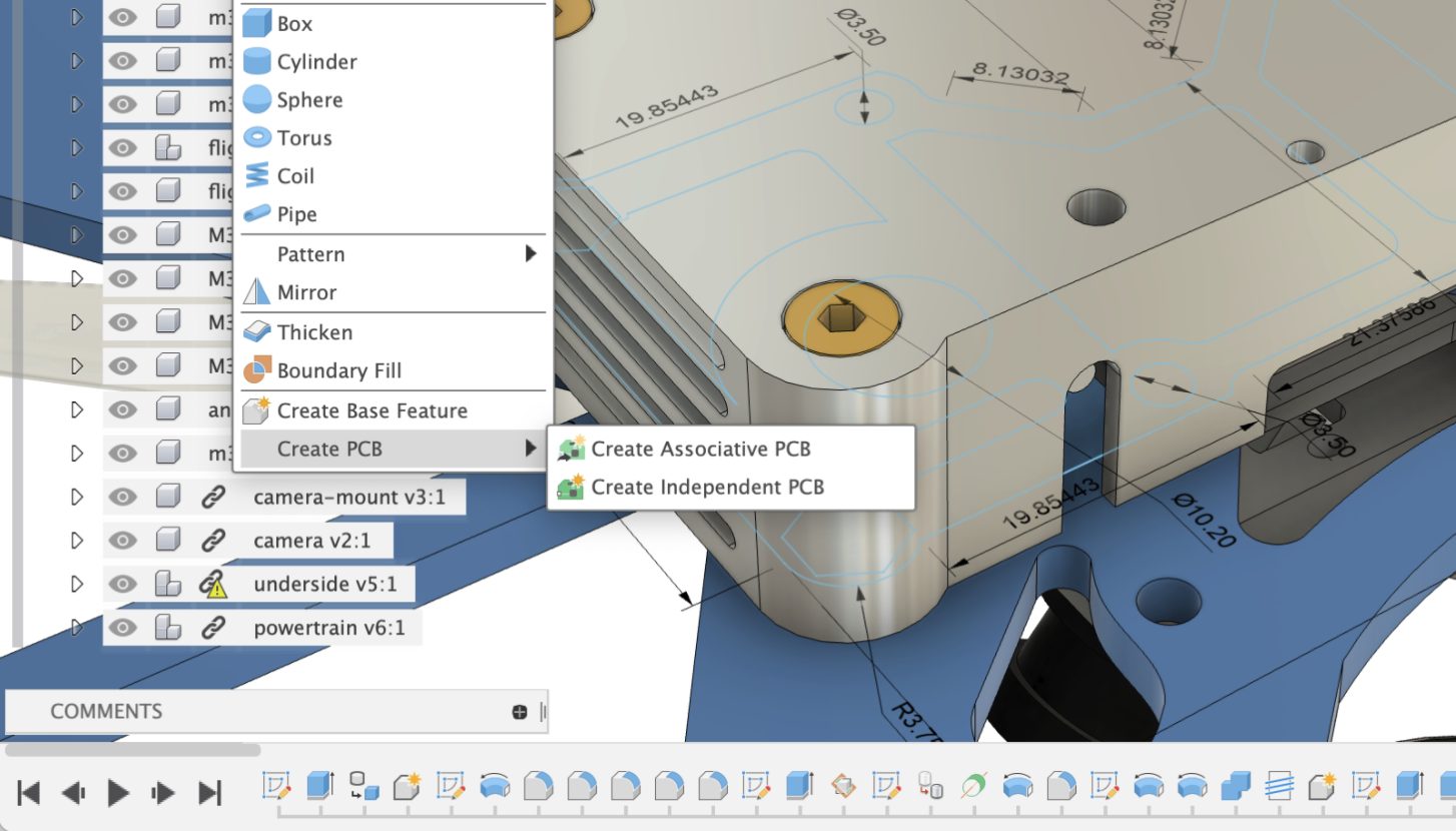
Fusion 360 is the only application that genuinely fuses the mechanical and electronic design needs into a single platform. You can project or draw your PCB circuit board outline from the design workspace. For this update, you will notice that we have renamed PCB profile capture options from “Create 3D PCB” and “Derive PCB from Sketch” commands to “Create Independent PCB” and “Create Associative PCB,” respectively. The Create Associative PCB option will provide the desired workflow of changes to the enclosure will update the PCB outline.
Export parts into library or libraries from Electronic Schematic
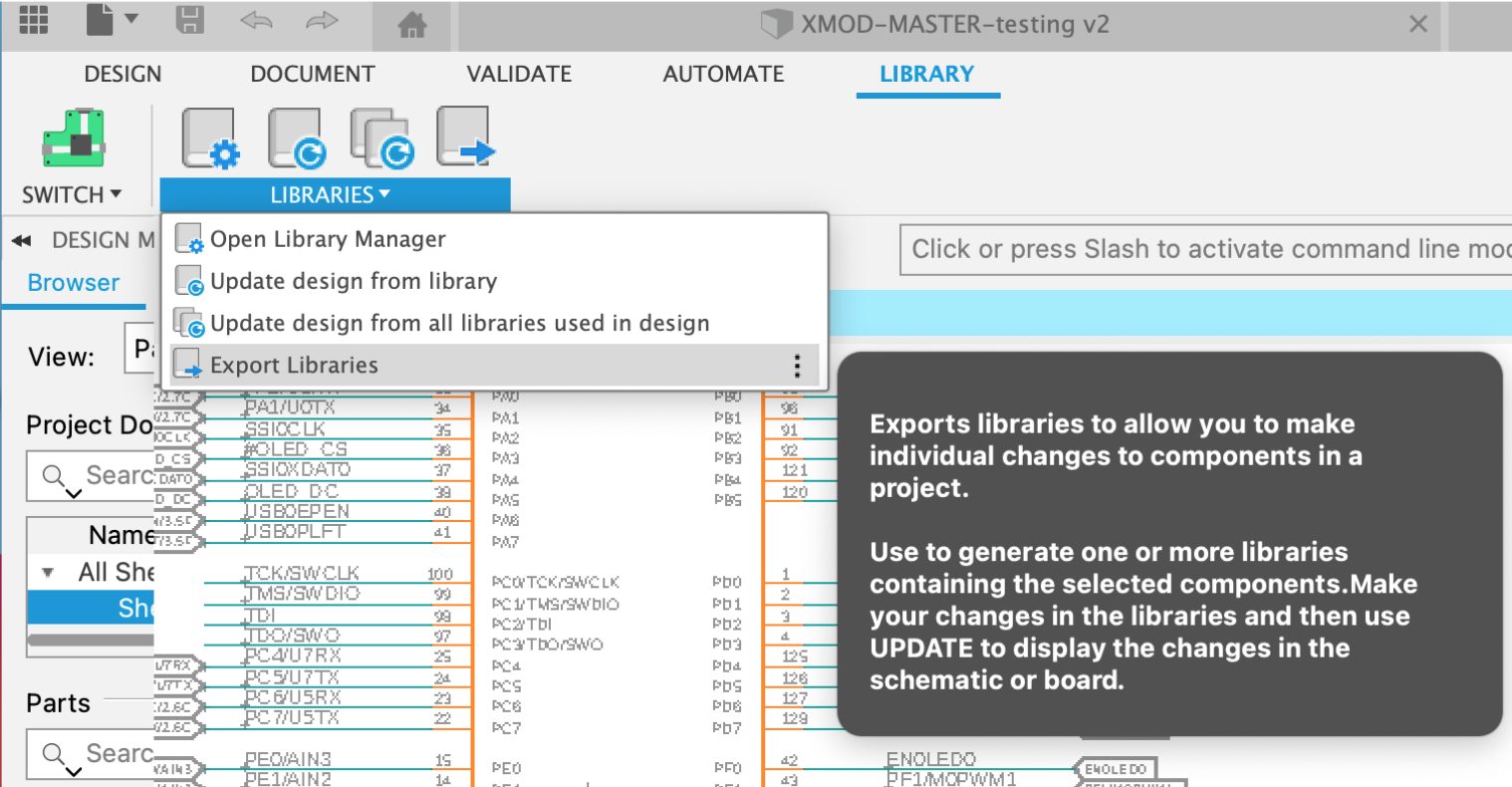
From the schematic workspace, we have now added the option to export your libraries from the loaded design from the library tab. This handy command will be beneficial for designs shared with you without the component library. You will easily export components into an existing or a new library, ready for different projects. This can be useful for exporting parts that require updating, such as mapping 3D models to your footprints. Update the design by using one of the Library Update options.
Manufacture
Toolpath Modification – Move Entry Positions (available in the Machining Extension)
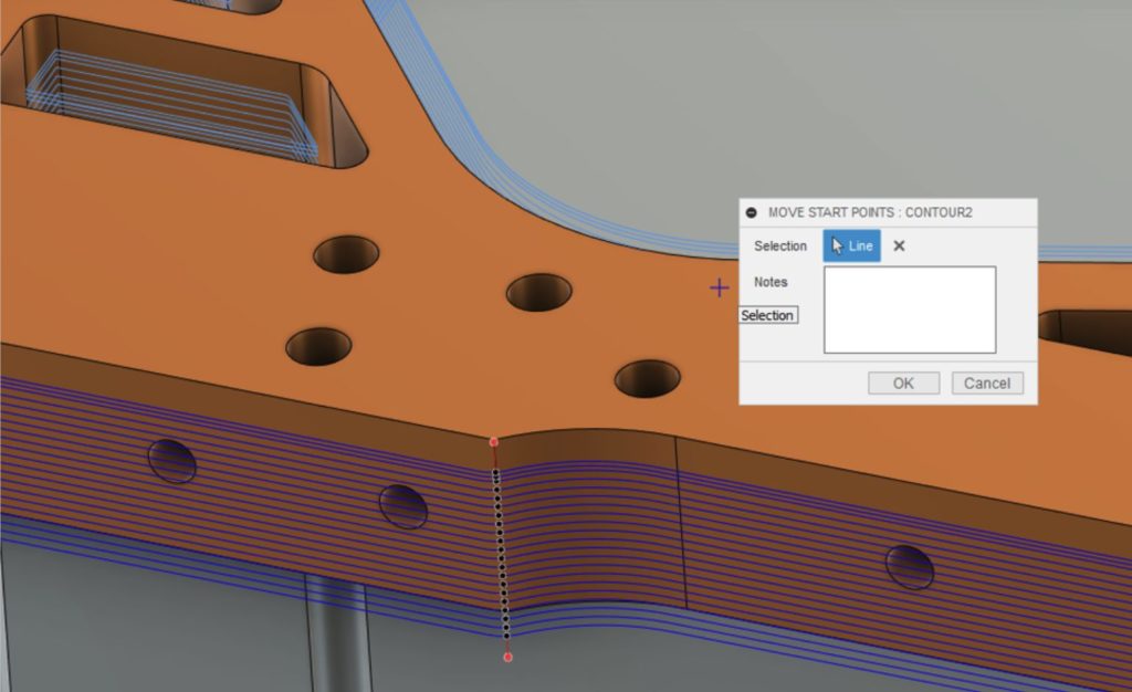
This is a new toolpath modification in the manufacturing workspace. It allows you to move the entry and exit positions of closed sections of toolpath by creating lines in space which intersect with the toolpath. This allows entry positions to be moved from ‘mission critical’ faces to avoid marks on the component and manual polishing once the component is finished. Similarly to other modifications, this event is stored in the timeline so it can be edited, deleted, etc.
The Machining Extension is accessible through the Extensions button in-product.
Learn more about Move Entry Positions
Turning – Machinable Undercuts (available in Profile Finishing)
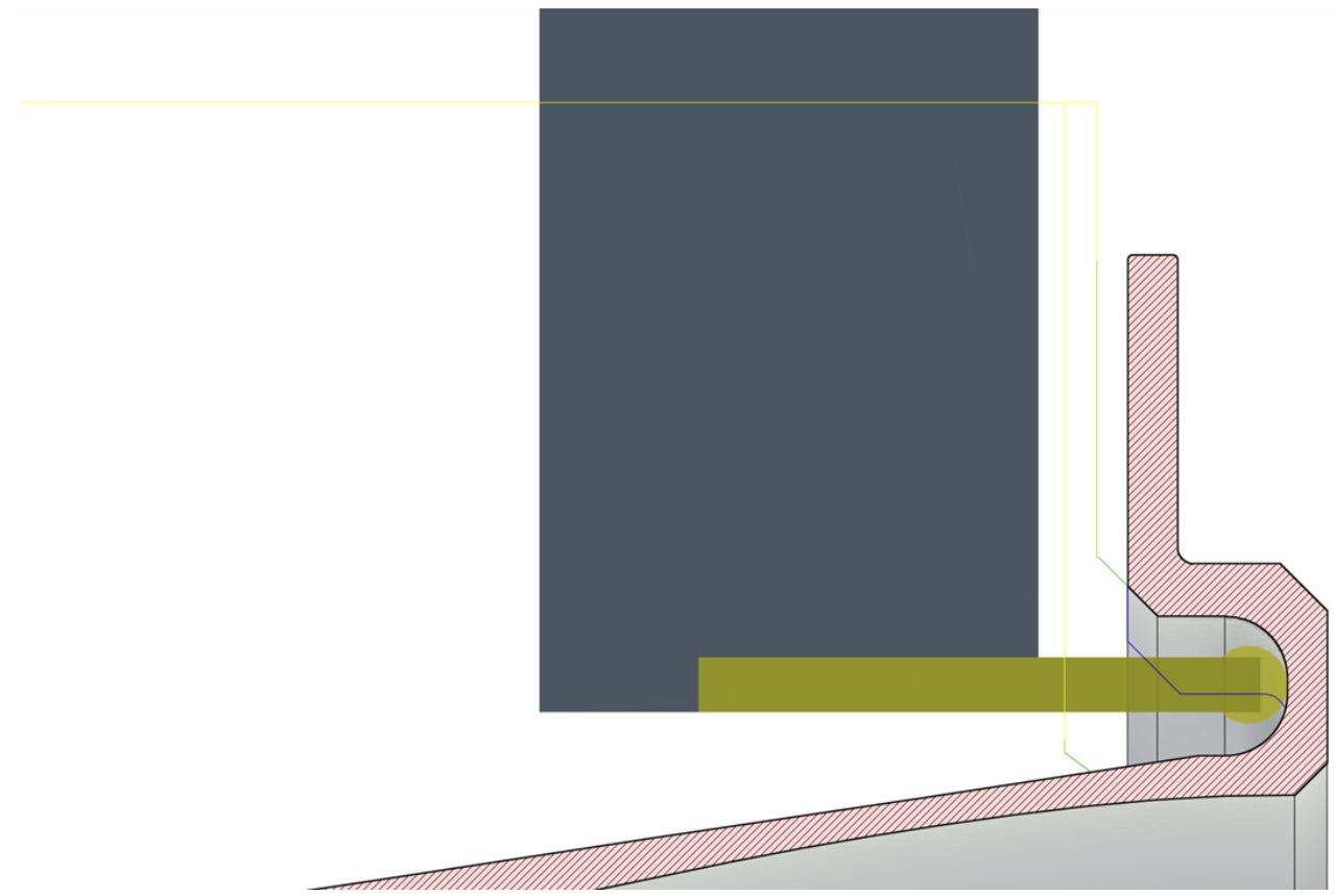
For turning workflows, you can use Grooving tools in our Profile Finishing strategy, a machining strategy that is built on our new turning toolpath algorithm. We extended the capabilities of the turning algorithm now to safely handle machining undercuts on more complex models. Previously, there would be an imaginary safety rail that would have stopped the tool from getting access to an area that was considered an undercut. This great functional enhancement is going to allow you to continue to use the model to drive your toolpaths, maintain that associative link to the design, and avoid the hassle of using sketches to generate desired toolpaths.
Turning – New Linking (available in Profile Finishing)
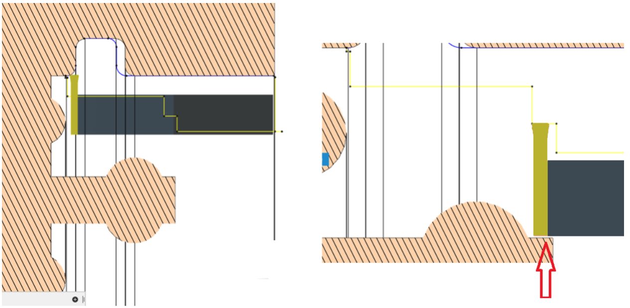
With the addition of the turning toolpath algorithm now being able to access undercut areas on models the need to safely move in and out of those areas was paramount. In this update alongside Machinable Undercuts we enhanced the linking moves for turning toolpaths. There are a lot of details to the new linking and a blog will be published soon for all the details.
Material Grain Control (available in the Nesting & Fabrication Extension)
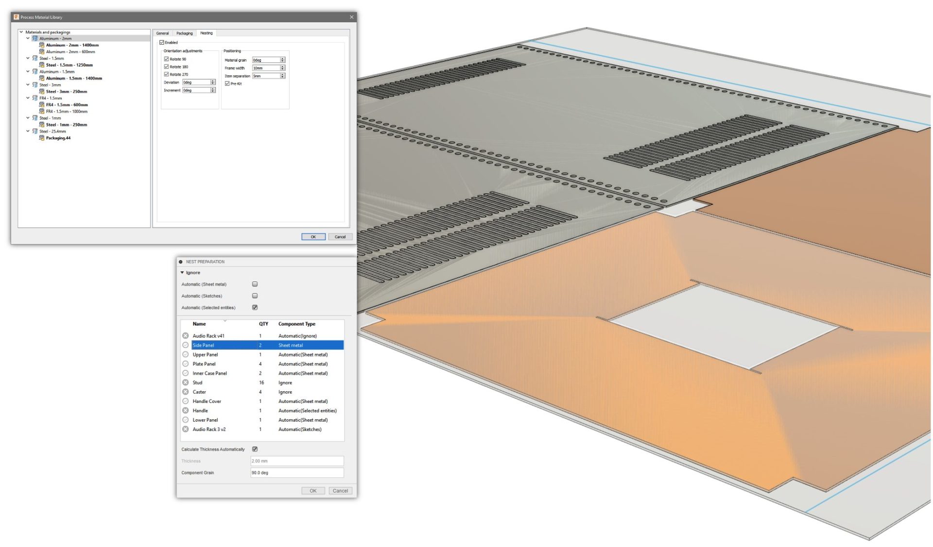
In the Nesting & Fabrication extension, you’re now able to control material grain in this release. Every material has a grain, but this is especially important for anyone working with wood, as it allows you to aesthetically align your parts. Simply set the component and sheet grain directions and watch the Nest Studies take care of the rest. Don’t forget, the Nesting & Fabrication Extension is associative, so any adjustments to component or material grain are consumed by the nests, minimizing any rework.
The Nesting & Fabrication Extension is accessible through the Extensions button in-product.
Learn more about Nesting & Fabrication Extension
Part Labelling (available in the Nesting & Fabrication Extension)
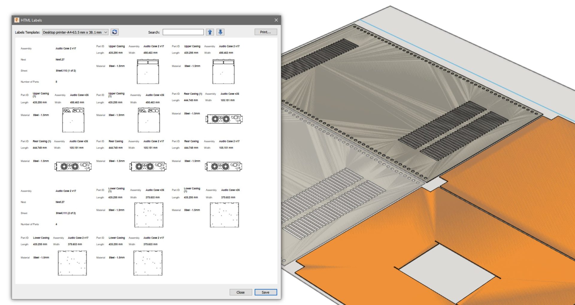
Keeping track of your parts as they are manufacturing is something we often take for granted. With this release of Fusion 360 and the Nesting & Fabrication Extension, we are introducing the capability to create customizable and printable labels to improve part tracking. Several templates are included by default to get you up and running, including common label paper and label printer sizes.
The Nesting & Fabrication Extension is accessible through the Extensions button in-product.
New self-paced learning for Manufacturing
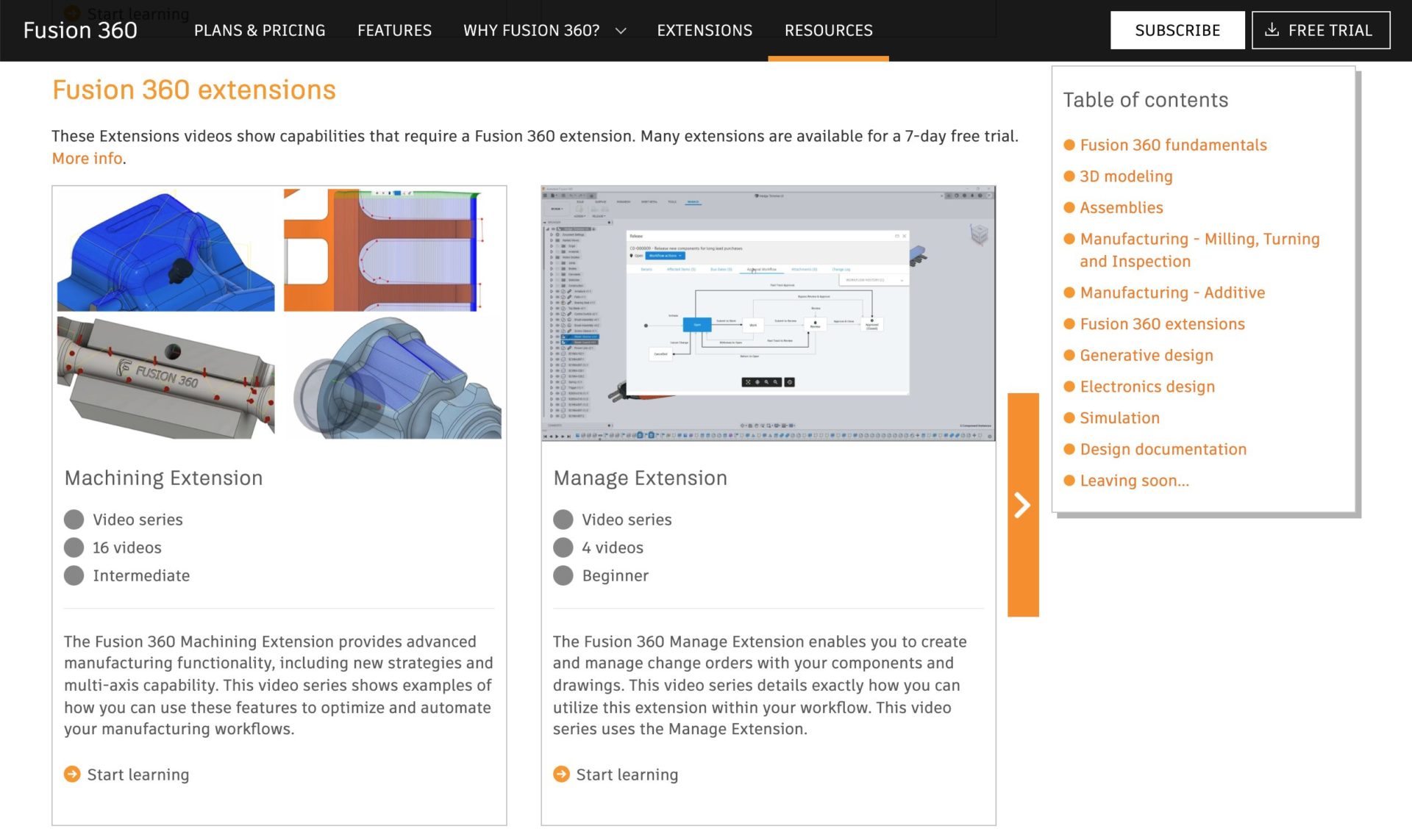
We’re continuing to expand the video resources available for Fusion 360’s Manufacturing capabilities with new videos in the Machining Extension video series introduce the 5-axis options available for the Steep and Shallow strategy. The videos show different tool-axis options and highlight scenarios where these options help produce a safer, more efficient, toolpath.
We also added a new Inspection video series shows how to use probing on a CNC machine tool for part setting and how to use probing to inspect that manufactured parts are within tolerances. Fusion 360 supports several device types for inspecting parts, including CNC machines and manual inspection instruments like calipers.
Additive
SLS Selective Laser Sintering with the Formlabs Fuse 1
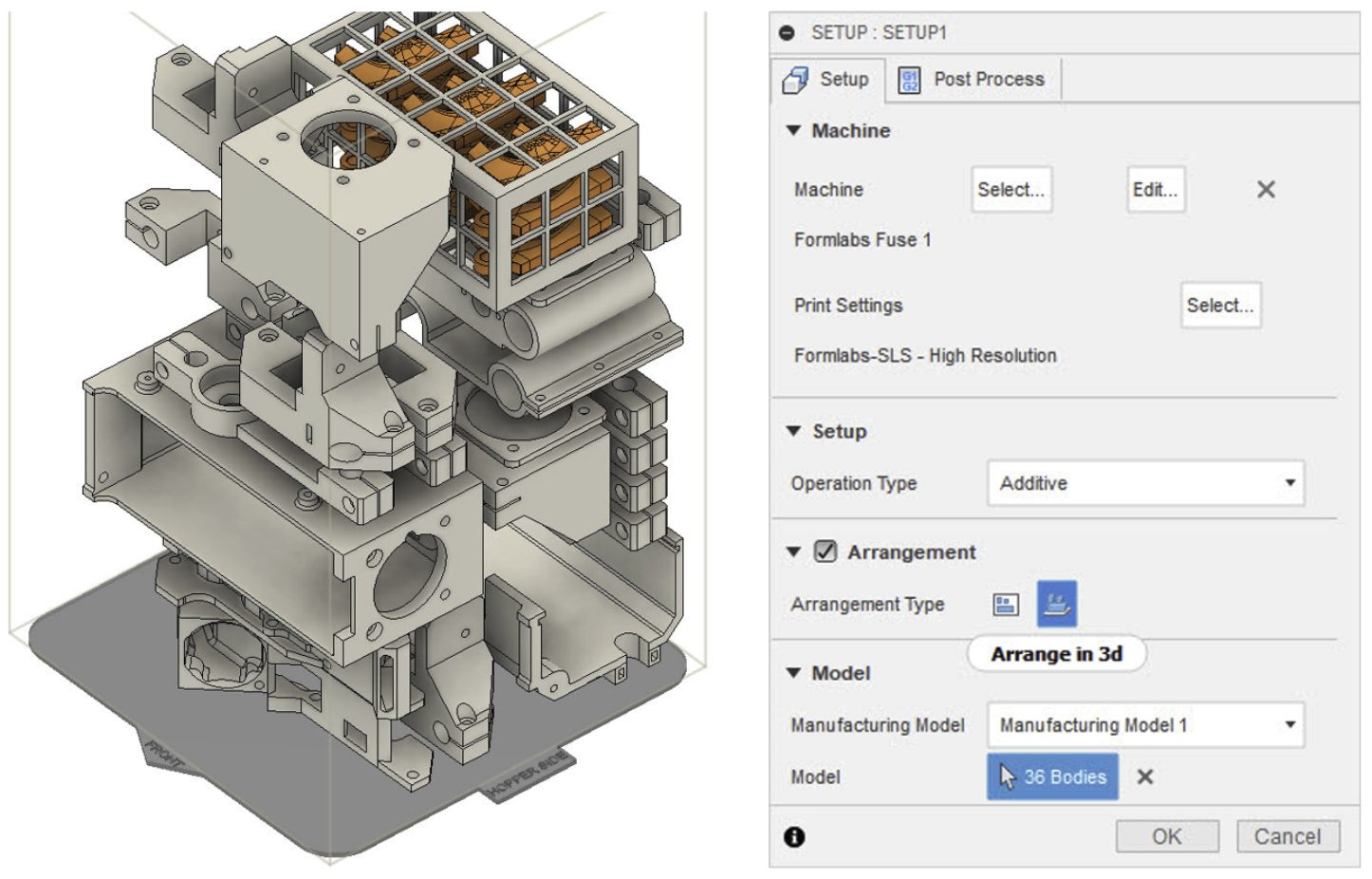
We are continuing to expand the list of 3D printing technologies we support, and we’re excited to introduce the ability to prepare your 3D prints for the Selective Laser Sintering (SLS).
The first SLS 3D printer we are supporting is the Formlabs Fuse 1. Just like all the other additive workflows in Fusion 360, you are now able to prepare the print by selecting Formlabs Fuse 1 as the machine to use in your Additive Setup. When you click the Setup command from the additive tab, you will notice that a new Manufacturing Model is now automatically created if one does not already exist and used for the Additive Setup. This will ensure that any automatic or manual part arrangement impacts the active manufacturing model and not the root model. In the Setup dialog, you will notice that you can now select “Arrange in 3D” as a new Arrangement Type for SLS and MJF printers. When you click OK, this option will quickly pack your parts within the build volume of the SLS/MJF printer, based on their current orientation and the outbox dimensions of the selected components.
When you are done arranging your parts, simply export the active setup as a “*.form” file and open it within Formlabs PreForm software.
Tip: Make sure that you have selected Fuse 1 as your printer type within PreFrom before opening the *.form file you exported from Fusion 360 to print your models with this printer.
See more Support Structure Improvements for FFF, SLA ,and SLM Machine
Learn how to prepare parts for additive manufacture
eMotion Tech and LulzBot 3D printer support added
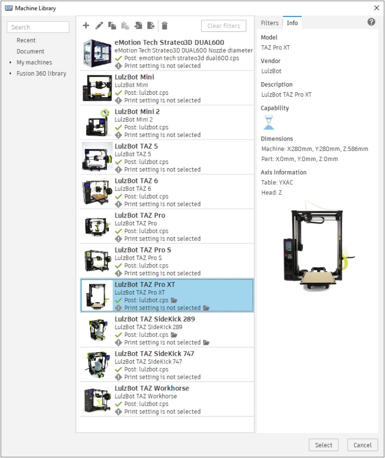
The Machine Library now includes several new LulzBot (Mini, Mini 2, TAZ 6, TAZ Pro, TAZ Pro S, TAZ Pro XT, TAZ Workhorse, TAZ SideKick 289, TAZ SideKick 747 and TAZ 5) and eMotion Tech (Strateo Dual 600) FFF printers. The Post Library also has a post associated with these printers, so you can setup the prints and generate G-Code for your machines.
Consolidated Print Settings in Additive Tab

We have simplified the print setting selection/edit workflow to remove duplicated steps and streamline the process. Now, print setting selection will only happen from the setup dialog. Note, this is also the case with the machine. To learn more, check out this forum post.
Notice: Print Settings, Infill, and Support Panels no longer showing in toolbar
New Previews
Resolve External Components (Public Preview)


If you’ve ever tried to open a design in Fusion 360, but couldn’t because it contains missing external components, this preview feature is for you. The new Resolve External Components preview lets you open assemblies with unresolved external components and attempt to resolve them. After you enable the preview, if you try to open a design with unresolved external components, you’ll see a notification and then you can open it. In the Browser, right-click an unresolved component, then select Resolve Component or Delete.
The 2 primary reasons a design would go miss are Archive/Deletion and Permissions. Resolutions vary based on the reason an external component is unresolved: Unarchive a project , Request access / restore, or permissions Delete.
If a design is missing because it’s deleted, it will be missing for everyone. However, it’s important to note that if a design is missing because you don’t have access to the project where it’s located, it may be available for other project members. In this case, we recommend that you work to gain access to resolve external components before you make any significant changes to the design.
If you really do need to make any significant changes to a design in this state before you resolve the components, you’ll need to use the new Modify > Compute Unresolved command first, which will compute only the features related to unresolved external components in the assembly. You can run Compute Unresolved manually to see the outcome or Fusion 360 will automatically invoke it when you first edit the design to ensure you are working on the latest computed state.
We recommend that you resolve missing components as soon as you encounter them.They are not expected to be maintained over the long term and you should address them as general design maintenance.
Learn how to resolve external components in an assembly.
Design Advice (Preview for Product Design Extension)

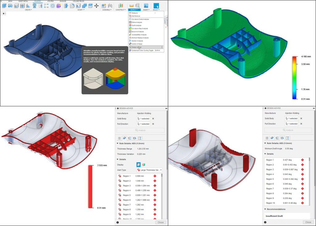
As a cornerstone of the Product Design Extension offering, we want to give you tools that are manufacturing aware and that can provide smart recommendations to improve the performance of your design and help you make better decisions. This is what Design Advice is all about, and it is now available to try for free as a Preview Feature (with a Product Design Extension subscription).
Once enabled, you’ll be able to access the feature under the Inspect Panel. Once activated, you’ll have 4 selectable advisory sections: Thickness, Undercuts, Drafts, and Knife-Edges. These elements all play an important role in how well your part will be injection molded. Based the material of your part and how your part was designed, Design Advice will give you manufacturability warnings and suggestions for fixes, as well as rule details for further analysis. This is some powerful stuff, and we can’t wait to hear about what you think of it.
Volumetric Lattice (Preview for Product Design Extension)

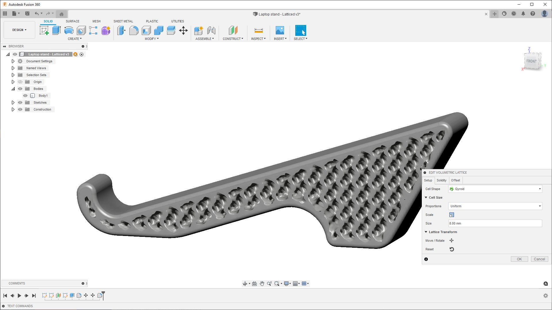
What if you could create complex volumetric lattices within your design, just like how your 3D printing utility does it? With the new Volumetric Lattice Preview functionality now available to try as part of the Product Design Extension, you can do exactly that. Once enabled in the Preview Features section (and with a Product Design Extension subscription), you’ll find the tool under the Solid Tab > Modify Panel. Choose between Cell Shapes like Gyroid, Cross, and Schwarz P. You can also adjust the Proportions, Scale, Solidity, as well as Offset options. Once you’re all set, right-clicking on the body will reveal Volumetric Lattice Actions, such as Show/Hide, Create Mesh, and Delete. Since this is still a Preview Feature, we’re looking for your feedback, so feel free to let us know what you think.
Learn how to modify volumetric properties of a solid body
Additive Process Simulation Preview (Available for the Additive Simulation Extension)
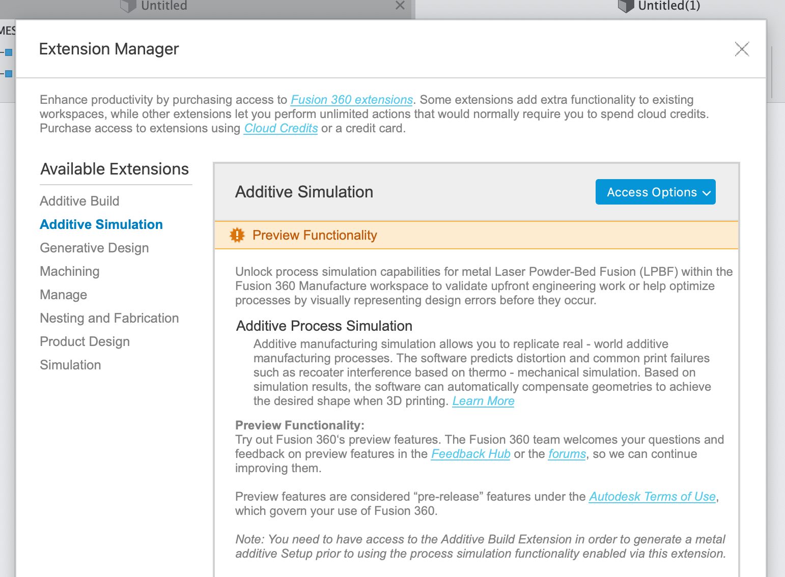
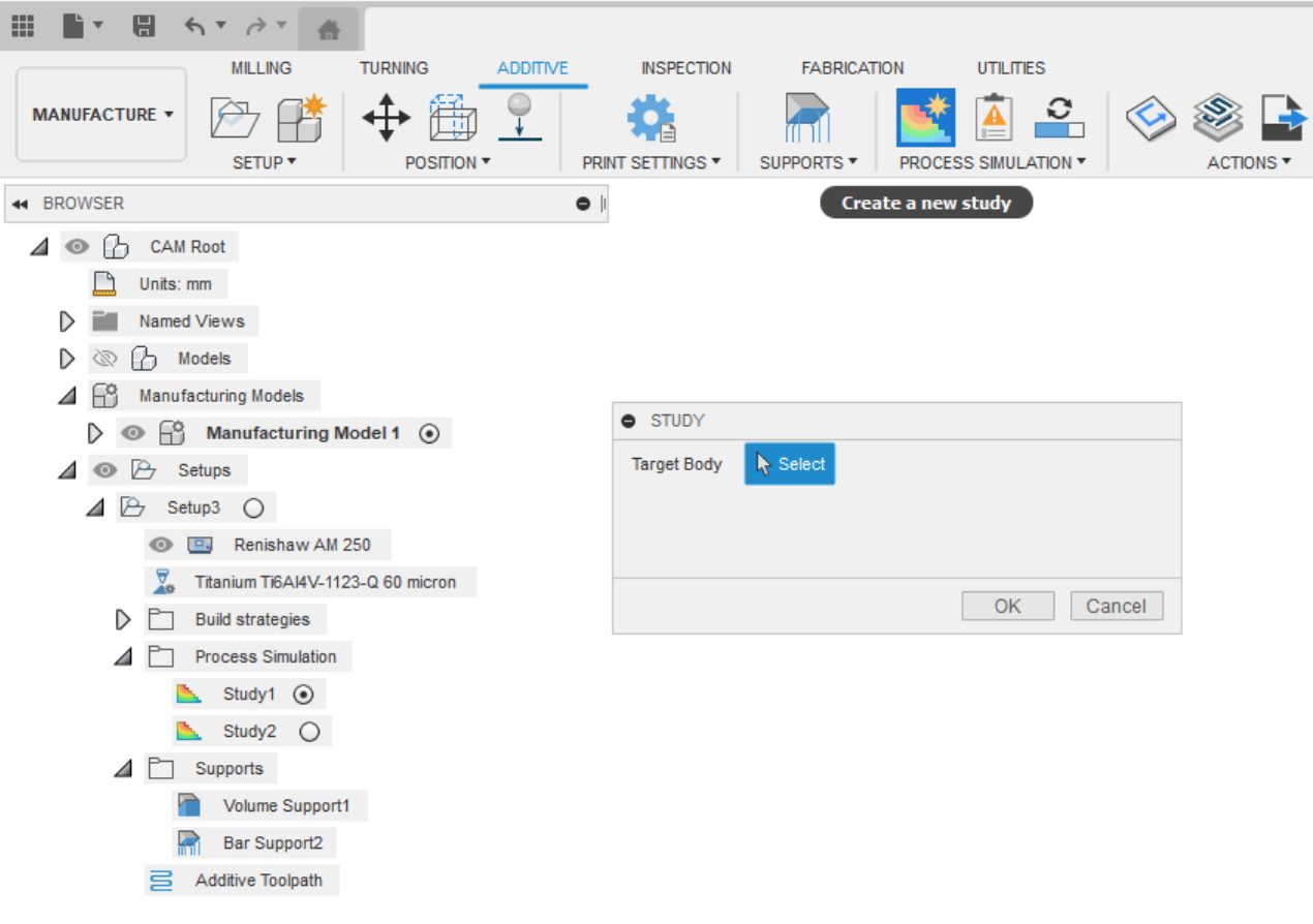
With the January 2022, update you can now create multiple Additive Process Simulations within the same Fusion 360 design. Simply select the Create a new study button in the Additive tab, Process simulation panel and choose a target body you wish to simulate. Go through the pre-check steps to adjust your Process Simulation options if necessary, and you are ready to simulate the metal Laser Powder-bed Fusion (LPBF) process for common failure modes such as Displacement and Recoater blade Clearance and export a Compensated model to minimize calculated distortions.
The Additive Simulation Extension is accessible through the Extensions button in-product.
API
Important Notice: Python Version Update Coming

This is a “good news and bad news” kind of warning. The good news is the version of Python being used in Fusion 360 will be updated in the next Fusion 360 release to Python 3.9.7. That’s great news because the Python language continues to be enhanced, and we all want to use the newest features.
The bad part of this announcement is that if you write or use any Python apps delivered as .pyc files, this change will break them. They’ll be broken because .pyc files are tied to the version of Python used to create them. Add-ins compiled with the current version (3.7) will not be compatible with the next release (3.9) and will fail to load. This change does not affect any add-ins where the .py source code is available.
We’re currently working with the Autodesk App Store team to determine the impact of this change and develop a plan to minimize the impact on you and our customers. Watch the Fusion 360 API and Scripts forum for a sticky post that will contain the details once we’ve decided on the best solution.
Learn more about what’s new, improved, and fixed in API
Improvements & Fixes
To learn more about other improvements that went into this update, our extended list of fixes to issues reported by you, as well as known issues, check out the related Known Issues, Improvements and Fixes forum thread below.
See improvements and fixes for this update