
v.2.0.8609
Important Notice: Windows 7 Compatibility
As we continue to develop Fusion 360, not only are we improving existing functionality as well as implementing new features into the software, we’re also maintaining support for a number of different operating system versions (for macOS as well as Windows). This means testing for bugs, developing fixes for them, as well as releasing important updates.
Back in January 2020, we announced that we are ending Windows 7 support. For those of you still running Windows 7, you can still run Fusion 360 but we will no longer be supporting it with testing and fixes. We recommend that you upgrade to a new version of Windows to get the most out of Fusion 360. Check out the Microsoft Windows 7 page for things you can do.
Improved! Select Project Type in Fusion Team

Previously if you were working in Fusion Team on the web and created a new project, the project type would always default to Closed. We learned that many of you didn’t even know that there were different project types to choose from, and we realized that changing the project type was undiscoverable. Now when you create a new project in Fusion Team, you’ll have the option to select the appropriate Project Type for your new project.
[icon name=”wrench” class=”” unprefixed_class=””] [expand title=”Issues Fixed – Click to expand”]
- We found a few areas in the tool library that could use some minor tweaks, so we made it more resilient and more stable.
- We fixed an issue with the Manufacture Tool Library where it appeared entirely off-screen where you couldn’t interact with it. Apparently there was a glitch with the UI engine and it was acting funny. This is now working as it should.
- Apparently the Clear all filters button wasn’t doing it’s job correctly when you wanted to clear your search filter in the tool library. It wasn’t actually clearing the search bar. Our bad- now it does.
- We heard that a bunch of you have been experiencing instability while sketching. While we didn’t have any steps to reproduce what you were seeing, we dug into it and discovered some code that was messy. We quickly gave it a make-over and now we’re back in business with sketching in tip-top shape.
- Joints and As-built Joints were experiencing some unhealthy grinding of the gears, so we hit it with some WD-40 and now you should no longer be seeing any crashes while using them.
- There was a bug in the Electronics library > Create New Package workflow where selecting the “Chip Array 2 Side Convex” package (in the package generator), and modifying the pin value to 4 incorrectly generated a terminal, which overlapped with the pins. Now when you do this, the preview and resulting package are correctly generated.
- We fixed an issue where undoing consecutive “Dissolve” actions committed in the browser in direct modeling caused Fusion 360 to become unstable.
[/expand]
v.2.0.8560
[toc]
Usability
[icon name=”star” class=”” unprefixed_class=””] New! Profile name is now your avatar or initials
Your profile access point is located in the top-right corner of Fusion 360

Some of you with eagle-eyes will notice that we’ve updated how your profile name is displayed. Previously you’ll see your first name and last name in the top-right corner of Fusion 360. We’ve updated this to show your profile picture (if you’ve uploaded one previously) or your first and last name initials. If you hover over your avatar, it’ll display your full name. This is one step closer to a more consistent experience between Fusion Team and Fusion 360.
[icon name=”star” class=”” unprefixed_class=””] New! Fusion 360 now available in Italian and French
Profile > Preferences > General > User language

A few of you got a little sneak peek at this in the last update, but now it’s official – Fusion 360 is now available in French and Italian. You can select the language you want to run in by going to the Your Profile avatar > Preferences > General, and select the appropriate language under User language. Restart Fusion 360 and it should be in the language you’ve picked.
[icon name=”info-circle” class=”” unprefixed_class=””] [expand title=”See examples”]


[/expand]
[icon name=”wrench” class=”” unprefixed_class=””] [expand title=”Issues Fixed – Click to expand”]
- We received reports from some of you stating that pressing the Tab key or selecting by size while the Draft Analysis command was active caused Fusion 360 to lock up. This definitely shouldn’t happen, and now it won’t happen again.
- We fixed an issue where the data panel was scaling incorrectly for some of you, making it incredibly frustrating to navigate and use. It had to do with some legacy code not playing well with recent code changes. This issue is now fixed.
- If you close Fusion 360 with pending uploads, you’ll see a reminder that you’ve got data still being uploaded, and that you can cancel or quit. What became annoying was that this dialog appeared on top of all the other windows you have open. Thanks Vmenonsandeep for the heads up!
- Mah6786 reported an issue where Fusion 360 became unstable when Save Copy As was used to save as or export the design into another project folder. We took a look at the code and while debugging it we found that the Save Copy As functionality was making wonky calls. We told it to stop and now it’s working fine.
- When working with multiple monitors, especially if you have your screens stacked one on top of each other, accessing the workspace switcher will pop the menu open upward (if you have Fusion 360 running on the bottom screen), making it difficult to see all the workspaces. Now the menu always drops downward.
[/expand]
Sketching & Modeling
[icon name=”star” class=”” unprefixed_class=””] New! Edit-in-Place now out-of-preview
When hovering over an inserted referenced part in the browser, click on the Edit in Place icon
Back in March of 2020, we announced that Edit-in-Place was going to be available to try in Fusion 360 as preview functionality. After listening to your feedback, refining the experience, and ironing out the kinks, we’re glad to report that Edit-in-Place is now officially out of preview and available for you to use in your design workflows.

Edit-in-Place enables you to make changes to a reference design that was inserted into a larger assembly design in-place, and in context to the whole assembly. Since the inserted reference design is linked to the original design, previously you had to open it as a separate document to make changes to it. Now you can make edits to it exactly where it was inserted in the overall assembly.
[icon name=”info-circle” class=”” unprefixed_class=””] [expand title=”Learn more”]
- You can now insert reference designs during Edit-in-Place
While Edit in Place is active, right-click on a design in the data panel and select insert into current design
This gives you more flexibility to build your assembly designs, and removes unnecessary road-blocks and wonky work-arounds to get the job done.
- Edit-in-Place now also works in direct modeling
You can work in direct modeling by turning off the timeline
Create Basefeature will also create a direct modeling “sandbox” within a timeline-enabled design.
Direct modeling workflows do not capture any history in the timeline, and changes made are direct and non-parametric. There are situations where direct modeling is very beneficial, like making a quick change to a specific part that doesn’t need to be captured historically. Now you can edit an inserted design without capturing any history.
To learn more about how Edit in Place can help you accelerate your design workflow, check out our blog post, help documentation, or this tutorial video created by fellow Fusion 360 user/YouTuber John Hackney.
[/expand]
Edit-in-Place Help Documentation
[icon name=”star” class=”” unprefixed_class=””] New! Parting Line Mode in Draft Command
Design workspace > Solid Tab > Modify Panel > Draft > Parting Line Mode

Being able to create a parting line for plastic injection molding is one the fundamental aspects of designing a product for manufacturability. Now in the Draft command, you’ll finally be able to create a parting line by using the Parting Line Mode.
[icon name=”info-circle” class=”” unprefixed_class=””] [expand title=”Learn more”]

Technically speaking, a parting line is the dividing line that splits the core and cavity halves of a molded shell/housing, and is where the draft angle changes.

This mode will now make it easier for you to create that parting line in your design, using the line as a splitting tool for the Split Body command, and end up with a proper parting line.
[/expand]
Parting Line Draft Help Documentation
[icon name=”star” class=”” unprefixed_class=””] New! Ruled Surface Command
Design Workspace > Surface Tab > Create Panel > Ruled

Another very welcomed addition to the Surface creation toolset is the Ruled surface command. Now you’re able to select/chain select surface edges, pick between normal, tangent, or direction types, define the distance, angle, and create new surfaces based on those rules. It’s as simple as that.
[icon name=”info-circle” class=”” unprefixed_class=””] [expand title=”See it in action”]
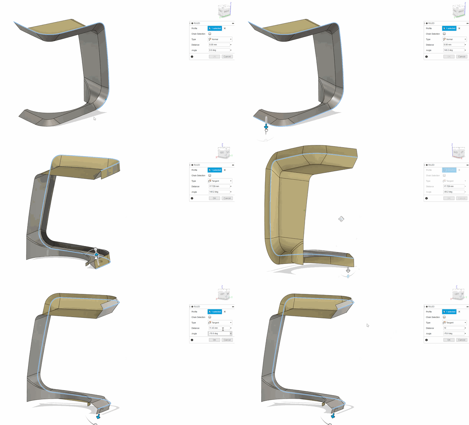
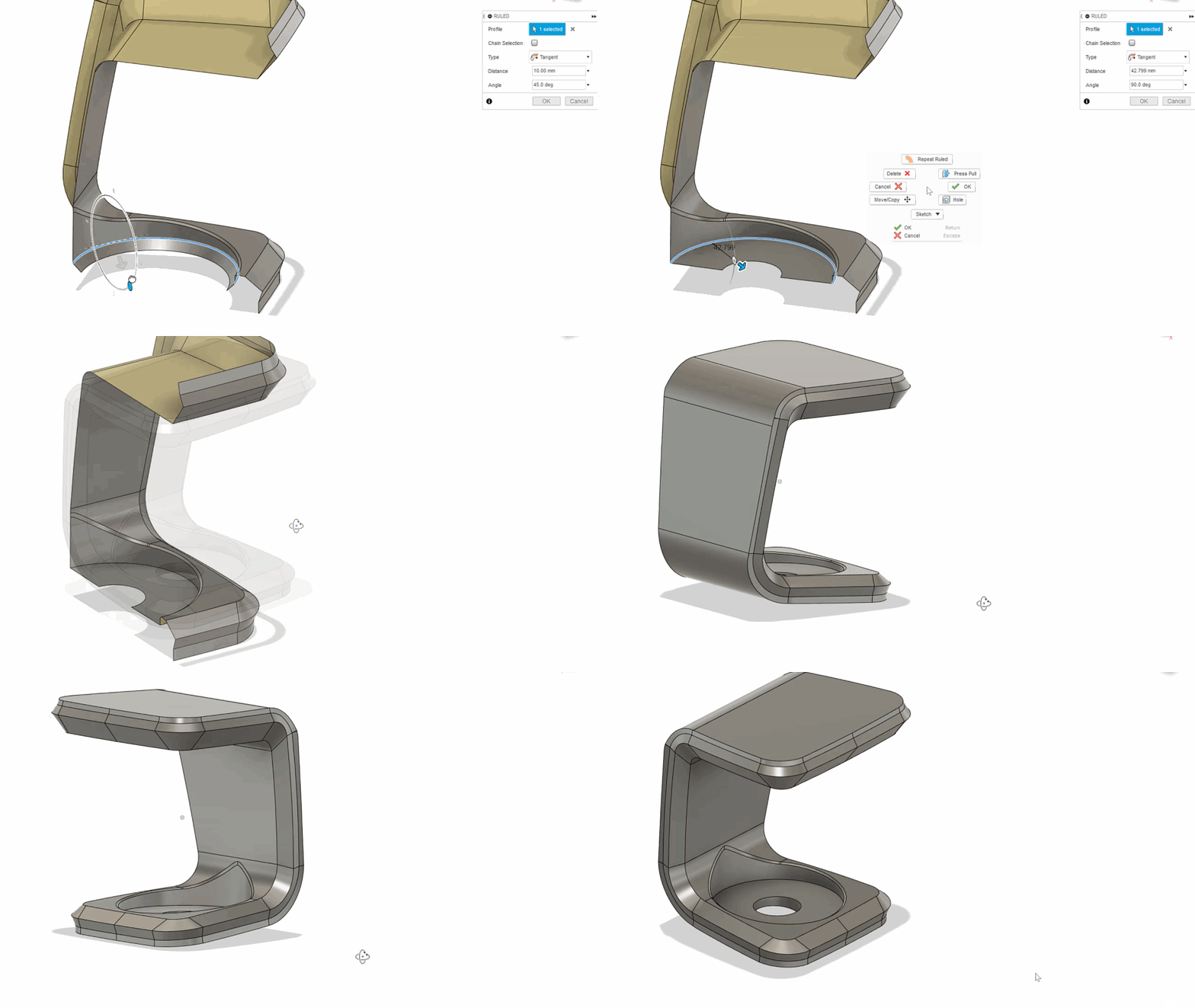
[/expand]
Ruled Surface Help Documentation
[icon name=”thumbs-up” class=”” unprefixed_class=””] Improved! Select Two Points now available in Straighten Command
Design workspace > Create Panel > Create Form > Modify Panel >Straighten

Based on your feedback, we’ve also improved how you can better straighten T-Spline edges. Using the previously available options (Fit/Line/Parallel Line), it was difficult to straighten edges with the two ends fixed. Now using the Two Points option, you can pick two ends (T-Spline vertex, tangency handle, sketch point, work point, or B-rep vertex) and then pick T-Spline vertices in between the clamped ends.
[icon name=”info-circle” class=”” unprefixed_class=””] [expand title=”See it in action”]
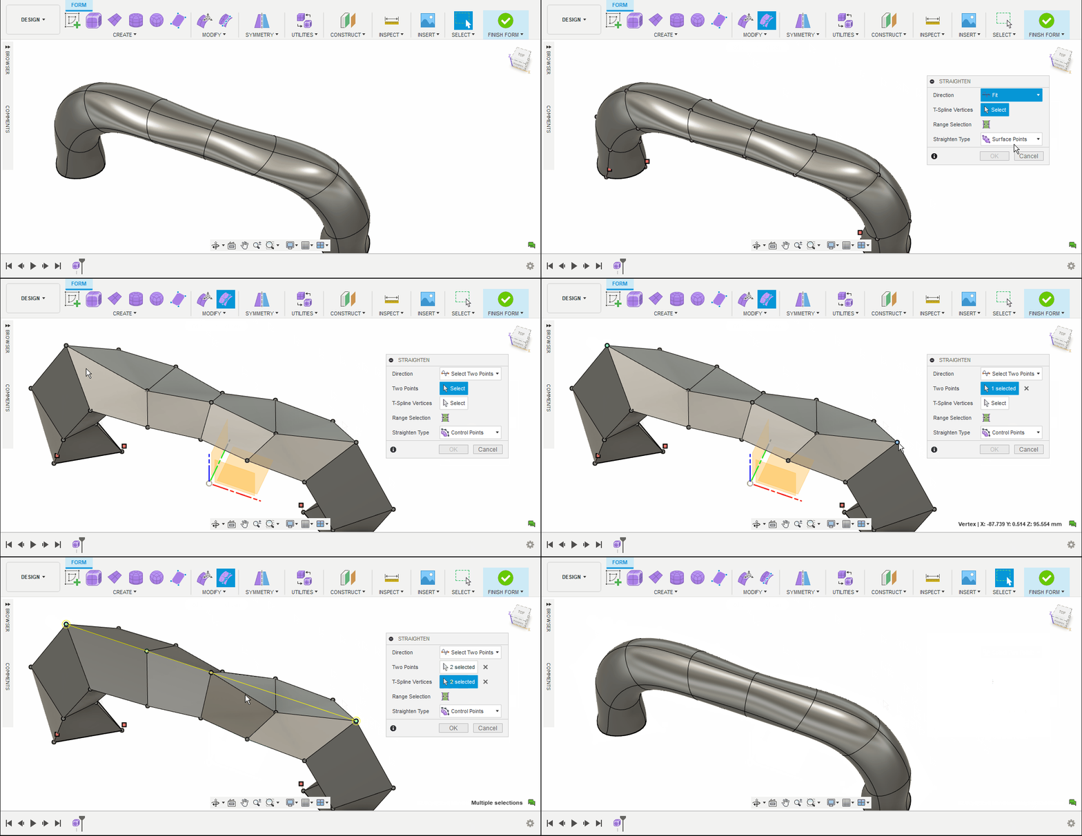
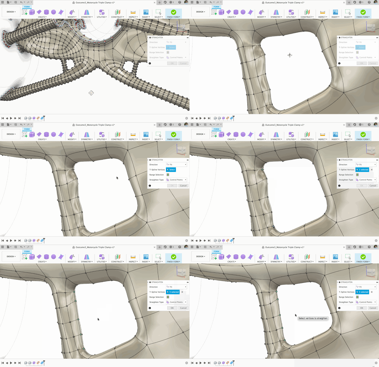
This will make it easier to straighten out those bumpy generative design struts.
[/expand]
Straighten > Two Points Help Documentation
[icon name=”thumbs-up” class=”” unprefixed_class=””] Improved! Curve Matching T-Splines

The T-Spline Extrude/Revolve/Sweep commands had previously never been 100% accurate at matching T-Spline edges to a desired spline curve…until now. We’ve made improvements to each command and now it will accurately matches T-Spline edges to the desired sketch. Note: To take advantage of this improvement, use a degree-3 spline curve (Sketch > Create Panel > Spline > Control Point Spline > Degree 3).
[icon name=”thumbs-up” class=”” unprefixed_class=””] Improved! Open the source design from a derived design
Browser > Right-click on a derived design and select Open Source
Last year we introduced the concept of derived components (Create Panel > Create Derive) or inserting a derived component (Insert Panel > Insert Derive). This gave you the ability to work on the derived component without affecting the source component. There also wasn’t an easy way to access the source design if you were working on the derived part either; you had to know exactly where that design came from or go digging in your projects.

Now you can right-click on a derived component in your design and select Open Source to open the original source design that the derived part came from. This will open the design in a separate design document.
[icon name=”wrench” class=”” unprefixed_class=””] [expand title=”Issues Fixed – Click to expand”]
- If you have sketch dimension visibility turned on for a given design, Fusion 360 will now remember it and maintain that visibility across sessions, users, or simply closing and reopening the design. Thanks teknoel for the tip!
- HughesTooling told us about a dimensioning bug where he wasn’t able to select a midpoint constraint for dimensions if it was already used by another constraint. This shouldn’t be the case, and now it’s fixed.
- Vpgguitars reported an issue where Fusion 360 was becoming unstable when he tried to join 2 components together with a joint origin. As we dug into this, we discovered some funny business in direct modeling and was able to reproduce the issue. We’re happy to report that this issue is now fixed.
- Intuos5 found an issue where activating and deactivating spline handles still left a ghosted spline profile in the background. Turns out Fusion 360 was not recomputing the profiles (as it should) when a tangent handle was deactivated. Now it does.
- We squashed a bug that was causing Fusion 360 to freeze when you copied a sheet metal body and performed a “paste new” action in a sub-component of an activated component.
- Our support team told us about an issue where the Sweep command did not follow the Path set when coiled around a cone shape. Now it’s fixed.
- Zevster discovered a weird issue where the loft mapping made on a design was lost when zevster was trying to edit the Loft feature from the timeline or was reopening the design after having saved it. We untangled some wires and made sure that Fusion 360 remembers to leave your edits alone.
- We sorted some long-overdue Variable Fillet bugs. HughesTooling found a bug where dragging the arrow on one edge unexpectedly placed the fillet on the opposite edge. Now when the experience should work as you’d expect it to.
- Mhoff67 was trying to do some engraving when he tried to extrude a profile from a tangent construction plane on to a cylinder with the starting point set to “From Object” and found that the extrude command failed. Sorry about that; we got this sorted out now it’s good to go again!
- Scott Moyse pointed out a long-standing issue that annoyed all of us; we’re happy to report that it’s finally fixed! When you use the Measure tool and take multiple measurements where 2 values are showing, they will no longer overlap each other. Hooray!
- Speaking of long-standing issues, just look at how old the UI was when HughesTooling reported this one! If you used the Hole command and made holes based on sketch points, then Fusion 360 didn’t allow you to reselect new sketch points and fix the lost references if said original sketch points were deleted. Now you can.
- Working with our support team, we’ve improved the Insert > DXF command to accept points-only DXF files.
[/expand]
Generative Design
Explore unlimited outcomes with the Generative Design Extension
Based on the feedback we’ve gathered from talking to you, we’re launching the Fusion 360 Generative Design Extension, and it is now available as a monthly or annual subscription. Subscribing to the extension will give you unlimited access to solves and outcome downloads, within the period of your extension subscription. You can still pay-per-outcome just like you used to do if you choose to, but this new additional option is great for those of you using generative design on a regular basis or have a fixed project budget.
This offering can be purchased from within Fusion 360 from the extension manager or from our website.
This offering is also available through our sales team as well as our affiliated resellers, so if you’ve bought subscriptions through them, contact them and ask them about this offering.
Contact our sales team for a demo
Locate your reseller
[icon name=”star” class=”” unprefixed_class=””] New! Fully burdened cost calculations
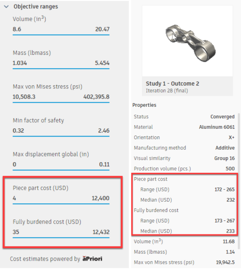
Expanding on the information provided by the aPriori cost estimation engine, you will now see fully burdened cost information for all outcomes where cost is estimated. You will also notice that what we used to refer to as “Estimated manufacturing cost” has now been renamed to “Piece part cost” to more accurately reflect what it represents.
Cost Estimation Help Documentation
[icon name=”star” class=”” unprefixed_class=””] New! Materials now show cost icons

As we continue to improve our workflows around cost estimation, we heard from many of you that it was hard to understand what materials would generate cost estimates for what manufacturing methods. We totally get it, and that’s why you will now see a calculator icon next to the materials that will generate cost estimates for a given manufacturing method. Stainless Steel – 17-4 PH and Inconel 718 Plus, recently added in our May product update, will also show costing calculations.
Select Material Help Documentation
[icon name=”star” class=”” unprefixed_class=””] New! Support for sending outcomes to Ansys Discovery 2020 R2
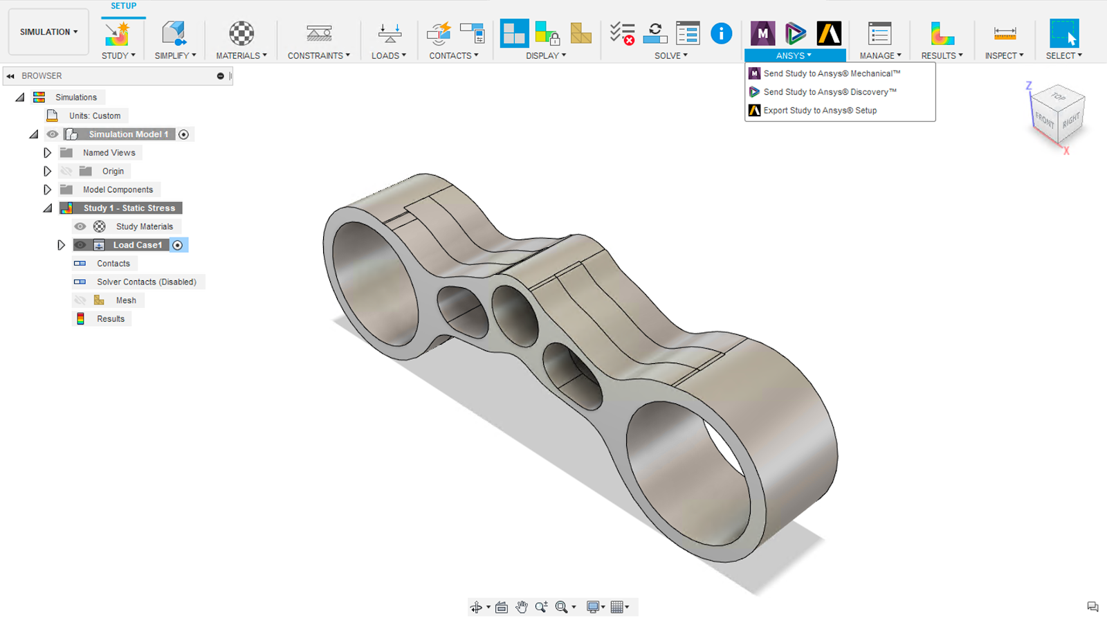
We are continuing to grow our partnership with Ansys. Since January, we have been able to send generative design outcomes from the Simulation workspace to Ansys Mechanical 2020 R1 with a full setup ready to analyze. We are now expanding this workflow to allow users to send generative design outcomes to the upcoming Ansys Discovery 2020 R2 release.
[icon name=”leanpub” class=”” unprefixed_class=””] Learn Generative design with new tutorials
- Self-paced learning
From Fusion 360: Help > Learning & Documentation > Self-paced learning
From the Fusion 360 website: Learn & Support > Self-paced learning
[icon name=”info-circle” class=”” unprefixed_class=””] [expand title=”Learn more”]
A new generative design learning path is now available on the Fusion 360 Self-paced learning page. The path’s objective is to provide a coherent learning journey for new users of Fusion 360 Generative Design. The path includes a series of five courses that guide you through the generative workflow, key features, and concepts. Each course contains several video-based lessons, produced by the various teams who support Autodesk customers in using Generative Design.
The lessons show a variety of models that are suitable for Generative Design and answer the most-frequently asked questions about it. Additionally, the path covers the Fusion 360 basics for those you starting your learning journey with Fusion 360 We recommend that you complete the five courses in sequence for the best experience.
[/expand]
- Inventor-based Generative Design tutorial
Data Panel > Samples > Generative Design Samples for dataset
Help documentation for tutorials steps

We put together a new generative design tutorial to help those of you who are also using Inventor understand best practices for using Inventor and Fusion 360 together for generative design. If you are only a Fusion user, don’t worry, there is plenty of good stuff in this tutorial for you, as well. If you’re familiar with Inventor, be sure to look at your Inventor Guided tutorials to check out the beginning and end of this 3-part tutorial.
[icon name=”info-circle” class=”” unprefixed_class=””] [expand title=”Learn more”]
Like all of our generative design tutorials, you can find this new tutorial in the data panel under our Generative Design Samples section with files that are “Ready to Generate” and “Ready to Explore”. Also, you can find examples of outcomes that have already been exported for selected manufacturing methods. You can open them and start learning at any point you want. After you’ve got the design opened, head over to our help center to access the step-by-step tutorial: https://help.autodesk.com/view/fusion360/ENU/?contextId=INV-FUSION_TUT
[/expand]
Electronics Design
This update includes electronic design capabilities that will significantly optimize your design efficiency. We’ve made some major (and innovative) improvements such as polygon floods, quick route layer option, and new functionality that will take your electro-mechanical workflows to the next level.
[icon name=”star” class=”” unprefixed_class=””] New! Polygon Copper Pour Workflow
Electronic Design > 2D PCB > Polygon

You now have access to new Polygon commands, with the three major ones being Polygon Pour, Cutout, and Shape. The previous Polygon methodology stroked the interior of the polygon with overlapping line segments, which was a rather outdated approach. The new Polygon Pour experience takes a more conventional approach of creating simple filled solid shapes defined by their edge outlines.
[icon name=”info-circle” class=”” unprefixed_class=””] [expand title=”Learn more”]

You can begin by using Polygon Shape to create areas of the board for specific purposes, like a spot serial or version numbers.
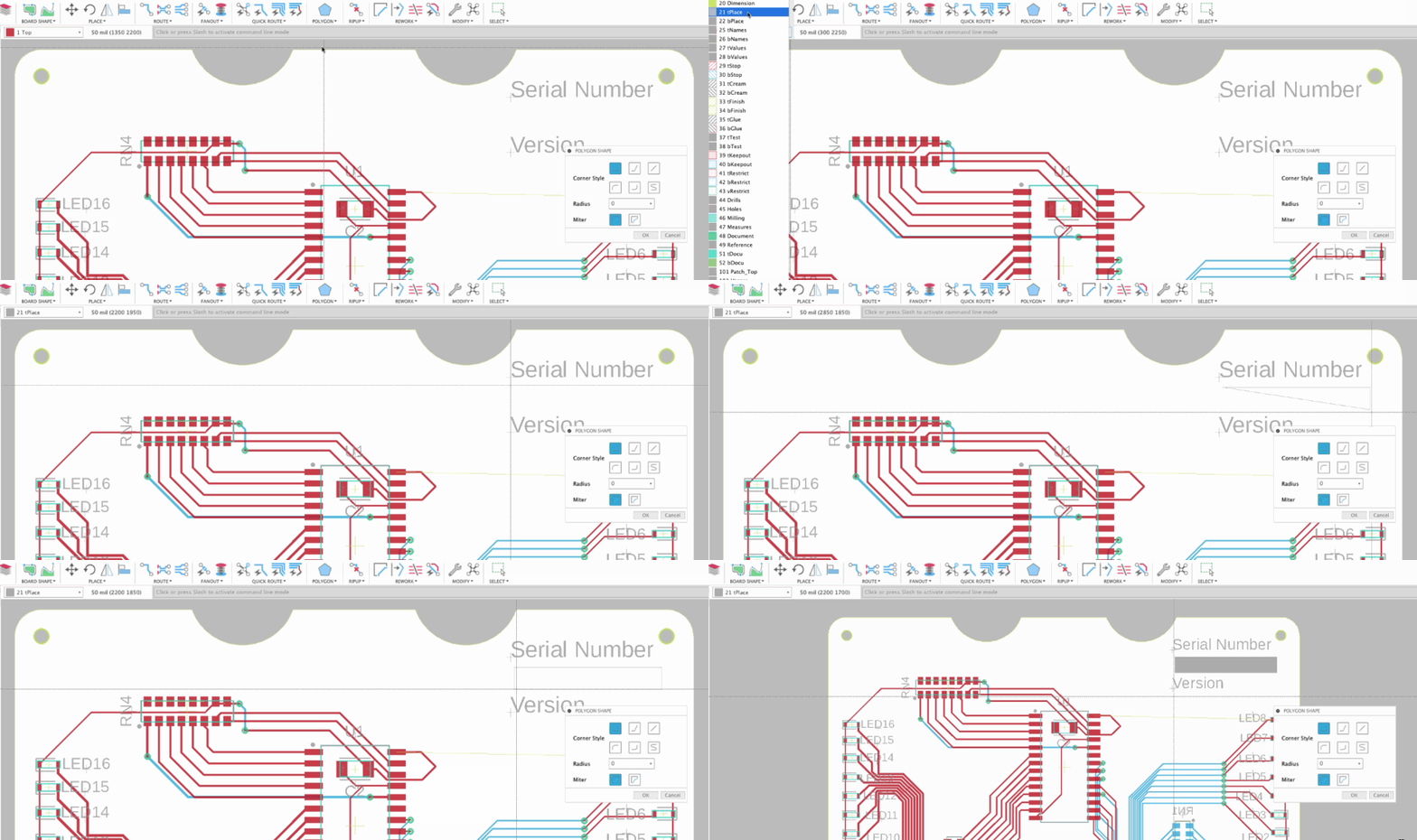

Polygon Pour will allow you to fill the board with copper pour based on the area you select. It will intelligently isolate areas that don’t belong to the polygon.
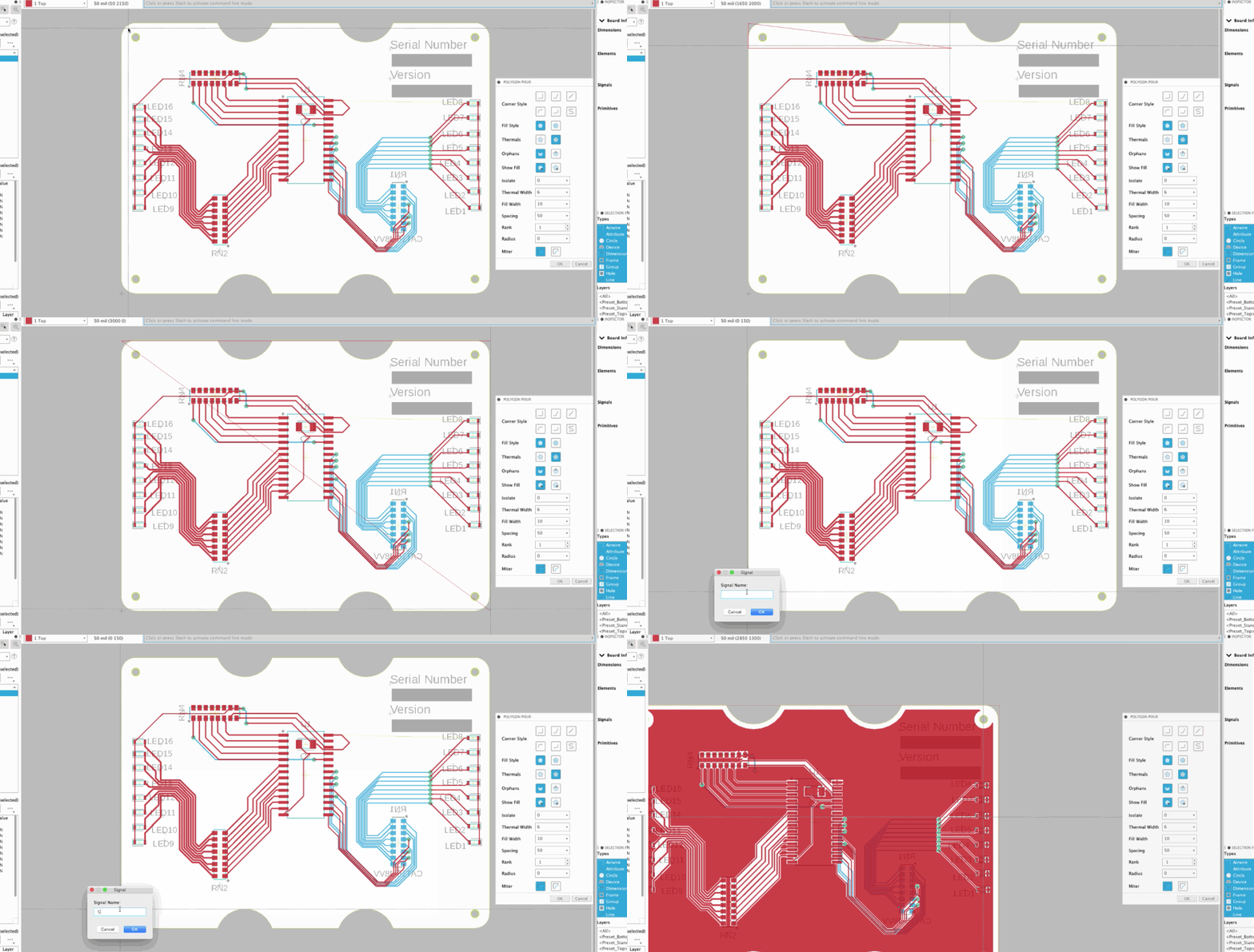
If you decide to move a component, the pour will automatically update based on that move. This intelligence is what sets it apart from the rest.
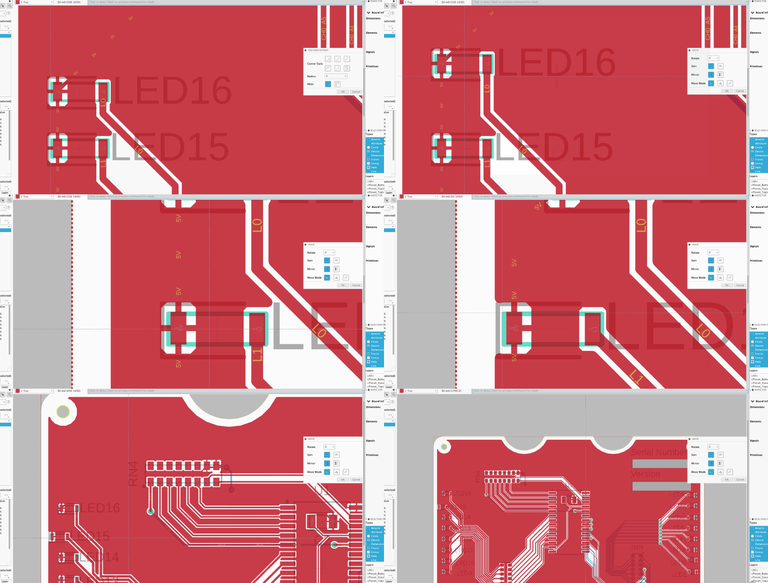

[/expand]
[icon name=”star” class=”” unprefixed_class=””] New! PCB Derive
Design Workspace > Solid Tab > Create Panel > Derive PCB from Sketch

One of the essential uses in the electromechanical workflow is for the mechanical engineer to provide the required geometry to layout the circuit board outline. Many applications require converting file formats, which have proven to be inefficient and prone to errors. With Fusion 360, you can select manually drawn sketch profiles or projected enclosures surfaces. The selected profiles geometry is used to define the 3D PCB editor, which is linked to the PCB layout editor. This efficient collaboration process enables mechanical and electronic engineers to be aligned.

Modification to the enclosure required the recapturing of the sketch profiles. With the PCB Derive option, changes to the sketch profiles will automatically update the PCB layout geometry.
[icon name=”star” class=”” unprefixed_class=””] New! Link and Unlink of Managed Libraries
Electronic Library > Manage
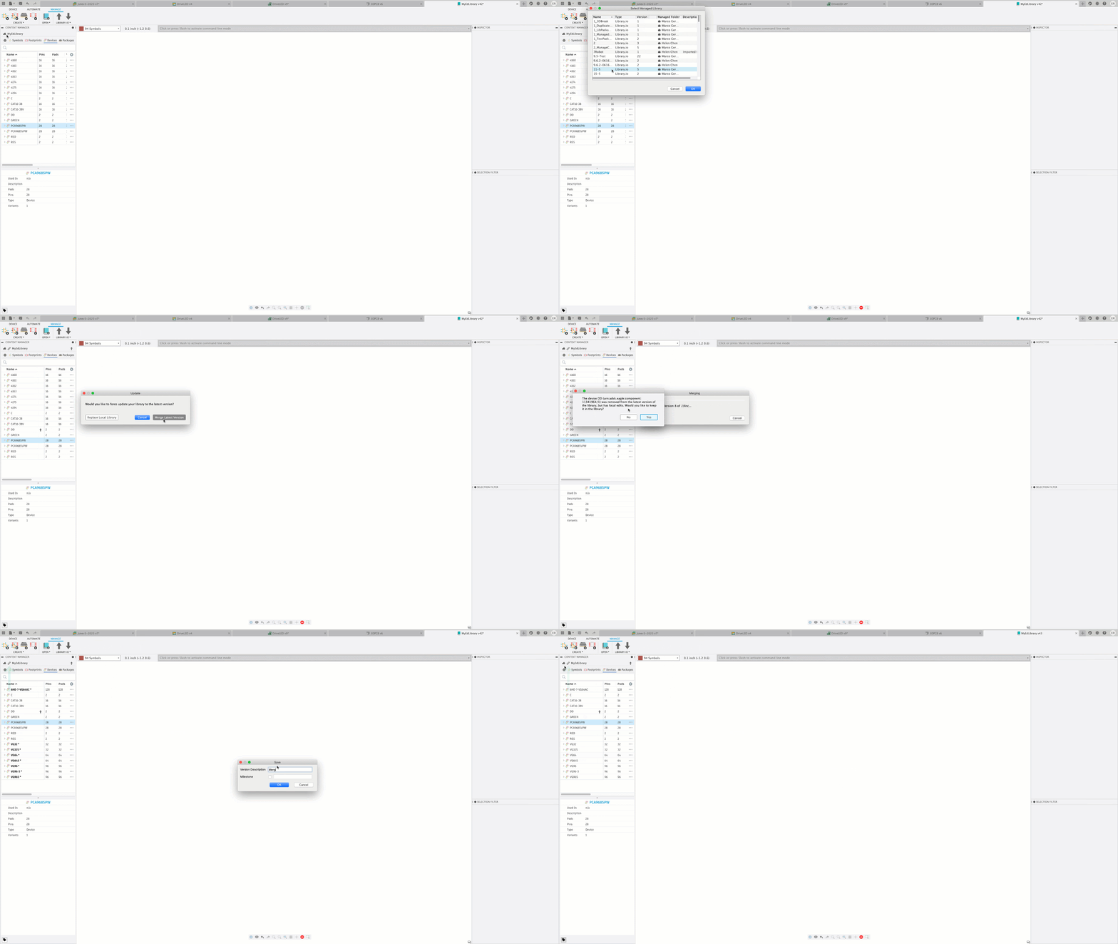
If you are an EAGLE user, it’s possible you have created managed libraries that way you can remotely access them and map 3D models to your footprints. If you have Altium or OrCAD libraries, you can visit library.io and upload your libraries to have them converted into a Fusion 360 compatible format. Managed or uploaded libraries converted libraries are accessible through Fusion 360 electronic editors.
[icon name=”star” class=”” unprefixed_class=””] New! Bulb Chip LED
Electronic Library > Footprint > Package Editor

The existing IPC Compliant package generator provides a large amount of templates by which creating Footprint and mapped 3D models can simply be accomplished by transferring the mechanical details from the component data sheet. Many of the templates have additional options, you will now notice that in the Chip LED template there is a domed option. Component body color can also be specified using HEX RGB colors for a more customizable look and feel.
[icon name=”thumbs-up” class=”” unprefixed_class=””] Improved! Quick Route workflows now supports Multi Layer
Electronic Design > 2D PCB > Quick Route Panel > Quick Route Guided

Quick Route Guided now has an easier interface that will give you a better idea of the intended path for the selected signals. After selecting the signals, right click where you wish to begin the path, after defining the path press enter to finish the route.
With Quick Route active, selected signals are routed or existing traces are optimized. Until now Quick Route was limited to the active layer. With the latest update, you are able to use Quick Route on signals connecting components that are on opposing layers. The available options are: active layer, any layer or specific layers. The DRC layer stack-up determines the layers available for all Quick Route options.
[icon name=”thumbs-up” class=”” unprefixed_class=””] Improved! Reuse existing 3D models for footprint
Electronic Library > Footprint

When adding a 3D model to an existing footprint, you now have the option to reuse an available 3D model for that footprint. This should make it more flexible for you to leverage the designs you already have, and not waste time remaking or looking for the part.
[icon name=”thumbs-up” class=”” unprefixed_class=””] Improved! UI Performance
As we continue to mature the electronics design workflows, we’re also improving the UI performance, how it scales and how fast it loads going from one environment to the other. benL9LDN told us that when he was using some command scripts his team had developed for doing LED matrices in Fusion 360, the scripts were executing correctly but were running sub-optimally slow. With our UI performance improvements, both board scripts and schematic scripts run a lot faster now.
[icon name=”wrench” class=”” unprefixed_class=””] [expand title=”Issues Fixed – Click to expand”]
- We fixed a Mac-specific issue where the outline of the board was incorrectly changed in 3D PCB after the change was pushed from the 2D PCB environment.
- Apselektronik and a few others told us that the “Create 3D PCB” option was not available to them under the Create drop-down menu. Turns out it was missing in the menu if you had a design open with no design history (timeline turned off). We’ve now added this option to both direct as well as history modeling modes.
- Our support specialist Karina told us about an issue she heard from a customer, where the PCB board shape wasn’t updating correctly based on changes made to the sketch. We later found out that Fusion 360 had an issue with elliptic arcs and wasn’t supporting it correctly. Now it does and these changes should propagate smoothly.
- We fixed a crash issue that many of you have been reporting, where closing the PCB and schematic document tabs in a specific order caused Fusion 360 to become unstable. This will no longer happen, and we’re glad to have finally resolved this issue.
- robert.seliger told us about an issue he was having where the edits he made to the schematics of his electronics design were not being saved properly, and when he went back to the schematic, the edits were nowhere to be found. We quickly dug into this and fixed the issue. Thanks Robert for reaching out, we’re glad that we’re able to get this sorted!
[/expand]
Drawings
Check out Rob Cohee’s overview video as he goes through what’s new in Drawings (or if you don’t feel like reading).
[icon name=”thumbs-up” class=”” unprefixed_class=””] Improved! Object dragging
Drawings environment > drag a view with your mouse
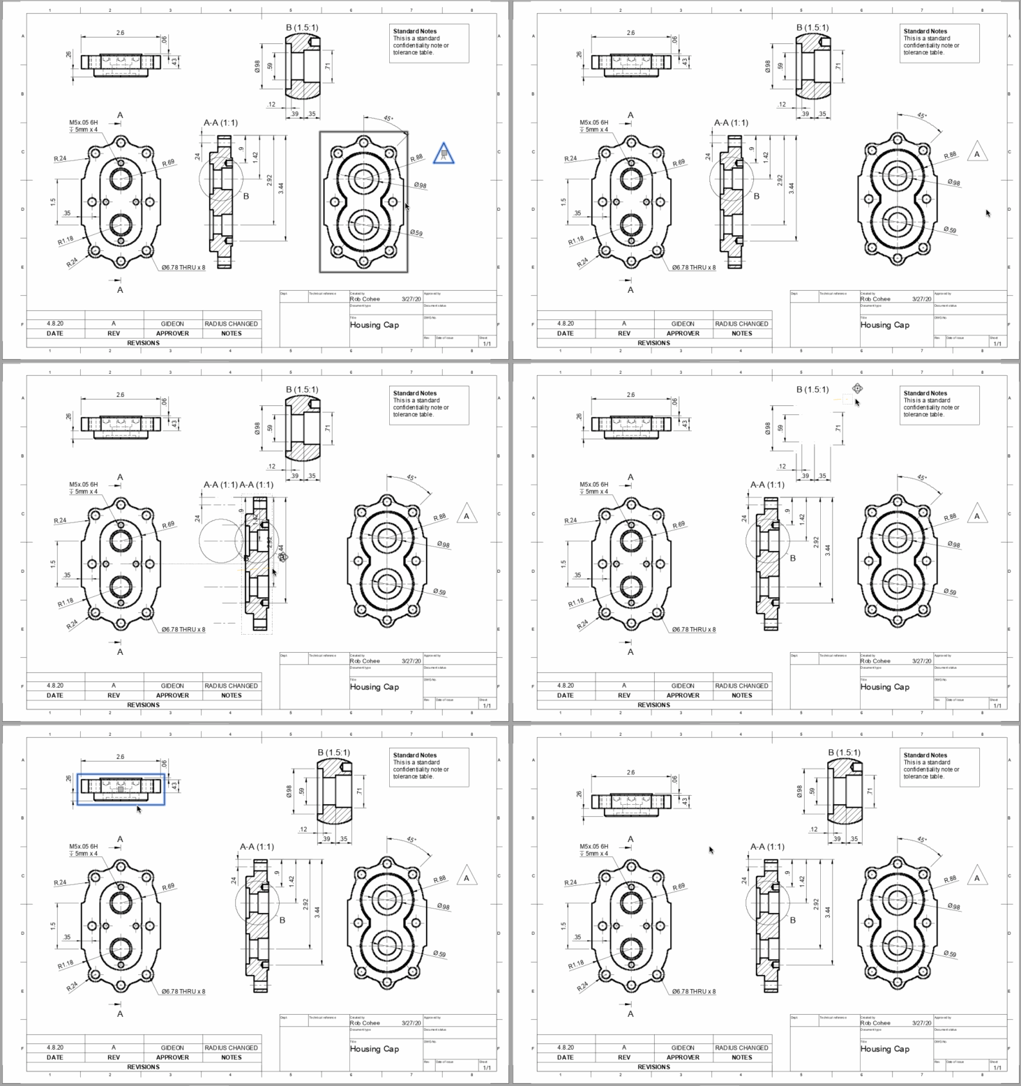
We’ve heard from many of you saying that the interactions in the drawings workspace simply feels different from the rest of Fusion 360, and we totally hear you. It feels that way since much of the code was based on AutoCAD, where moving and dragging entities required you to use object grips. Over much of the last year and the beginning of this year, we’ve been working hard on sorting this experience out, completely rewiring the architecture so that the interactions feel more intuitive. Now you can just click, drag, and move views, text, and sketches around a sheet, much like how you move entities in the rest of Fusion 360.
We’ve also simplified the way views highlight, which will avoid a lot of unnecessary and distracting “flashing” as your cursor moves across each view. A much cleaner experience overall!
[icon name=”thumbs-up” class=”” unprefixed_class=””] Improved! Switch Linear Dimension Units (mm / inch)
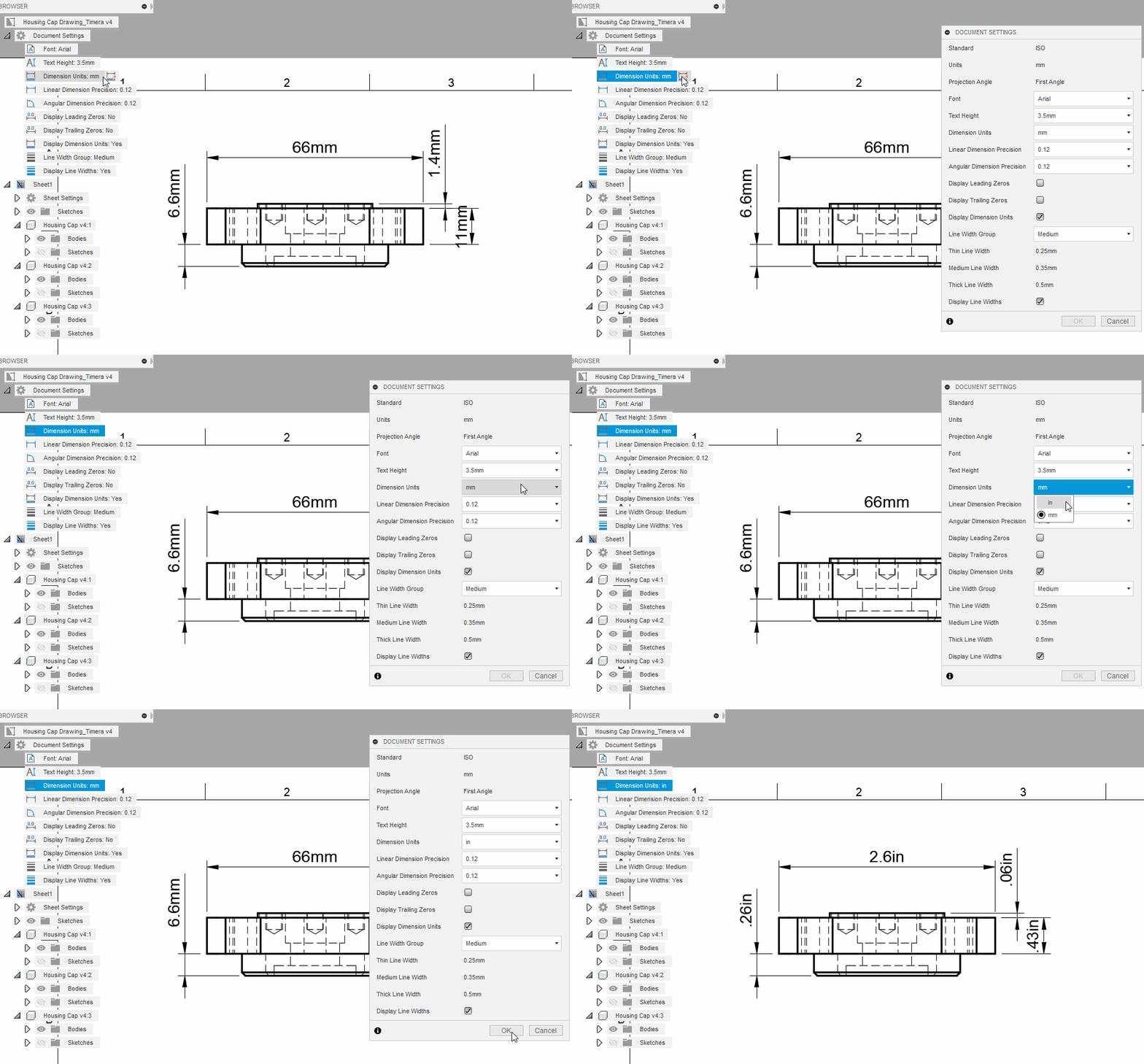
Historically, Drawings units set upon creation were inflexible thereafter. This long-requested option to toggle document settings between mm and inch units will be a huge time saver for those of you making edits after the drawing has been created, or if your clients come to you with differing requirements.
Dimension Unit Switching Help Documentation
[icon name=”thumbs-up” class=”” unprefixed_class=””] Improved! Rename Views

We’re excited to bring you more flexibility by enabling view renaming for section and detail views. Gone are the days of using clumsy workarounds or being forced to restart in order to change a section or detail view name after reordering – a new Name field in the Drawing View dialog now allows you to quickly change from the default when placing a view, or when editing afterwards.
Section Views Help Documentation
Detail Views Help Documentation
Drawing Views Help Documentation
[icon name=”thumbs-up” class=”” unprefixed_class=””] Improved! Create Drawing from Visible Only

Along the same theme of bringing increased efficiency and flexibility to Drawings, we’ve upgraded the creation workflow with a ‘Visible Only’ reference option. This will save you time previously required to select the desired components to display in a new view by capturing your intent via the visibility state in the Design. The default for Contents in the Create Drawing dialog will update contextually based on the command access point and components’ state.
Creating a new drawing from a design
[icon name=”thumbs-up” class=”” unprefixed_class=””] Improved! Line-width control in Sketch dialog
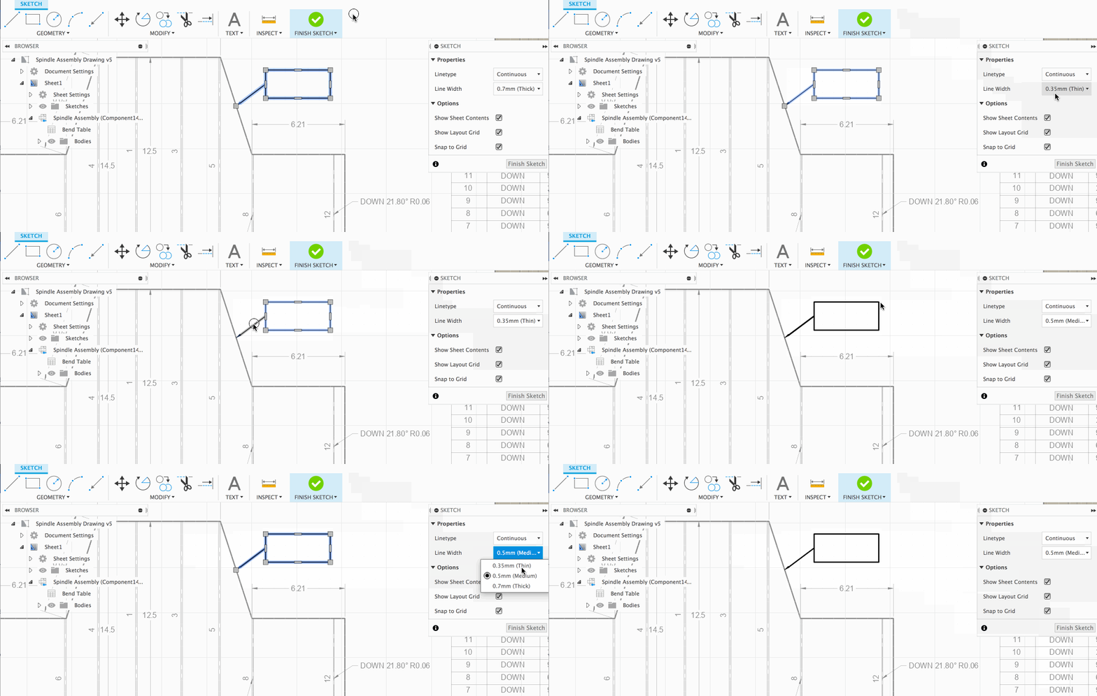
The May product update finally gave you the option to adjust the line widths of your entire drawing so that you see exactly what you’ll get from a PDF output. Now you can control the line width of individual sketch entities by using the Sketch palette, either before creating a new sketch entity or afterwards. Choose between Thin, Medium, and Thick.
Drawing sketches Help Documentation
[icon name=”thumbs-up” class=”” unprefixed_class=””] Improved! Drawing Template now easier to access

The ability to create drawing templates, save them, and reuse them for new drawings have been available in Fusion 360 for quite some time, but not many people know about it. We’ve now added the option to create a new drawing template to the top level in the File Menu for easier access.
[icon name=”info-circle” class=”” unprefixed_class=””] [expand title=”Learn more”]

We’ve also made our “smart” template capabilities more prominent. When you create a new template, you are automatically prompted to place a base view; this base view is a “placeholder”, and when you later use this template to create a drawing, a base (or projected) view of your design will take its place. To indicate this “smart” capability we added lightning bolts to icons when in template edit mode.
[/expand]
Drawing templates Help Documentation
[icon name=”thumbs-up” class=”” unprefixed_class=””] Improved! Help content navigation
Drawings Help documentation page

If you haven’t noticed, we’ve restructured the left panel table of contents so that it becomes easier for you to navigate. Previously, content was buried within categories like Concepts, How to’s, Tutorials and Reference. Based on your feedback, we’ve up-leveled topics to the top, where the topics themselves will contain the appropriate concepts and how to’s. Tutorials and Reference will remain where they are.
[icon name=”wrench” class=”” unprefixed_class=””] [expand title=”Issues Fixed – Click to expand”]
Fixed: Balloon and Part numbering
We broke some things with the way parts are numbered, in both parts list and balloon notes, when used on multiple sheets. We’ve got that fixed up now and in most cases simply opening your drawing should display correct numbers. In some cases you may need to delete your parts lists and balloons, and recreate them, if you have been seeing problems with the numbers.
Fixed: PDF output no longer shows unwanted tooltips when symbols are used
We fixed an issue where mechanical engineering symbols would display tooltip-like windows when hovering over the text, after opening the exported PDFs in other applications like Chrome browser, Safari browser, and Adobe Acrobat Reader.
[/expand]
Simulation
[icon name=”thumbs-up” class=”” unprefixed_class=””] Improved! Heat Transfer command can now idealize heatsink design
Simulation > Electronic Cooling Study > Cooling Panel > Heat Transfer


The Heat Transfer command can now intelligently optimize a study based on different types of heat sink density. If your study includes a few variations of heat sinks, say, one with very thin fins (like those CPU heat sinks), then Fusion 360 will automatically idealize the study to account for the change, and reduce analysis time while maintaining the most accurate results possible. This should reduce the amount of tedious/non-meaningful work you have to do, so you can focus on what’s really important: looking at results and killing bad designs.
[icon name=”thumbs-up” class=”” unprefixed_class=””] Improved! Component loading performance in Electronic Cooling studies

For those of you trying out the newly available Electronics Cooling preview functionality in the Simulation workspace, you’ll be happy to hear that we’ve improved the loading speed of the components when your study is solved and you want to view the results. Previously this took awhile, especially if you have a design that had a large number of components to load. Now it’ll most likely take half as much time to load all the components with results.
[icon name=”thumbs-up” class=”” unprefixed_class=””] Improved! Usability consistency
Since the last update, we’ve also updated much of the Electronics Cooling user experience to be more consistent with how the rest of Fusion 360 feels. One of the things you’ll notice when looking at results is that you can now set the center of rotation point just like how you would do it on the model in the other workspaces (click on the middle mouse wheel/button once, click again and hold).

Load/Gravity arrows, as well as selected heat load groups will now stay in place and remain where they are when going from the model to view to the Results view.

We’ve also tweaked the bounding box of the study based on the model so that we can visualize more air flow around the model for better context of what is happening, as shown in the picture above.
Manufacture
[icon name=”star” class=”” unprefixed_class=””] New! Manufacturing Tool Library
Manufacture > Manage Panel > Tool Library

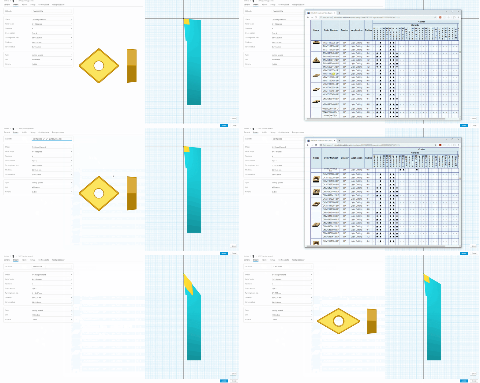
The long-awaited Tool Library refresh is here! After many rounds of feedback and improvements, the new Tool Library graduates from preview functionality to the official release. Along with a fresh new look, we’ve added a ton of new features such as multiple cutting parameters per tool that can be accessed at the operation through “Presets”. We’ve also done a lot of work to turning tool definitions. The ability to copy and paste an ISO code to automatically define an ISO turning insert should be a game changer for anyone using ISO turning tools.
[icon name=”thumbs-up” class=”” unprefixed_class=””] Improved! Even depths of cut in Turning Profile Roughing
Manufacture > Turning Tab > Turning Profile Roughing

In Turning Profile Roughing operations we’ve added the option to make even depths of cut for parts with multiple shoulders. This will help produce more consistent surface finishes and part dimensions while also extending tool life. Without even depths of cuts enabled shallow passes may be created producing thin chips. Thin chips potentially lead to “birds nests” that everyone dreads, coolant starvation, poor surface finishes and poor tool life. When enabled “Even Depths of Cut” ensures that every cutting pass creates an even chip thickness within each machining region.
[icon name=”thumbs-up” class=”” unprefixed_class=””] Improved! Partial hole/boss probing
Manufacture > Probing Tab > Probe Geometry
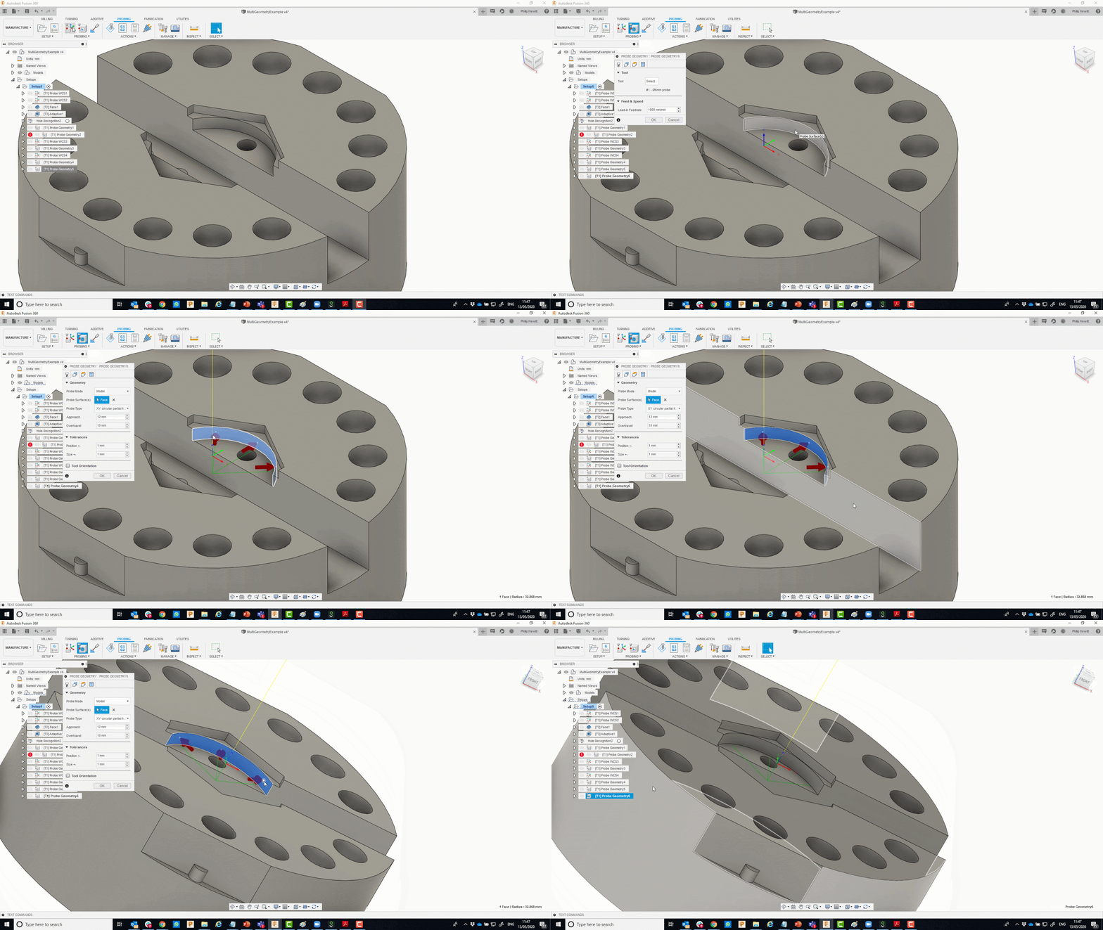
This update enables WCS setup probing for a wider range of geometry by allowing 3 point probing on the arc of a partial hole or boss. The points are automatically spread around the arc but the user can also reposition the points manually. The probing result updates the WCS with the center of the partial feature. The partial circle can also be used in ‘Probe Geometry’ to verify the size and position of partial holes and bosses.
WCS Probing Help Documentation
Geometry Probing Help Documentation
[icon name=”thumbs-up” class=”” unprefixed_class=””] Improved! Angled surface probing
Manufacture > Probing Tab > Probe WCS
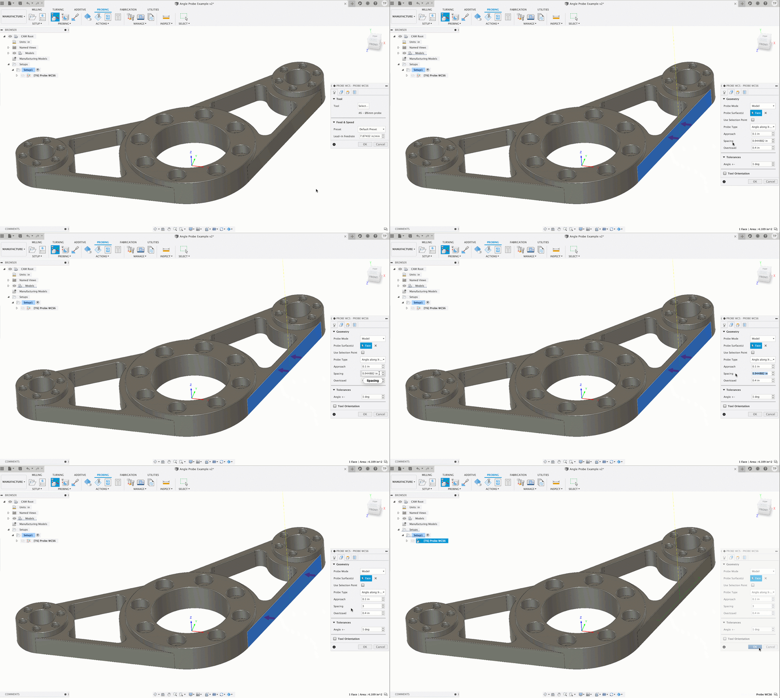
This will enable WCS setup probing for a wider range of geometry by allowing probing of vertical faces which are angled to the X or Y axes. The probing result updates the WCS using G68 or a C rotation. The angled plane can also be used in ‘Probe Geometry’ to verify the angle of vertical planes relative to the X or Y axis.
[icon name=”flask” class=”” unprefixed_class=””] New in preview
- Manual Inspection
Profile > Preferences > Preview functionality > Manufacture > Manual Inspection

Dimensional inspection with manual measuring instruments, such as calipers, micrometers or height gages. Create a Manual Inspection plan with accurate nominal dimensions by selecting features from the model and setting appropriate tolerances. Record measurement results directly in Fusion 360 with a connected digital measuring instrument or by keyboard entry. Fusion 360 stores the results and calculates the deviations between nominal and measured values, and allows you to create an inspection report.
Manual Inspection Help Documentation
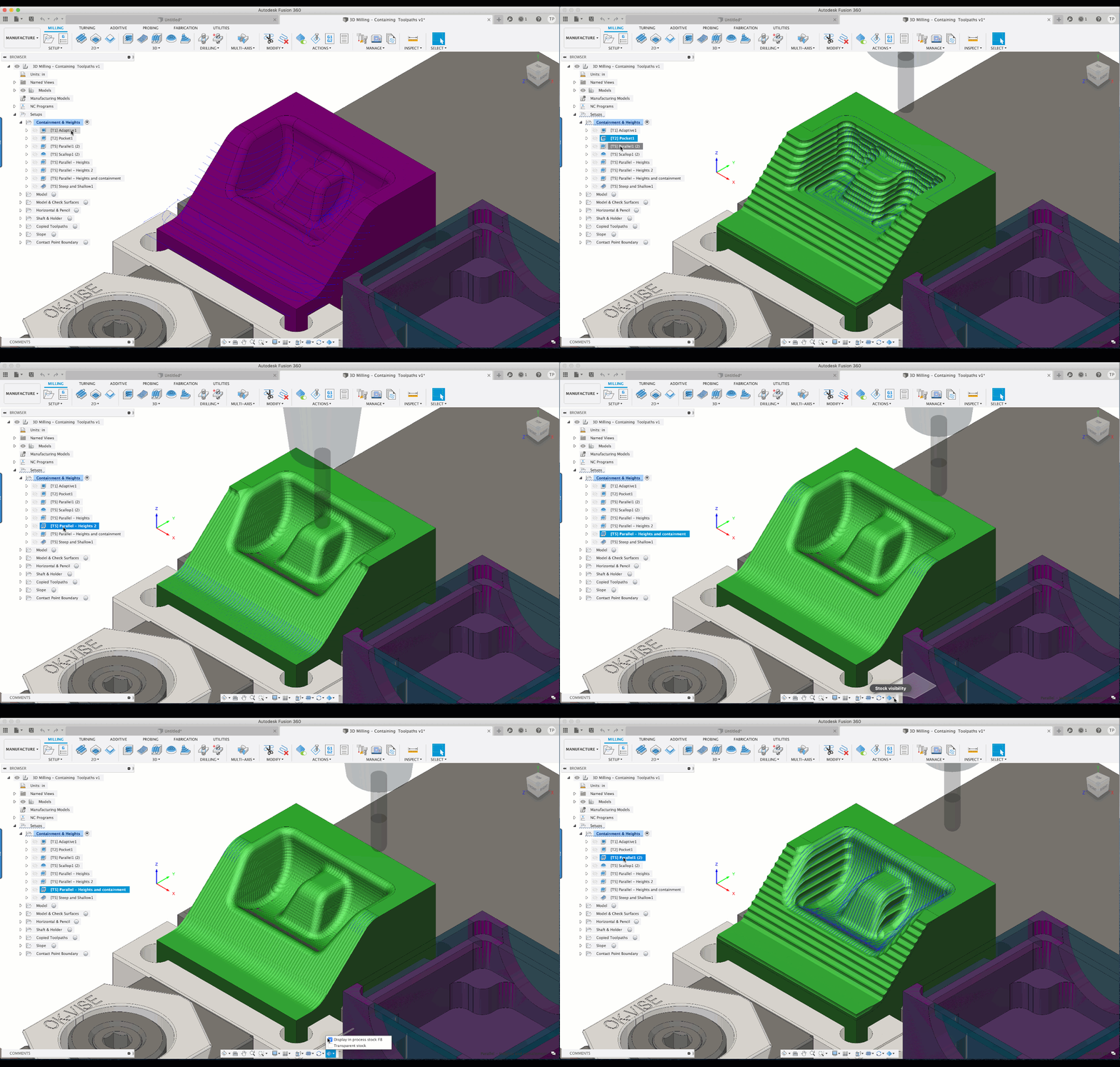
- In-Process-Stock
Profile > Preferences > Preview functionality > Manufacture > Enables caching…

In-Process-Stock allows stock caching to be used for further processing and to be seen from operation to operation. IPS can be paused from the ribbon bar as well as have the visibility turned on or off from the visibility controls at the bottom of Fusion 360.
[icon name=”wrench” class=”” unprefixed_class=””] [expand title=”Issues Fixed – Click to expand”]
- Fixed an issue with certain profile roughing and profile finishing toolpaths that gave an error during
generation. - Fixed an issue with certain profile roughing toolpaths that were not leaving enough clearance on material during a transverse rapid move.
- Fixed an issue where certain profile turning toolpaths were giving the error “invalid contour” on generation.
- Fixed an issue with certain profile finishing toolpaths with tangential extensions not being generated.
- Fixed an issue with certain profile roughing toolpaths that were not machining material up to the stock back Z limit.
- For profile roughing operations, the “Finish Allowance” options were renamed to “Stock to Leave” and for profile finishing operations, the “Leave Allowance” options were renamed to “Stock to Leave”. This was done to keep parameter naming conventions consistent with the milling module.
[/expand]
Additive
[icon name=”star” class=”” unprefixed_class=””] New! Gyroid infill style for Fused Filament Fabrication (FFF)
Manufacture > Additive tab > Infill > Infill pattern
We’ve introduced a new type of infill called Gyroid*, which combines structural rigidity in all directions with its printability and its potential for saving on material without compromising mechanical properties.
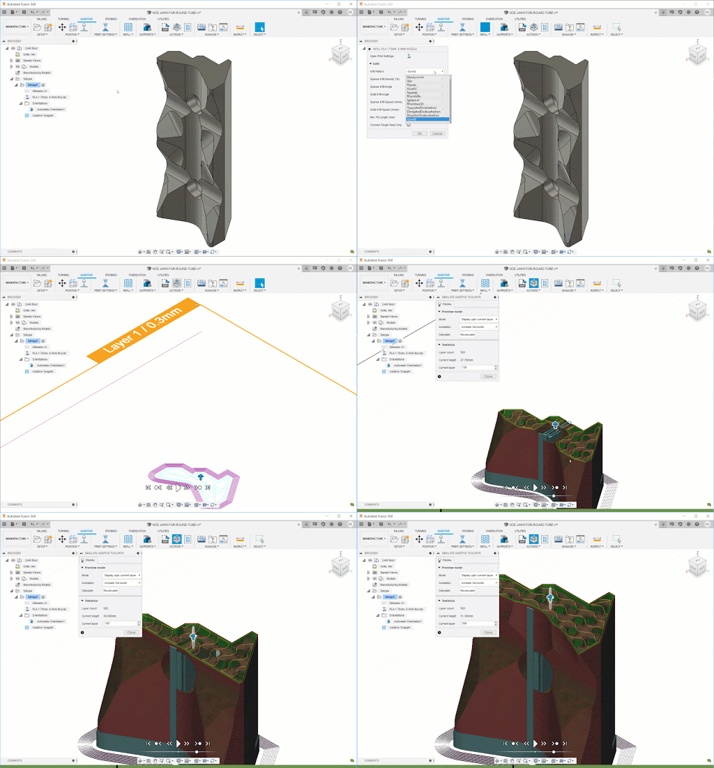
*Note: If your design has an existing selection of print settings, the Gyroid infill option may not automatically be available. To work around this, export the current print settings to a file and reimport that file. If you’re using print settings from the Fusion 360 library, then you should be fine. If you’ve developed your own prints, you’ll want to use this work-around to get the Gyroid infill option. We are aware of this issue and are working on getting it fixed ASAP.
[icon name=”star” class=”” unprefixed_class=””] New! Bresser REX printer added to FFF
Manufacture > Additive Tab > Machine Library

The Bresser REX is a popular WIFI 3D printer out of Germany, and we’re happy to share that it has been added to the list of supported printers for FFF in Fusion 360. It’s a versatile, compact, high quality printer with a print bed of 150 x 150 x 150 mm, which is relatively large for its size.
[icon name=”thumbs-up” class=”” unprefixed_class=””] Improved! Print Setting Library filters
Manufacture > Additive Tab > Print Setting Library

The Print Setting Library now has filters for Technology (FFF or SLM), Layer height, as well Filament diameter options.
[icon name=”thumbs-up” class=”” unprefixed_class=””] Improved! Support actions for Metal Powder Bed Fusion Baseplate

This new support action generates a volume of configurable thickness that follows the shadow area of the part. Baseplates provide a solid interface between the part’s own support structures and the build platform that can help with plate attachment strength, reduce build plate wear, and can even form an attachment point for follow-up machining, for example.
[icon name=”info-circle” class=”” unprefixed_class=””] [expand title=”Learn more”]
- Hatch-type bar supports
A new option for bar contours makes bar supports shaped like flat ribbons that are all aligned along a common angle against the build volume. This can reduce not only the overall count of hatches to render but also the time spent on direction changes in laser travel.

- Add bars to skeleton
A new parameter for the support actions Area with bar support and Adaptive lattice support, enables tracing the centerline of narrow stretches of downskins with a row of bar supports. This option ensures that such stretches also receive support structures.
[/expand]
API
[icon name=”thumbs-up” class=”” unprefixed_class=””] Improved! Import multi-layer DXF into single sketch
We’ve updated our API to now support importing multi-layer DXFs into a single sketch. If you use isSingleSketchResult = True, then the DXF will be imported as a single sketch entity. If it’s set to False, each layer of the DXF will be imported as a separate sketch entity.
V.2.0.8412 (old version)
Manufacture
We fixed an issue where in some cases when you were setting up your Turning tool-paths, Fusion 360 incorrectly showed a warning that read ‘Toolpath has no sections’, even though the toolpath is valid. Once the operation is regenerated, it simulates normally. We fixed this bug and this warning should appear at the appropriate time now.
Using the Fast (3-axis only) Stock mode gave you some really wonky looking simulation stock on macOS, and just won’t even show up on Windows 10. We got this sorted out and now it should show the right stock.
Sketching
A number of you have experienced issues when sketching in the Sketch environment, and have been sending your crash error reports. We got to the bottom of this and resolved this problem – Sketch should be a lot more stable now.
