& Construction

Integrated BIM tools, including Revit, AutoCAD, and Civil 3D
& Manufacturing

Professional CAD/CAM tools built on Inventor and AutoCAD
4 min read
In our previous blog, we showed you how to take advantage of the latest technologies like HDMI, USB 3.0, or DDR by routing differential pairs in Autodesk EAGLE. Now we need to ensure your signals arrive at the same time with the help of length matching. While this technique works great for coupled traces like differential pairs, you might also length match single nets within a bus or chip whose signal timing needs to be exact. We’ll be looking at both scenarios and show you how to use the Meander tool in Autodesk EAGLE to get the job done.
If you’re planning to design a PCB layout that includes Double-Data Rate (DDR) memory, then you’ll be working with not one but two data bit transmissions in a single clock cycle. Big deal, they’ll both arrive at the same time automatically, right? Not necessarily. Because the speed of electrons flying down your circuit is always at a fraction of the speed of light, if you have two signals traveling down two traces of different lengths, then they’ll arrive at different times. When that happens, you’ve got data corruption and signal timing issues.
Whether you’re routing differential pairs or an entire bus for your high speed memory, it’s always critical that the length of your traces are properly matched. You can accomplish this in Autodesk EAGLE by adding delays in your traces with the Meander tool. There are three situations where you’ll typically use length matching:
Let’s look at how to use the Meander tool in Autodesk EAGLE to length match your nets. This process is largely the same whether you’re matching single-ended nets or differential pairs.
We’re going to assume that you already have your single-ended nets or differential pairs routed. Now you’ll need to determine which of your nets within your bus or chip has the longest length and then matches the remaining nets to this length. There are a couple of ways to determine the length of a net, including:
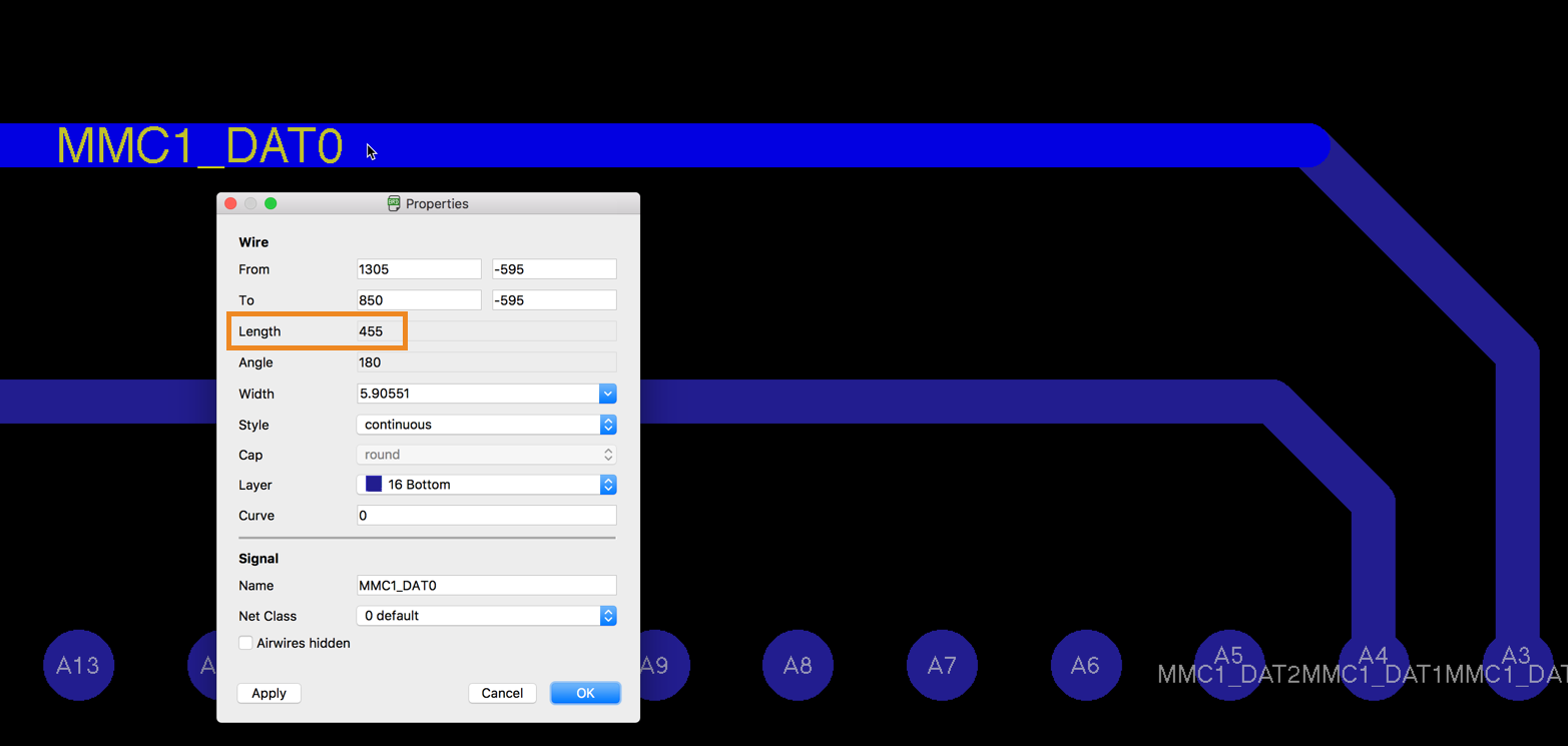
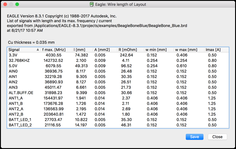
There’s also a handy ULP script that will display basic information for every net on your PCB including lengths, theoretical currents, etc. To run this script type “run length-freq-ri” in the EAGLE Command Line and press Enter. This will open the Eagle: Wire length of Layout dialog showing you all of your traces.
If you need to obtain a specific impedance for your lines then, the length you need isn’t necessarily determined by the longest for your routed traces. In these cases, your length will be determined through calculations or from a signal integrity simulation.
Got your longest net length? Good, now we can meander all of our nets to this length with the Meander tool. Let’s first look at an example with two single-ended, high-speed signals terminating at our memory chip:
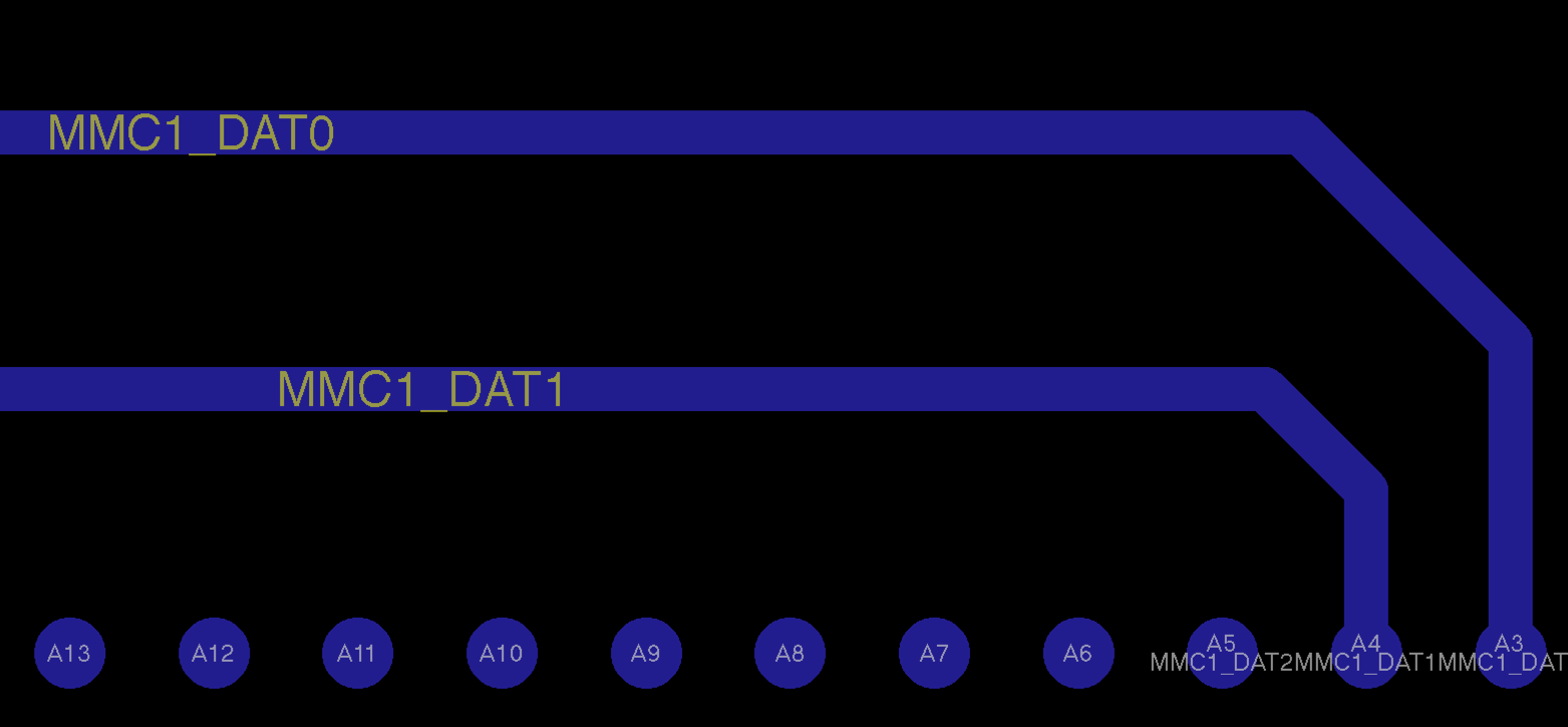
MMC1_DATA0 is our longest net with a length of 455 mils. We can match net MMC1_DATA1 to this length with the following steps:
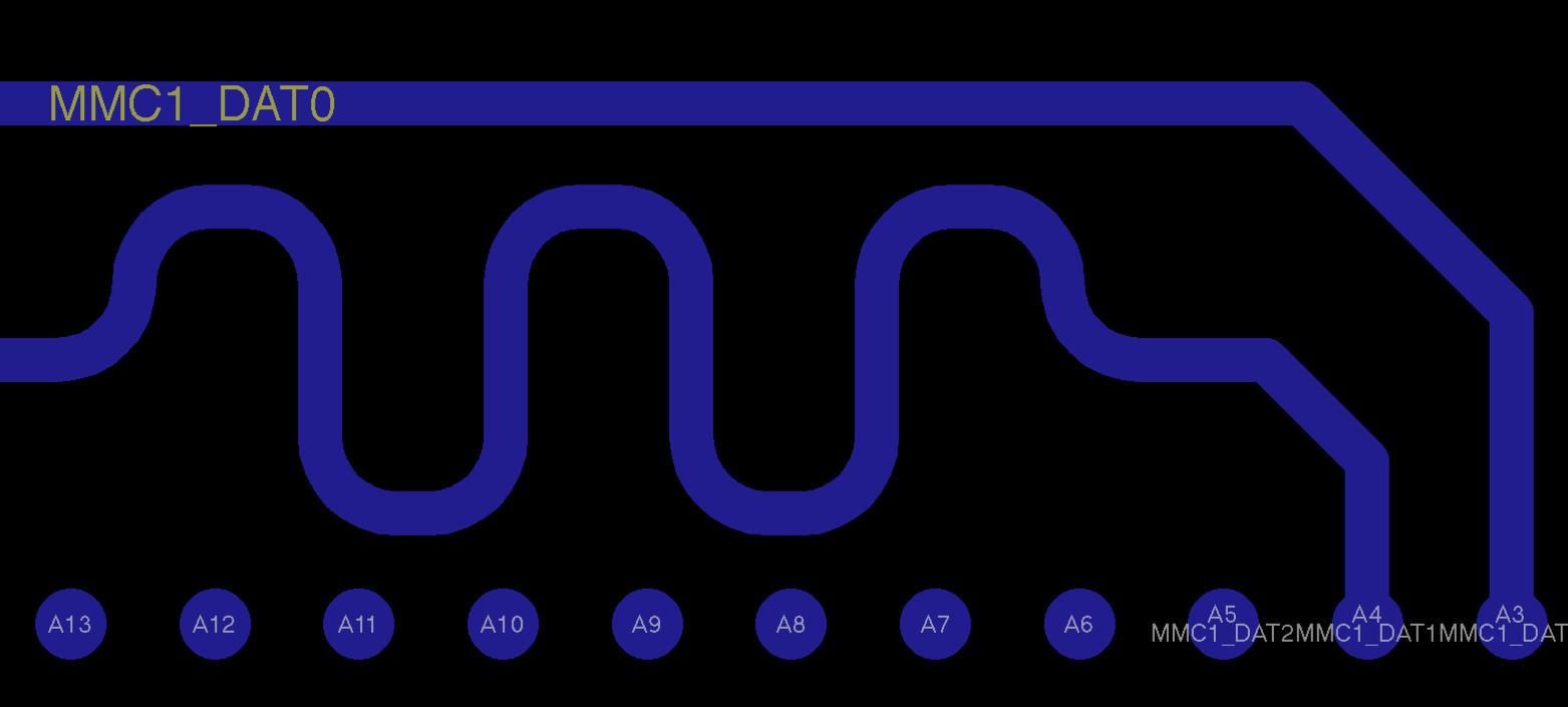
Meandering a pair of differential pairs works the same. Below we have two coupled differential pairs which have been length tuned using the Meander tool ![]() .
.
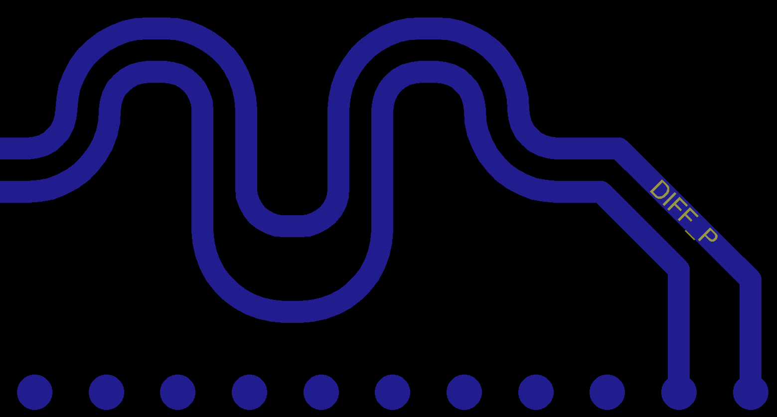
Note that when length matching differential pairs the Meander tool will open a dialog that displays two percentages. The top percentage is the primary trace that you selected with the Meander tool, and the bottom is the coupled secondary trace. Both will be matched to the specified length above the two percentages.

Precise signal timing is essential in any high speed application and ensures that your data arrives as intended at its destination. To make this happen, use the Meandering tool Autodesk EAGLE to balance the lengths of single-ended nets, differential pairs, and groups of nets in a bus or memory block. With all of your nets precisely matched you’ll get to enjoy the inherited benefits, like control impedances and reduced risk of data corruption due to timing.
Ready to start length matching nets in your own high speed design project? Try Autodesk EAGLE for free today!
By clicking subscribe, I agree to receive the Fusion newsletter and acknowledge the Autodesk Privacy Statement.
Success!
May we collect and use your data?
Learn more about the Third Party Services we use and our Privacy Statement.May we collect and use your data to tailor your experience?
Explore the benefits of a customized experience by managing your privacy settings for this site or visit our Privacy Statement to learn more about your options.