Elevate your design and manufacturing processes with Autodesk Fusion
Components and libraries are the heart and soul of every electronics design, and without them, our cherished PCBs would forever remain bare. Thankfully, Autodesk EAGLE ships with a ton of free libraries right out of the box, and there’s a bunch of community-created libraries from the likes of Sparkfun and Adafruit that you can explore. But what happens when you need a specialized part that someone hasn’t already created?
By learning how to create your own parts and libraries, you’ll be able to tackle electronic projects of any shape and size, even if the parts you need aren’t already made. But before you go running off to make them on your own, you’ll first need to understand how libraries work in Autodesk EAGLE.
The Library Hierarchy
Libraries and parts are connected in a simple hierarchy in Autodesk EAGLE. This makes it both easy to understand how everything is organized, as well as how every separate element in a library is connected.
- Libraries. Different part families are nestled within a library in Autodesk EAGLE. For example, if you open the EAGLE Control Panel and look in the main lbr folder, then you’ll see a ton of different library types organized by their family. There’s everything from a general battery family, to more specific families like Atmel.
- Devices. Within every library, you’ll have one or multiple devices. These connect both your schematic symbol and PCB package(s) together in one convenient location.
- Symbols. Within every device, you’ll have a symbol, which is the visual representation of a part that you’ll be using on a schematic.
- Packages. You’ll also have a package, which serves as the physical representation of a part that you’ll use on a PCB layout.
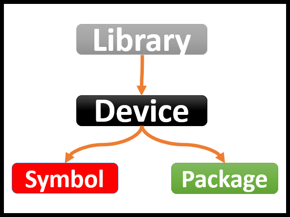
Autodesk EAGLE libraries are organized in an easy to understand manner with devices, symbols, and packages all nestled inside a library.
Let’s take a look at devices, symbols, and packages in more detail to understand what purpose they serve in the world of EAGLE libraries.
The Physical Package
Packages have one of the most important jobs in your electronics project, acting as the physical representation of your part. The package that you create in the digital world will contain all of the metal pads that will be used to connect your parts onto a bare board during manufacturing. And without these packages, your manufacturer would never know where solder paste needs to be applied!
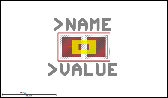
An example of a capacitor package in Autodesk EAGLE.
If you have arrived from another ECAD tool, then you’ll likely recall packages being referred to as footprints or decals. And within an individual package, each metal connector or land pattern on a part is known as a pad. Simple stuff, just a quick change of words to get used to for your journey in Autodesk EAGLE.
Packages come in all shapes and sizes, and you’ll typically find yourself making multiple variations for a particular part in your library. Some packages will also have a particular orientation to be assembled, and you’ll likely be labeling the first pin on larger components like integrated circuits to help out your manufacturer.
The Visual Symbol
Unlike the physical work that a package must accomplish, symbols provide a flat, visual representation of your components for use in a schematic design. And unlike packages, which may have different physical variations, all symbols follow an established system of visual icons that makes them easy to identify regardless of what schematic you’re viewing.
These visual images are split up into two categories, one is based on the IEEE standards for US symbols, and the other is based on IEC standards for EU symbols. Regardless of which icon family you choose to use, you’ll always feel right at home on every schematic, as the symbols will always look the same! You can check out the difference between EU and US symbols with this handy symbol reference guide.

The differences between US and EU symbols can be quite different at times. Here’s a US resistor (top) and an EU resistor (bottom). (Image source)
But what makes a symbol unique? It’s assigned value and name. For example, we can all identify a US-based capacitor by looking for a parallel set of lines. But whether that capacitor has a value of 0.1uF or 1.0pF, or whether it’s the first capacitor in a schematic, like C1, is what makes it truly unique.
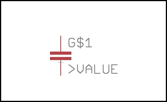
The same capacitor from above, only this time in symbol form.
The Combining Devices
Devices are what holds everything together in an EAGLE library, and it’s here where you’ll be combining your packages and symbols together. By placing both a unique symbol and one or more packages in the same place, you’ll be able to directly connect the pads on your package to the pins on your symbol. This makes it intuitive to place a symbol down on a schematic in Autodesk EAGLE and move onto your PCB layout with the package already linked and ready to go with the right connections.
The Part Creation Process
Creating parts in Autodesk EAGLE will follow a steady flow from start to finish. But before you begin making any parts, you need to get a datasheet for the part you need to create. A simple internet search for “<part name> datasheet” should allow you to find exactly what you need. For example, if we need a datasheet for an NE555 timer, doing a search for “NE555 datasheet” will give us the top result for an NE555 datasheet from Texas Instruments.
Once you have your datasheet, then you’re ready for your part creation flow. This happens in the following steps:
- Step 1 – Creating Your Package. This is where you’ll create the unique footprint for your part with the use of some pads and silkscreen.
- Step 2 – Creating Your Symbol. This is where you’ll create your very own symbol icons, add some pins, and finally give your symbol a unique value and name.
- Step 3 – Creating a Device. This is where it all comes together. Here you’ll connect your symbol and package(s) together, allowing you to link your symbol pins to the pads on your package. And with everything connected, all that’s left is to give your device a name, value, and description.
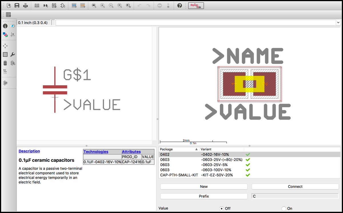
A teaser of how your components will look in their finished form in EAGLE. Here we have a symbol (left), package (right), all organized as a 0.1uF ceramic capacitor device.
Now that you understand how the part creation flow works, and you’ve got a datasheet, let’s get you started by making your very first library in Autodesk EAGLE.
Creating Your First Library
Creating your own library in Autodesk EAGLE will allow you to keep all of your custom made parts in one location for easy access in the future. Here’s how:
- Open Autodesk EAGLE, and you’ll be greeted with the Control Panel.
- Next, select File » New Library to open a Library Window.
- Before creating any new parts, save your library by selecting File » Save (or Cmd + S on Mac and Ctrl + S on Windows).
- Now that your library is saved, you just need to activate it. Go back to your Control Panel, right-click your new library, and select Use. You’ll know if your library is ready to go if it has a green dot next to it in your Control Panel.
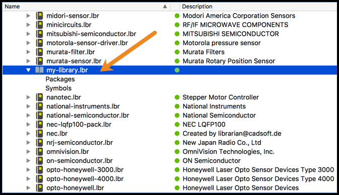
If everything went according to plan, you should have a new personal library folder inside your default lbr folder in the EAGLE Control Panel.
You now have your library folder where you can store all of your newly created parts. We won’t be covering the specifics of part creation in this blog post, but be on the lookout in the future for our Library Basics Series that includes how to create your very own packages, symbols, and devices.
It’s a Parts Party
Creating accurate parts is one of the most important steps in your electronics design process. If you mess this part up, then you’ll likely wind up shipping some design files to your manufacturer and getting back a board with some unpleasant surprises. With some careful attention to detail and planning, you can create parts libraries that will last you years, even decades, and will serve as the foundation for all of your future projects.
Eager to get started with making your own parts? Here’s what you can look forward to in our Library Basics Series:
- Library Basics Part 1 – You’ll begin your journey in parts creation by learning how to make a package.
- Library Basics Part 2 – Your journey continues with creating your very first symbol for use in a schematic.
- Library Basics Part 3 – Your journey comes to an end by creating your very first device, which links your symbol and package(s) together.
All of this part creation is great if you need your own parts, but did you know that Autodesk EAGLE already has thousands of free parts waiting for you to use? Before making a part, make sure someone else didn’t already make it for you! Try Autodesk EAGLE for free today to explore all of the awesome parts libraries available.