Library Basics Part 3: Creating Your First Device in Autodesk EAGLE
Welcome back, Library Pirates! For those of you that didn’t walk the plank and have decided to finish your parts creation journey, you are almost done! In this guide, we’ll be pulling together everything you learned about creating a package in Library Basics Part 1 and creating a symbol in Library Basics Part 2. Now, it’s time to create your very own device, which will serve as the pirate ship for your package and symbol crew. By the end of this blog, you’ll be able to sail the seas of PCB design with a brand new part creation skillset under your belt!
The Datasheet Dance
Throughout our Library Basics Series, you’ve relied heavily on your datasheet for all the information needed to create both a package and a symbol. You’ll need your datasheet again to understand how the pins on your symbol and the pads on your package connect. Here’s the TPS92411 datasheet. For this guide, you need two pages:
Pin Configurations and Functions. This can be found on page 3 of your datasheet and will show the orientation and name of all the pins on your schematic symbol. Checking the image out below, we’ve got:
- Pin 1 – RSET
- Pin 2 – VS
- Pin 3 – VIN
- Pin 4 – DRAIN
- Pin 5 – RSNS
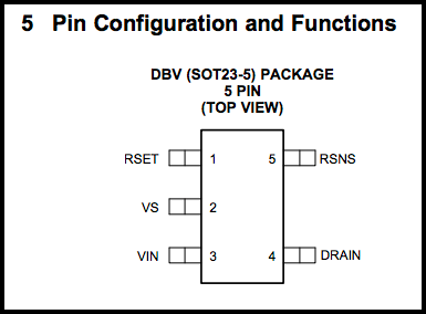
The pin numbers you’ll need for your device, found on page 3 of the TPS92411 datasheet.
Package Outline. This can be accessed on page 24 of your datasheet and shows the orientation of those same pins in their physical form. From here you can go about matching the pad numbers that these pins will rest on to the pin numbers found on your symbol, which ends up being:
- RSET connects to Pad 1
- VS connects to Pad 2
- VIN connects to Pad 3
- DRAIN connects to Pad 4
- RSNS connects to Pad 5
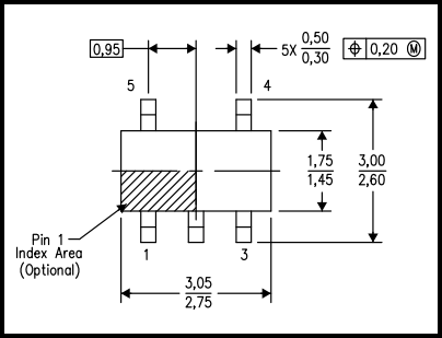
The package outline you’ll need to determine which pad numbers connected to which symbol pins, found on page 24 the TPS92411 datasheet.
By keeping your symbol pins numbered according to your datasheet, you can make creating a device much easier. That’s all the information you need to get started.
Step 1 – Creating Your New Device
Creating a new device follows a familiar set of steps that you should be used to by now after creating a package and symbol. Here’s how:
- Open Autodesk EAGLE, and you’ll be greeted with the Control Panel.
- Select the Arrow icon to expand the main Libraries and lbr folders, then right-click your personal library and select Open.
- This will open your now familiar Library Window. From here, choose the Device
 icon to open the Edit Dialog.
 - Next, enter a name for your device in the New: field and select OK. In our example, we are going to enter “TPS92411.”
- Lastly, select Yes to confirm that you want to create the new device.
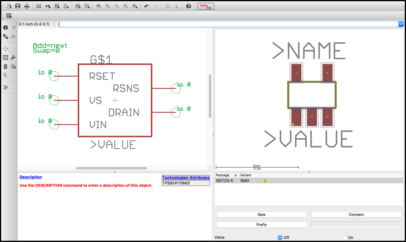
After completing the steps above, you should be looking at the Device Editor, which is where you will link your symbol and package together.
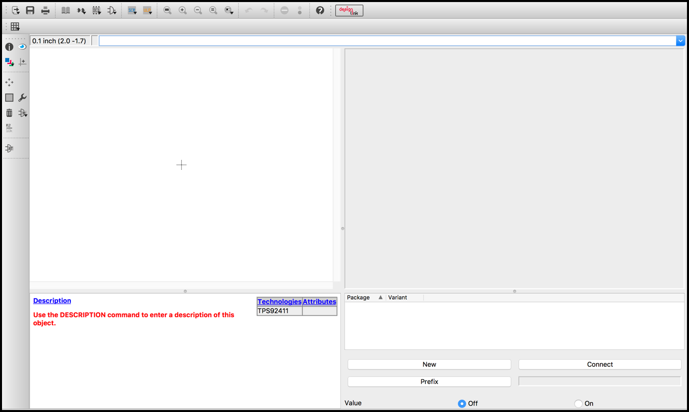
A blank device editor, ready to have your symbol and package added!
Step 2 – Adding Your Symbol and Package
Time to give some love to your lonely device by adding the package and symbol that you made in Library Basics Parts 1 and 2. To make this happen:
Adding Your Symbol
- Select the Add
 icon on the left-hand side of your interface.
 - In the Add Dialog, select the name of your “TPS92411” symbol, then select OK.
- Your symbol will appear in the left panel of the Device Editor. Go ahead drag and left-click to place it on the origin point.
- To finish up, press Esc on your keyboard to get out of symbol placement mode, and then select Cancel on the Add Dialog.
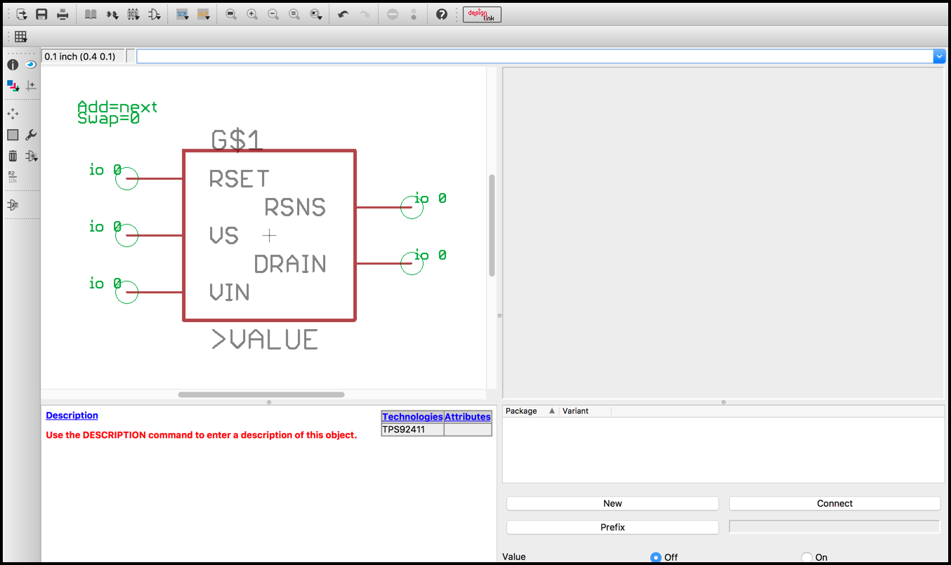
Adding a symbol to your Device Editor will always show up on the left panel.
Adding Your Package
- Select the New button on the bottom-right corner of your Device Editor.
- In the Create new package… Dialog select the name of your “SOT23-5” package.
- Optional: You can add a variant name for your package, which comes in handy if you have multiple packages to add. In our example, we’ll enter “SMD.”
- Select OK, and your package will automatically be placed on the right panel of your Device Editor.
Adding a package to your Device Editor will always show up on the right panel.
Step 3 – Connecting Your Symbol Pins and Package Pads
Now that you have both your symbol and package together, it’s time to let EAGLE know pin to pad connectivity.
Important: Make sure to always double and triple-check your work against your datasheet for every part you make in the future. We already mapped out our connections above from our datasheet, and here they are again:
- RSET → Pad 1
- VS → Pad 2
- VIN → Pad 3
- DRAIN → Pad 4
- RSNS → Pad 5
With this data, let’s get started with connecting them together in your Device Editor:
- Select the Connect button in the bottom-right corner of your Device Editor.
- This opens the Connect Dialog. To begin your connection, first, select a pin in the Pin column, then select a pad in the Pad column.
- Then select the Connect button, and this will move the pin/pad combo over to the Connection column.
- Repeat this process for all of the remaining connections until your Pin and Pad columns are empty.
- Select OK to save your pin and pad connection settings.
No worries if you made a mistake with one of your pin and pad connections. Just choose the connection you goofed on in the Connection column, and then press the Disconnect button to undo the connection. After lining everything up correctly, your Connection Dialog should look like ours.
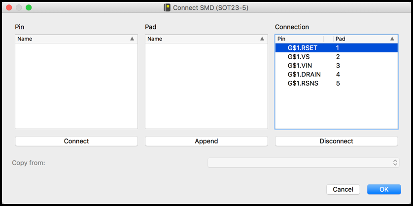
All of our Pins and Pads connected, which shows up in the Connection column.
All of your connections are in place now! Check out the right-hand side of your Device Editor. You’ll know if all your pins and pads are connected if you see a green checkmark next to your package name.
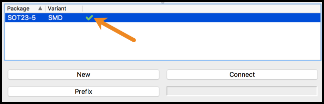
The green checkmark lets you know that all of your pins and pads are connected.
One thing to note is that this checkmark does not mean that Autodesk EAGLE has verified that your connections are accurate. That’s up to you to confirm! All the checkmark means is that you no longer have any pins or symbols that need to be connected.
Adding Those Extra Details
With Step 3 complete, you have now successfully created your first device! There are a few details that we’ll be covering next, but they are entirely optional and up to you if you want to add them. This includes adding a prefix, enabling values, and adding description text.
Adding a Prefix
It’s helpful to add one of the standardized naming prefixes to your devices, such as R for a resistor, or C for a capacitor, and you’ll see these all over schematics and PCB layouts from other engineers. Thankfully there isn’t any guesswork in this process, as there’s already a set of commonly used prefixes for all the parts you’ll run across which are referred to as reference designators. To add a prefix for your device, do the following:
- In your Device Editor, select the Prefix button in the bottom right corner.
- Enter a prefix name in the New prefix: field and select OK. In our example we created a switch, so we will enter “S.”
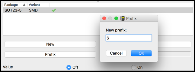
Adding a prefix makes it easy to understand what kind of device you’re working with on a PCB layout and schematic at a glance.
That’s it! Your prefix is now ready to go. When you place this part on your schematic or PCB layout, you’ll notice that the naming convention is S$ following by a unique number to identify each and every unique part on your design.
Enabling Values
Another helpful addition is to allow the editing of the >VALUE text placeholder that you have been adding to your package and symbol. This is turned off by default when you create a new device, and if you leave it this way, then you won’t be able to change >VALUE to anything else when you place your part. This isn’t helpful, so let’s turn it on by simplifying selecting the “On” radio button in the bottom-right corner of your Device Editor.

Set your Value to “On” to make it possible to edit the >VALUE placeholder in your schematic after placing a symbol.
Adding a Description
It’s always good practice to add a description of your device. This can come in handy down the road, especially when you need to find a part with a particular temperature range, supply voltage, or even a vendor part number.
Descriptions in Autodesk EAGLE have the added benefit of being formatted with HTML. This can allow you to bold text, change text sizes, and even create tables! Here’s an HTML Reference Guide to bookmark. And to add your description text, do the following:
- Select the Description link in the bottom-left panel of your Device Editor.
- This will open the Description Dialog. You can enter text and HTML tags in the bottom panel, and the top panel will show you how it will look.
- When you’re all set adding text, select OK to save your changes.
You’ll notice that your Description text has been added below the Description link in your Device Editor, and will also show up when you select your device in your library from the Control Panel.
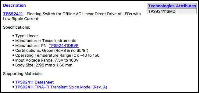
Using the TPS92411 datasheet and Texas Instrument’s website we’ve put together a detailed description of our device.
Land Ho!
You’re done! You have completed your Library Basics voyage and now know how to do many new things, like make a new symbol, package, and device, all in your very own Autodesk EAGLE library. These skills will follow you throughout your journey in electronics design, and you’ll probably find yourself needing to create new parts here and there when you can’t find what you need in the free Autodesk EAGLE libraries.
Let’s take a moment to celebrate by opening your Control Panel and selecting your newly created device. On the right panel, you can see all of the great work you did! There’s the symbol on the left, the package on the right, all nestled together with your description.
Your part family is now complete, congratulations!
Now that you have your own library, are you ready to get your own Autodesk EAGLE Subscription? Subscribe today!