This post is also available in: Deutsch (German)
Our Machining Fundamentals series is created to help you brush up on your CAM knowledge, whether you work in a machine shop or are just getting started. Each episode is hosted by one of our in-house machinists and provides a detailed overview of a tool/process. In the last edition, we covered milling machines. Here we have an introduction to milling tools, where we’ll explore the different types of cutting tools that can be used for milling purposes, when it’s best to use these tools, and how to use them inside of Fusion 360.
In this video, we show two of the more commonly used milling tools: a Flat End Mill and a Ball Nose Mill. Flat End Mills get their name from having a flat bottom all the way across, which then comes at 90 degrees onto our sides. Ball Nose Mills have a radius, a hemisphere, or half of a ball (which is where it gets its name from) to give it a rounded end instead.
Now there is a type of tool that lies somewhere between these two, which can be called a Bull Nose Mill or a Tip Radius End Mill, which has a partly flat bottom with a radius just around the edges. To keep things simple, we’ll focus on our Flat End Mill and our Ball Nose Mill in this video.
So why would we use one of these types of tools over another? It really comes down to a combination of the type of geometry that we’re trying to machine and the stage of the process that we’re at.
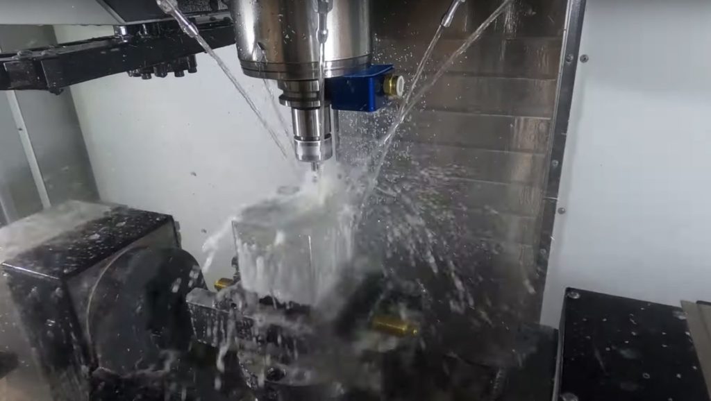
If we look at our Flat End Mill, for example, when we cut away material using this, we’re going to be left with stock that has a flat bottom and straight-sided walls to match the tool’s geometry. This is perfect if the geometry that we’re trying to machine has a flat bottom and straight-sided walls. In this case, we can use a flat end mill to finish our parts to final form.
However, many parts have more complex, curved surfaces. For these, a Flat End Mill is not ideal to use. This is where we now move on to our Ball Nose mill. If we use this tool to cut through the material, again, we will be left with stock that has the geometry of the tool, i.e., the radius or the half ball on the end.
As you can see, when we have multiple passes using the Ball Nose Mill, we’re left with the material in between these, which are called cusps.
We can reduce the size of these cusps by reducing the size of the step over or the passes.
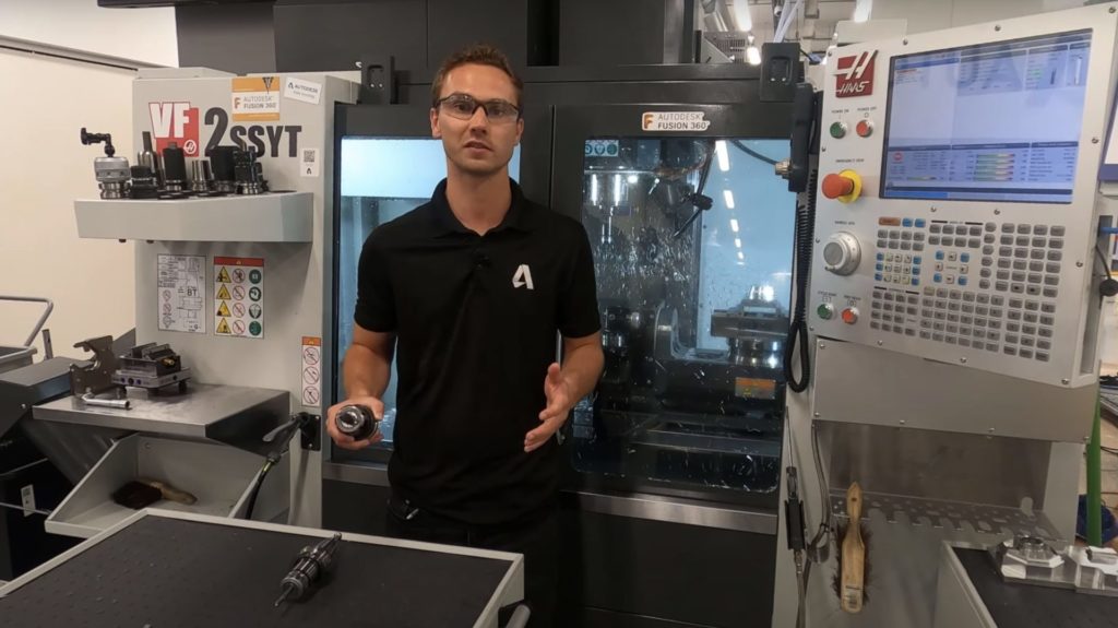
This is a very inefficient way of machining a flat surface like this. Instead, we’d be much better off using a Flat End Mill to quickly clear that material and give us this flat surface.
Where a Ball Nose mill does give us an advantage is when we want to machine a curved surface. If we tried using a Flat End Mill to machine a curved surface, we’d end up with steps that are similar to the cusps created with the Ball Nose. However, on a curved surface like this, it takes much fewer passes with a Ball Nose Mill to reduce these cusps to an acceptable size than it would with a Flat End Mill.
Because of this, Flat End Mills are generally used for roughing when we want to clear the majority of the material away quickly. Whereas Ball Nose Mills are then used for finishing to clean up what the roughing passes have left behind. The exception to this is when we have a flat surface to finish, we can use a Flat End Mill as the geometry of this tool, as it matches the final form of the finished part.
Another choice that can be made with how we cut with our milling tools is whether to use what’s called climb or conventional cutting. These have to do with how the tool rotates in relation to the feed direction and the material that they are cutting away.
Climb cutting rotates the tool so that the teeth digging into the material and the chips have pushed behind the tool as it moves forward. The way that the teeth dig in mean that the tool pulls itself along the material or climbs. Conventional cutting is the opposite direction where the chips of material are pushed in front of the tool as it moves along.
There are a number of factors that will determine which is the best method for a particular application, and that is a whole topic within itself. Generally speaking, climb cutting is preferred, as it leads to lower tool wear and a better quality surface finish.
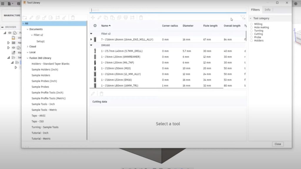
Now that we know a bit more about these tools and when to use them, let’s have a look at how we use them inside of Fusion 360. In the manufacturing workspace of Fusion 360, we have the Tool Library, which is where we can create and store the cutting tools that we’re going to use for a particular job, or perhaps find ones that are always available on our particular machine.
In this document, we can see that there is already a Flat End Mill, and I can create new tools to add in.
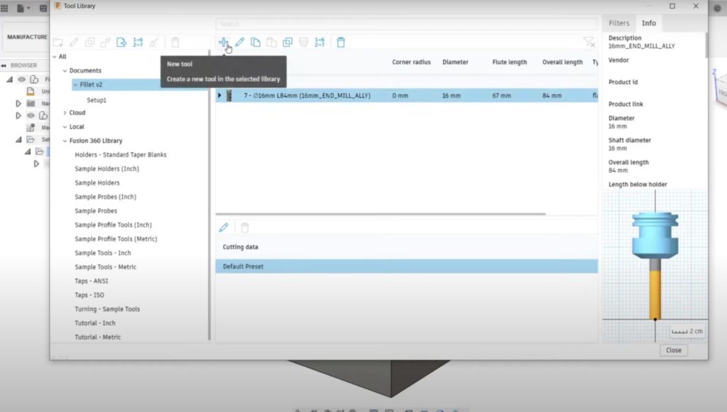

Here we see all of the different types of tools that can be created, including the types we have discussed and many other types—both for milling and for other manufacturing applications. To create a new tool, I need to select the type I want. I will use a Ball End Mill. Now I can fill out all of the necessary information to define this tool.
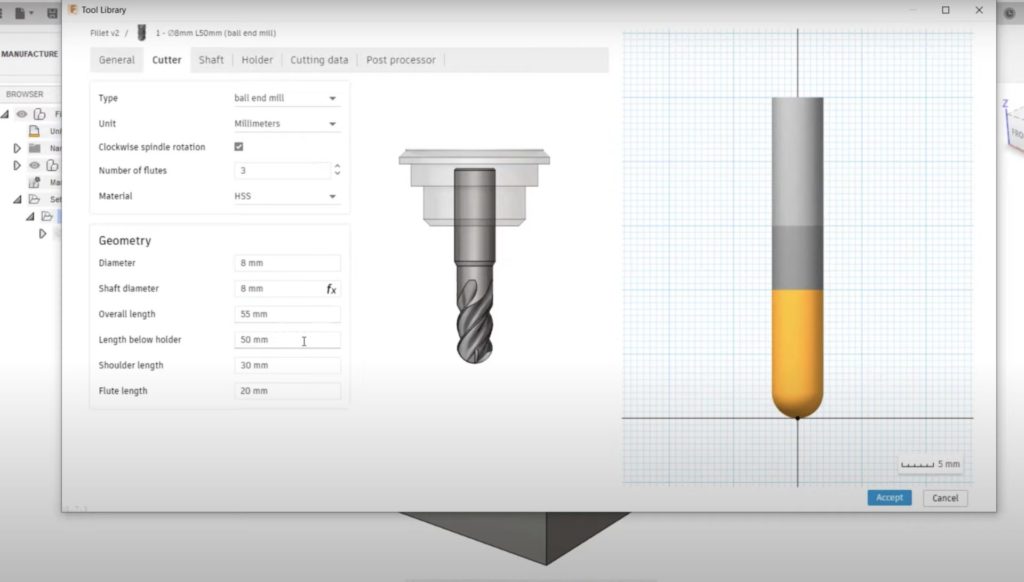
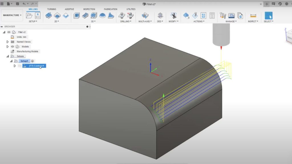
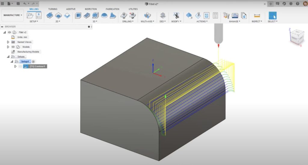
Here we can see a toolpath for machining this fillet, which is currently using a Flat End Mill. But as we’ve already seen, a Ball End Mill would work much better for this type of surface. If i edit this operation in the tool tab, I can now select a new tool from my tool library.
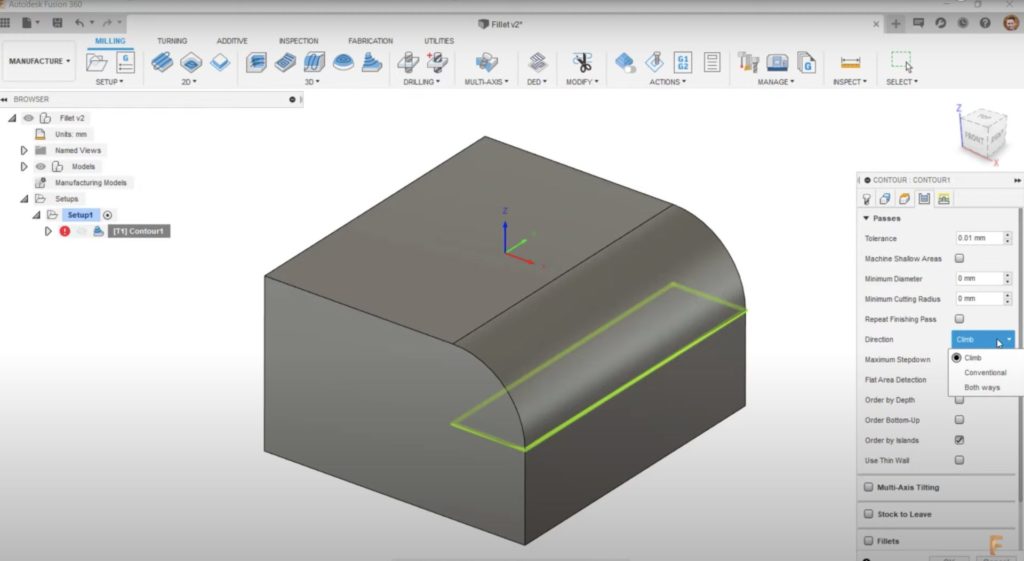
Another change I can make to this operation is in the passes tab, where I can select the direction of cut. This is where I can choose whether the cuts will be climb, conventional, or both ways. There are similar options for many of the other operation types. I’ll leave this one as climb.
Stay tuned: following this episode about milling tools, we’ll be publishing Machining Fundamentals episodes weekly. Future topics include lathes, post processors, toolpath types, NC code, work coordinate systems, and more.
In the meantime, download Fusion 360 to start machining smarter today. Learn more about how to maximize your machine with Fusion 360. Or, refer a friend if you’re already part of our community.
