We created the Machining Fundamentals series to help you brush up on your CAM knowledge, whether you work in a machine shop or are just getting started. In-house machinists at our Birmingham Technology Center host each episode and provide a detailed overview of a tool/process. In the last edition, we covered Work Coordinate System (WCS). Here we introduce speeds and feeds — what they are and how to set your own values in Fusion.
Elevate your design and manufacturing processes with Autodesk Fusion
The phrase speeds and feeds refers to two separate velocities in machine tool practice, cutting speed and feed rate. They are often considered a pair because of their combined effect on the cutting process. Each, however, can also be considered and analyzed in its own right.
To start, we’ll define speeds and feeds. Then we’ll explore why it’s important to get these values right and what happens if we get them wrong. Finally, we’ll look at how you can set your own speeds and feeds values and where we can find that information.
What are speeds?
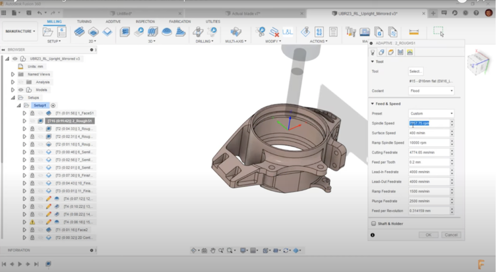
“Speed” refers to surface speed, measured in meters per minute. Surface speed is then converted to revolutions per minute (rpm), which gives us the S code to run on our machine. That gives us the rpm at which our cutting tool will spin. If a milling tool turns once every second, our tool is running at 60 rpm. “Turning” is the opposite, but it’s the same concept—our workpiece turns, and our cutting tool remains stationary.
Autodesk Fusion software contains our main speeds for our cutting spindle and ramp spindle. There are frequently two different speeds for both. A different side of the cut will mean that optimal spindle speeds will differ both for operations ramping and for normal cutting. For example, we may want a faster spindle speed for ramping. But this speed isn’t the best option for our cutting spindle, as this may burn the tool too quickly or provide an undesired surface finish.

What are feeds?

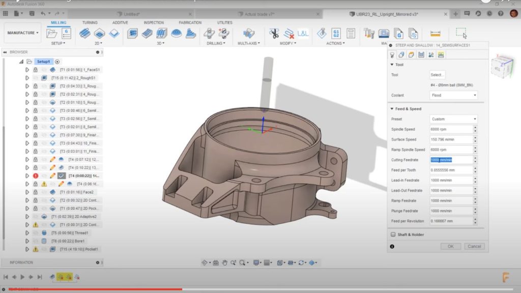
First, let’s look at the cutting feed rate. Our cutting feed rate will take effect when the tool is traveling on the blue toolpath. These are our cutting moves. Our lead-in and lead-out feed rates are the green toolpaths. These feed rates may differ from your cutting feed rate. For example, we might machine a tough material, causing us to worry about chipping or breaking our tool upon entry. We must slow the tool with the lead moves to adjust for this concern.
We also have a ramping feed rate, which is the red toolpath. Just like the lead-in and lead-out feed rates, we may slow the tool for this move because it’s more aggressive and may cause damage. The options for different feed rates are all there so that you can make your toolpath as efficient as possible. The feed rate we set for our ramping may be slower than our cutting feed rate. If we program them to the same value, we may lose valuable cycle time.
Now let’s look at our plunge feed rate. This feed rate determines how fast our tool moves vertically through the air. However, in the case of drilling, this value determines the feed rate at which we drill.
Finally, we have our material removal rate. People frequently underestimate the potential of their cutting tools because they don’t explore them with the manufacturer’s manuals in hand. Dig into your manual; you may be running your cutting tool 30% below its potential. You don’t want to lose valuable cycle time and money—it’s always important to see how far you can push the cutting tools.
Why are speeds and feeds important?
There are several reasons why these values are important. First, they greatly influence a tool’s lifespan. Effects of bad speeds and feeds aren’t as apparent on softer materials (such as aluminum or resin) as they are on harder materials because there’s a wider margin for error. With materials like titanium or Inconel, there’s less room for error. If the values of the feeds and speeds are slightly off, our tool may break more rapidly.
Another reason these values are important is that they affect the surface finish. If we don’t align our speeds and feeds correctly, we won’t get the desired results. If we run our feed rate too fast or our spindle speed too fast, we’ll end up with chatter marks on the surface.
Setting speeds and feeds values
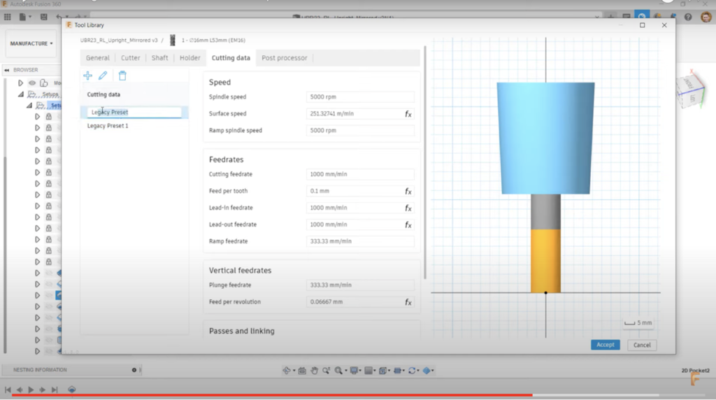
Set your speeds and feeds parameters through operation. You can input individual values into each toolpath. A more efficient way is to use the Cutting Data tab inside the Tool Library. You can store presets to automate the input of your feeds and speeds.

For example, if I use this tool on a few different materials and use it for other operations—such as roughing and finishing—I can create a preset to store the feeds and speeds values for each scenario in Fusion. When it’s time to choose the parameters, I select the desired preset from the drop-down list.
For milling, you need to identify your tool first. With the make and model of the tool, you can find the manufacturer-provided surface speed. The surface speed depends on the tool’s material, the material to be cut, and the operation you’re performing with that tool. When you locate the manufacturer’s recommended surface speed, you can input this speed into Autodesk Fusion, which will give you an rpm.
It’s important to remember the art of the variables involved. Are you using coolant? How far is your tool sticking out? Is your work holding rigid? Consider all of these factors when setting your feeds and speeds. Your feed rate will be determined by your recommended feed per tooth, the amount of cutting edges on your tool, and the rpm. Again, the tool’s manufacturer should provide this information.
Once you’ve input your tool data and appropriate rpm into Autodesk Fusion, you then input your feed per tooth. This will give you a cutting feed rate value, which is the F code used on your machine.
Get started with Autodesk Fusion for a truly integrated CAD/CAM experience.