This post is also available in: Français (French) Italiano (Italian) Deutsch (German) 日本語 (Japanese)
Learn what tool length offsets are, why they’re important, where to find them on your machine, and how to set them.
The Machining Fundamentals series will help you brush up on your CAM knowledge, whether you work in a machine shop or new to machining. In-house machinists at our Birmingham Technology Center host each episode and provide a detailed overview of a tool/process. In the last edition, we covered feeds and speeds. Here we introduce tool length offset—what it is, why they’re important, where to find them on your machine, and how to set them. We’ll also show what can happen when you input the incorrect value.
Elevate your design and manufacturing processes with Autodesk Fusion
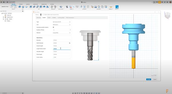
A computer numerical control (CNC) machine stores certain tool information that tells the machinist where to position the tool to cut in the locations calculated by Autodesk Fusion software. Some of this information includes the diameter of the tool, the corner radius (if it has one), and the length of the tool— known as the tool length offset.

What is the tool length offset, and why is it important?
The only known point on the machine is the datum point on the spindle nose. The tool length offset is the difference in length between the spindle nose and the tool’s tip.
If a machinist doesn’t input a tool length offset value, the spindle nose will mistakenly drive to the points defined by the toolpaths in Autodesk Fusion 360. This can break the spindle, damage the machine’s accuracy or alignment, and even force the machinist to scrap machine parts.
Let’s look at two separate holder types: an HSK63 and a BT40. Both fit into various machines and clamp the tool in different ways—but they have different lengths. It’s important to set the offset accurately before using them, as the tool can stick out of the holder by varying amounts.
We use the tool length to offset the spindle nose back by the length of the tool. This ensures that the tool’s tip drives to this new point instead of to the spindle nose.
By letting the machinist set a z-axis datum for each part, the tool length offset enables the CNC machine to compensate for many tools of different lengths. This ultimately enables machinists to use multiple tools without having to reset the z-axis datum every time they use a tool.
Finding the offset
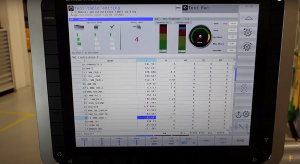
Different controllers store tool values in different places. To access the Tool Length Offset table on the HEIDENHAIN controller—shown in the video above—click on the Tool Library button. There we can view a list of all the tools stored on the machine. To access the Offset table on a Haas NGC controller, press the Offset button.

Setting the tool length offset
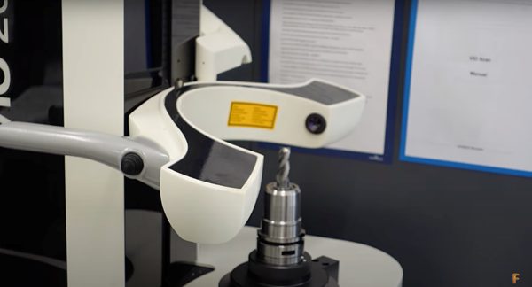
There are many ways to set the offset. The video features a machine that has three tool-setting options: a laser tool setter, a mechanical tool setter, and a slip gauge with a known calibration tool. You can also set the tool off the machine using specialized tools like an optical tool setter.


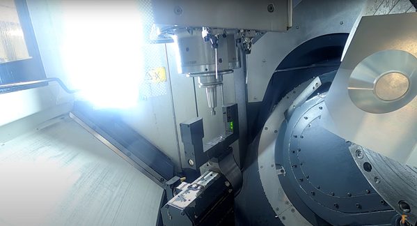
The video shows a machine using a laser tool setter, which doesn’t need a manual setup. However, a Haas machine uses a mechanical tool setter, which does require a manual setup. Each type of tool setter has its advantages, and both typically deliver accurate and consistent results.
Optical tool setters are useful on routers and machines that don’t have their own toolset equipment. These tool setters are often highly accurate, but they require manual input into the controller. The least accurate are slip gauges, which can be used on all CNC machines, and require manual input into the controller. Newer machines rarely incorporate this approach.
Incorrect tool length offset value
As we simulate our toolpaths in Autodesk Fusion, it’s important to check that the corresponding offset values are set within the Fusion Tool Library. This ensures that the simulation and the NC output are accurate.
The video shows a model with various surfaces machined at different angles. All surfaces appear smooth without any blend issues between the surfaces. Let’s see what happens when we adjust the offset of the tool by -0.5 mm. Now thinking the tool is shorter than it actually is, the controller pushes the tool further into the part by 0.5 mm.

Clearly, the proper offset is crucial to getting the correct finish required on machine parts. Get started with Autodesk Fusion for a truly integrated CAD/CAM experience.