We created the Machining Fundamentals series to help you brush up on your CAM knowledge, whether you work in a machine shop or are just getting started. In-house machinists at our Birmingham Technology Center host each episode and provide a detailed overview of a tool/process. In the last edition, we covered post processors. Here we have an introduction to toolpaths, where you’ll get an in-depth look at various toolpath types, from 2D to 5-axis, and how you can program them with Fusion 360.
You’ve probably heard toolpaths being spoken about in terms of 2D, 3D, and full 5-axis simultaneous. But what do these terms mean? In this article, we’ll explain exactly that, along with how we can program these toolpaths inside of Fusion 360.
What are 2D Toolpaths?
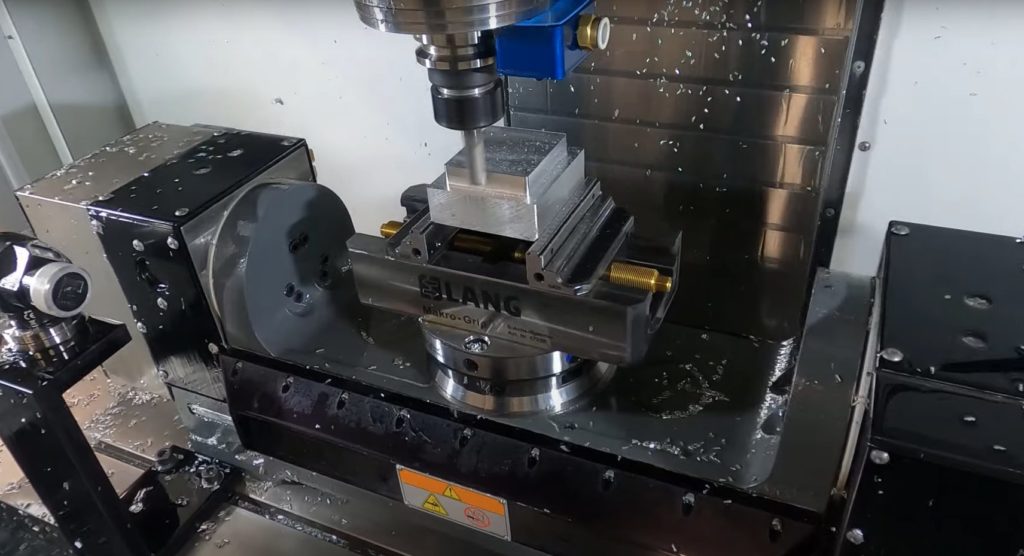
The most basic toolpath type is 2D. As its name suggests, 2D toolpaths only ever move in two dimensions, or two of the machine’s axes, while cutting. Generally, these are the x and y axes. If we look at our machine in the video above, we can see a 2D toolpath in action. You can see the tool does come down on the z-axis, but when the actual cutting pass begins, the tool only moves on the flat x y plane.
What are 2.5D Toolpaths?

The next step up from 2D toolpaths are 2.5D toolpaths. 2.5D toolpaths are when we take a 2D pass and add multiple depths to it. The reason why they’re called 2.5D and not 3D is because the tool is still only ever moving in two axes. We have a 2D pass, the tool steps up or down in zed, and then that same 2D path is repeated.
What Are 3D Toolpaths?
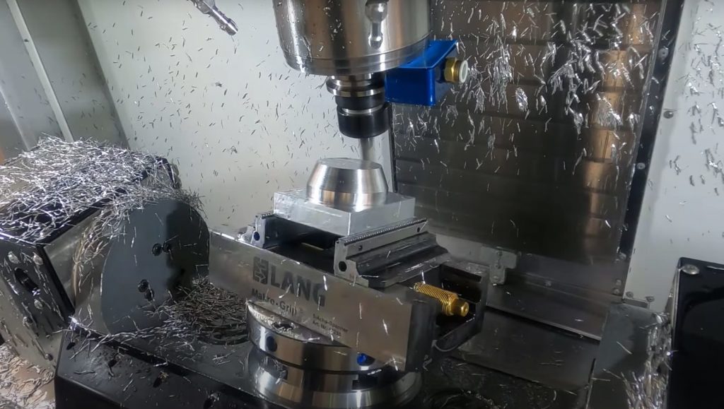
The next type of toolpath is a 3D toolpath. This time, we have all three axes moving to our x, y, and z axes while cutting material. We can now create more complex geometry, such as curved surfaces. In the video above, you can see a 3D toolpath in action while a ramp tool creates a fillet. The tool moves in the x and y directions while continuously moving down in zed.
At this stage, we’re already using all three linear axes. So the next step is to introduce a rotational axis. Now, this is only possible depending on the available setup of your machine. Some machines only have three linear axes, meaning that anything more than a 3-axis toolpath is impossible. Some machines have one additional rotational axis, and others like the one used in the video above have two additional rotational axes. For more information, make sure to watch the Machining Fundamentals video on milling machines.
What Are 5-Axis Toolpaths?

As my machine has two rotational axes, I can go above a 3-axis toolpath. One option is to use a 4-axis toolpath, which, as you might guess, uses my three linear axes and introduces one rotational axis. This option will give me greater access to areas on the parts with my cutting tool because I can now rotate my parts relative to the tool. The next stage is to go for a 5-axis toolpath, which uses my three linear axes and two rotational axes. This option gives me even greater access again because I can use a combination of the rotational axes to gain access to even more areas. I can also control the angle at which my tool makes contact with the parts, meaning I can influence the surface finish quality.
What Are 3+2 Toolpaths?
One more term that you may have heard is a 3+2 toolpath. You might be wondering why this isn’t the same as a 5-axis toolpath. The main difference comes down to how many axes can move while the part is getting cut. For a 5-axis toolpath, all five axes can move as the part is being cut. But for a 3+2 toolpath, you use rotational axes to reposition the part relative to the tool while away from the material. Once the rotational axes reposition the part, the toolpath runs the same as any other 2D or 3D toolpath.
In the video, you can see an example of a 3+2 toolpath in action. You’ll notice a standard 2D toolpath cutting the part. The tool moves away, and the rotational axes reposition the part, and then the tool comes back down onto the part and machines in 3-axis. Using the rotational axes for positioning on the toolpath and the nature of the toolpath itself makes this a 3+2 toolpath.
Taking This Knowledge to Fusion 360
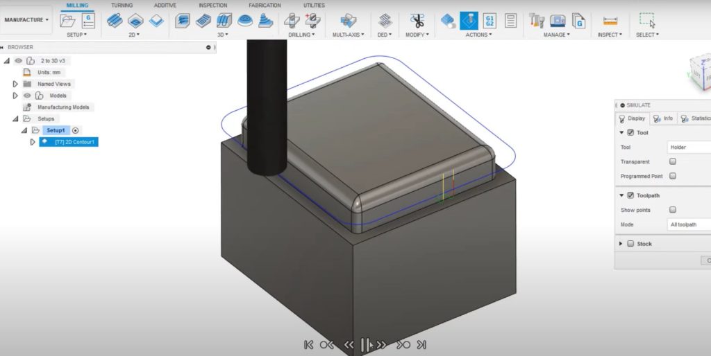
Now that we understand the different types of toolpaths, let’s look inside Fusion 360 to see how we can program them. Fusion 360 splits the toolpath strategies for milling into 2D, 3D, and multi-axis. Here we can see a 2D profile path applied, only occurring in the x and y directions. If I edit this, I can add multiple depths and can convert it to a 2.5D toolpath.

From my 3D strategies list, I have a ramp toolpath, which moves the toolpath in the x, y, and z axes at the same time while running. Moving to the multi-axis options, I have a rotary toolpath, which is a 4-axis toolpath that uses one rotary axis. I also have a swarf, which is a full 5-axis simultaneous path. You’ll remember that we also discussed 3+2 toolpaths, which are when we use rotational axes but only for positioning. Using tool orientation, I can turn any of the toolpaths from their 2- or 3-axis version into a 3+2 toolpath. I need to turn this option on in the geometry tab by setting my new axis directions from the card. Then, everything else about programming the toolpath is the same.
More Machining Fundamentals Coming Soon
Stay tuned: following this episode about milling tools, we’ll be publishing Machining Fundamentals episodes weekly. Future topics include NC code, work coordinate systems, and more. Check out the rest fo the Machining Fundamentals videos below:
Machining Fundamentals: Introduction to Milling Machines
Machining Fundamentals: Introduction to Milling Tools
Machining Fundamentals: Introduction to Lathes
Machining Fundamentals: Introduction to Post Processors
In the meantime, download Fusion 360 to start machining smarter today. Learn more about how to maximize your machine with Fusion 360 here.

