I’ve been using a combination of Fusion 360 and PowerMill for a little while now, and while PowerMill is still more familiar to me, most of the time Fusion 360 serves my needs superbly. Fusion 360 has just recently introduced additional functionality through the manufacturing extension, including Steep and Shallow and Surface Inspection. I took those tools for a spin to machine this mudguard tooling on a Hermle machining center in our Birmingham Technology Center in the UK. Watch the video below to see the full process and how the manufacturing extension helped me achieve a high-quality finish on the final part.
Steep and Shallow
The manufacturing extension includes several new manufacturing tools, but I want to focus on Steep and Shallow and Surface Inspection. I particularly want to focus on the benefits of using them in your manufacturing process. Steep and Shallow is a new 3D finishing toolpath that some of you may recognize from PowerMill. In fact, Steep and Shallow is PowerMill’s 3rd most used CAM strategy. Steep and Shallow automatically recognizes the steep and shallow regions on freeform geometry, optimizing the toolpath for each region and combining them to produce a single toolpath.
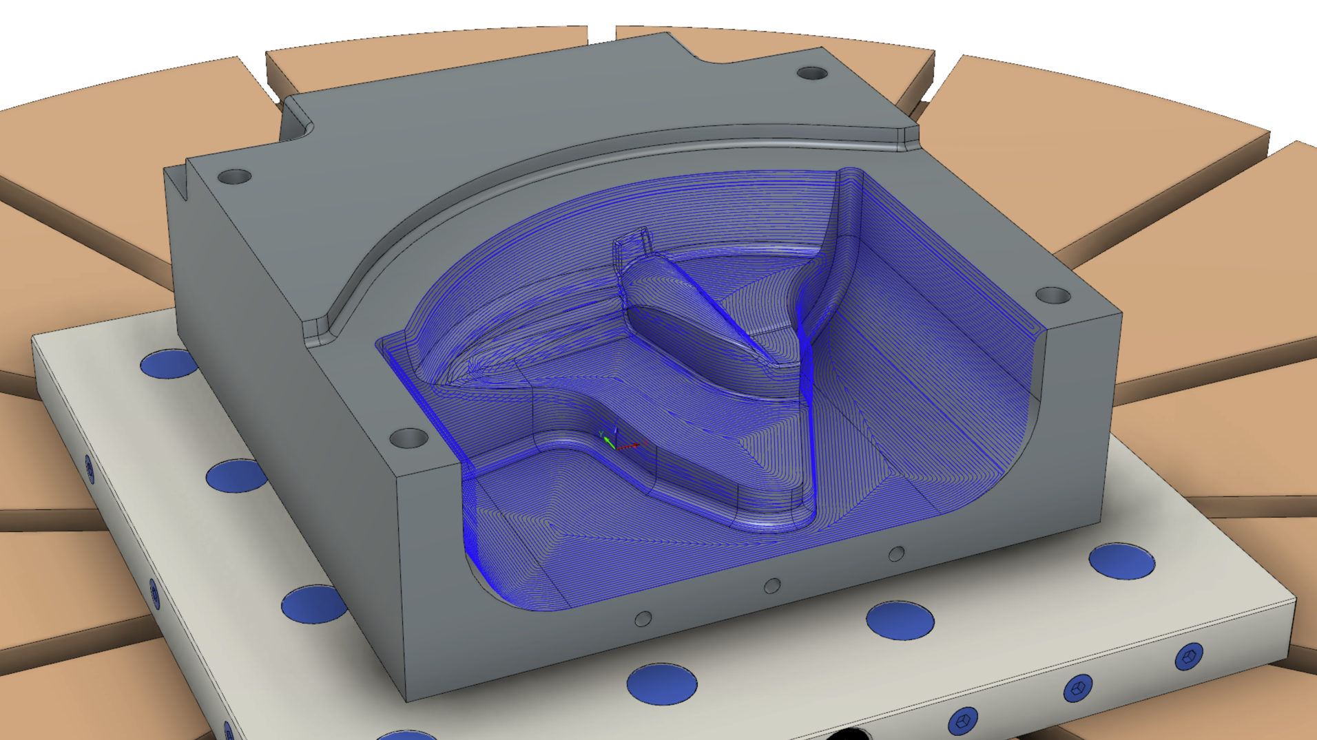
On its face, this seems like a pretty simple task. It also seems achievable by manually combining two separate strategies, which is exactly what I did before. When machining shallow areas on a part I would always tend to use one of the following toolpaths: where fillets where present I would likely use a Scallop style strategy; where no fillets were present (i.e. sharp corners at the base of a pocket) I would tend to use a Parallel strategy. When machining the steeper areas of the part, Contour was always in my kit bag. Contour steps down steeper areas and ultimately gives me a decent quality toolpath for areas such as pure vertical walls.
Steep & Shallow combines these individual toolpaths into a single compounded strategy, and I discovered several additional benefits along the way.
Continuous Spiral for Improved Surface Finish
When using Scallop option on shallow areas, the new Steep and Shallow strategy has the option to use continuous spiral. This means the tool does not have to perform a transition move between passes on shallow regions. A minor benefit is reducing cycle time with less overall moves. But the biggest benefit here is that with no steps between passes, there are no marks where the tool transitions between passes.
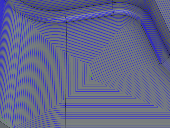
Normal Scallop with separate passes
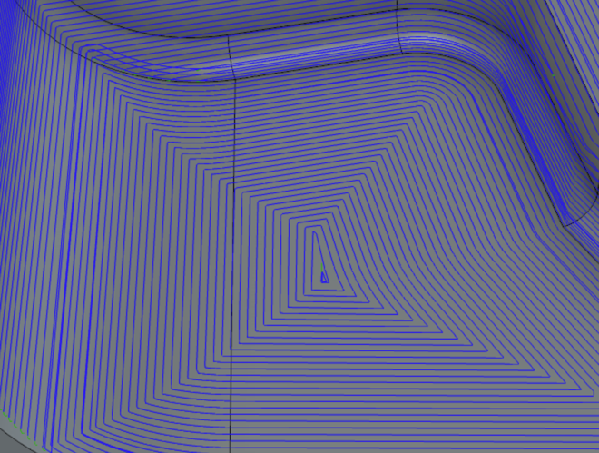
Continuous Scallop with no seam between passes.
Corner Smoothing and Automatic Cusp Removal
Notice that our new Steep and Shallow toolpath contains no sharp corners at all. The Smooth Offsets option rounds the sharp corners from the toolpath, which has two major benefits. Generally speaking, the machine tool control is almost always looking ahead while executing a toolpath. When the control sees a sharp corner coming up in a toolpath, it automatically reduces the programmed feedrate so the cutting tool can change direction at the sharp corner. This does two things. First, when the feedrate slows down, the cutting tool stops deflecting which can result in a dwell mark on the part. Second, when feedrate reduces automatically, machining cycle time increases. Eliminating all sharp corners from the toolpath smooths out machine motion, making the machining cycle time faster and improving surface finish.

Normal Scallop with separate passes
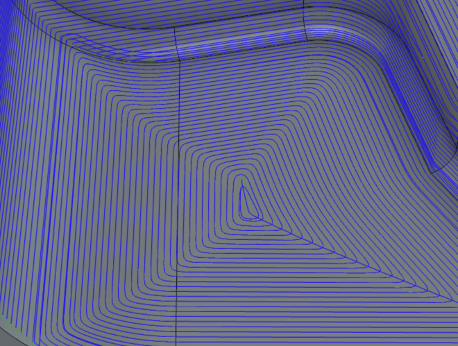
Scallop with Smooth Offsets and Remove Cusps and Junctions enabled.
Also, notice that there is a centreline (centerline, for those of you in the US) trace as the final cutting action in the Steep and Shallow toolpath. The centreline cut passes over all of the corners to remove the tiny cusp of material left where the cutting tool smoothly changed direction on the scallop toolpath. The increased distance between the passes at the corner means the cusp is slightly taller, and this final pass reduces those remaining cusps, again improving final surface finish quality.
Wall Clearance with Parallel
We’ve taken a look at several benefits associated with using a Scallop to machine shallow areas — but what about Parallel? As we mill the bottom of this deep pocket, shown in the screenshot below, the tool approaches the side wall at the end of each pass. With a traditional Parallel, this may cause an issue as the tool could engage with the wall of the pocket. That engagement creates a mark on the finished surface and may cause significant wear or damage to the tool.
The new Steep and Shallow toolpath strategy automatically detects walls and includes a Wall Clearance parameter that ends the parallel passes slightly short of the steep wall by the entered distance. This helps avoid the tool touching the wall of the pocket, resulting in a better surface finish especially on the steep faces of the part.
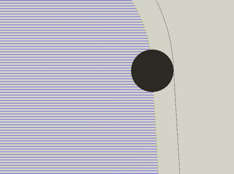
Parallel Passes with no Wall Clearance
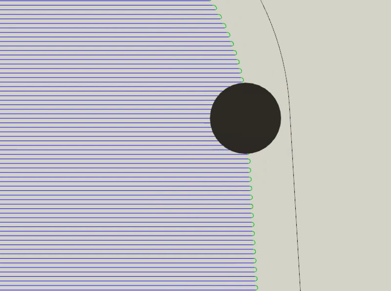
Parallel passes with Wall Clearance
Automatic Parallel Angle
Another benefit to the Parallel shallow strategy in Steep and Shallow is automatic angle calculation. This adjusts the angle of the parallel passes based on each individual region of the part geometry. The angle calculates automatically to reduce toolpath length, resulting in more efficient machining and reduced cycle times.
To revert to a consistent pass angle, check the “Fixed Angle” checkbox and all the Parallel passes will go at the specified direction, which is set relative to the X-axis of the work coordinate system.
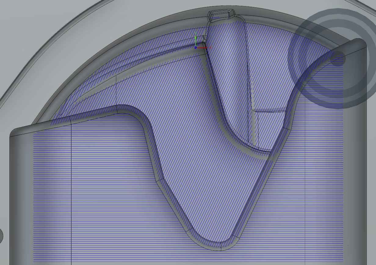
Automatic Parallel pass direction
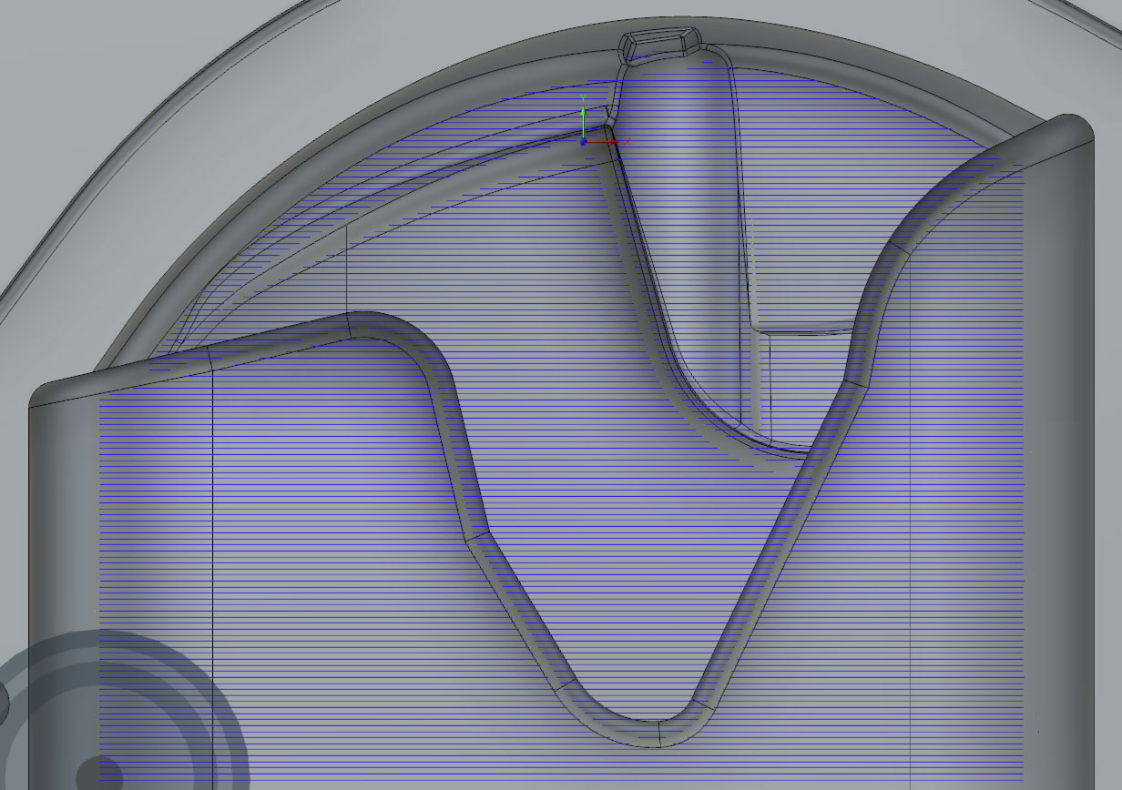
Fixed Parallel pass direction
Constant Overlap Between Steep and Shallow Regions
When combining two separate strategies like Parallel and Contour, reducing seams to blend the steep and shallow regions together was always a bit of a guess and check game. Now, Steep and Shallow includes a built-in overlap value, which overlaps the strategies used on the steep and shallow regions by the given amount. Without the overlap value, the toolpaths for the steep regions and the toolpaths for the shallow regions step over at exactly the same edge. This can result in small misalignment, creating a seam on the surface finish of the machined component. By entering an overlap value, the boundary expands slightly so the steep and shallow regions step over in different locations, minimizing dwell marks.

Surface Inspection
Now that the part has been finished, or even semi-finished, it needs to be inspected to understand how accurately it has been machined. In-process inspection of a part is extremely useful in determining how much material is left on the part after a semi-finishing operation. This information helps drive decisions like making adjustments to the tool offsets or toolpath itself. Inspection is also valuable after the final finishing passes to determine whether the part is in tolerance, needs re-machining, or has too much material removed. The results help with valuable downstream decision-making before removing the part from the machine, and accurate re-machining becomes much more difficult.
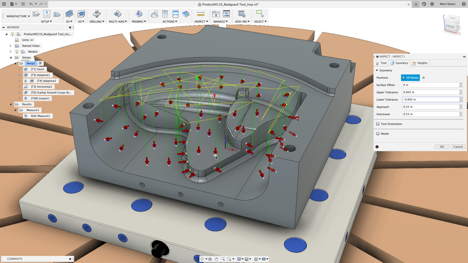
With Surface Inspection, I can select the critical locations on the original CAD model where I want the probe to check the in process machined part. Selecting these points on the CAD model tells Fusion 360 where to probe. Fusion 360 compares the point measurement captured by the probe on the machine tool to the expected position of point on the CAD model. Using those results Fusion 360 can tell me if the probed location is high (meaning there is additional material on the part to be removed), low (meaning that maybe we’ve machined away too much material and so we have a problem), or is within tolerance (meaning that we may not need to perform any more machining operations on that region of the model).
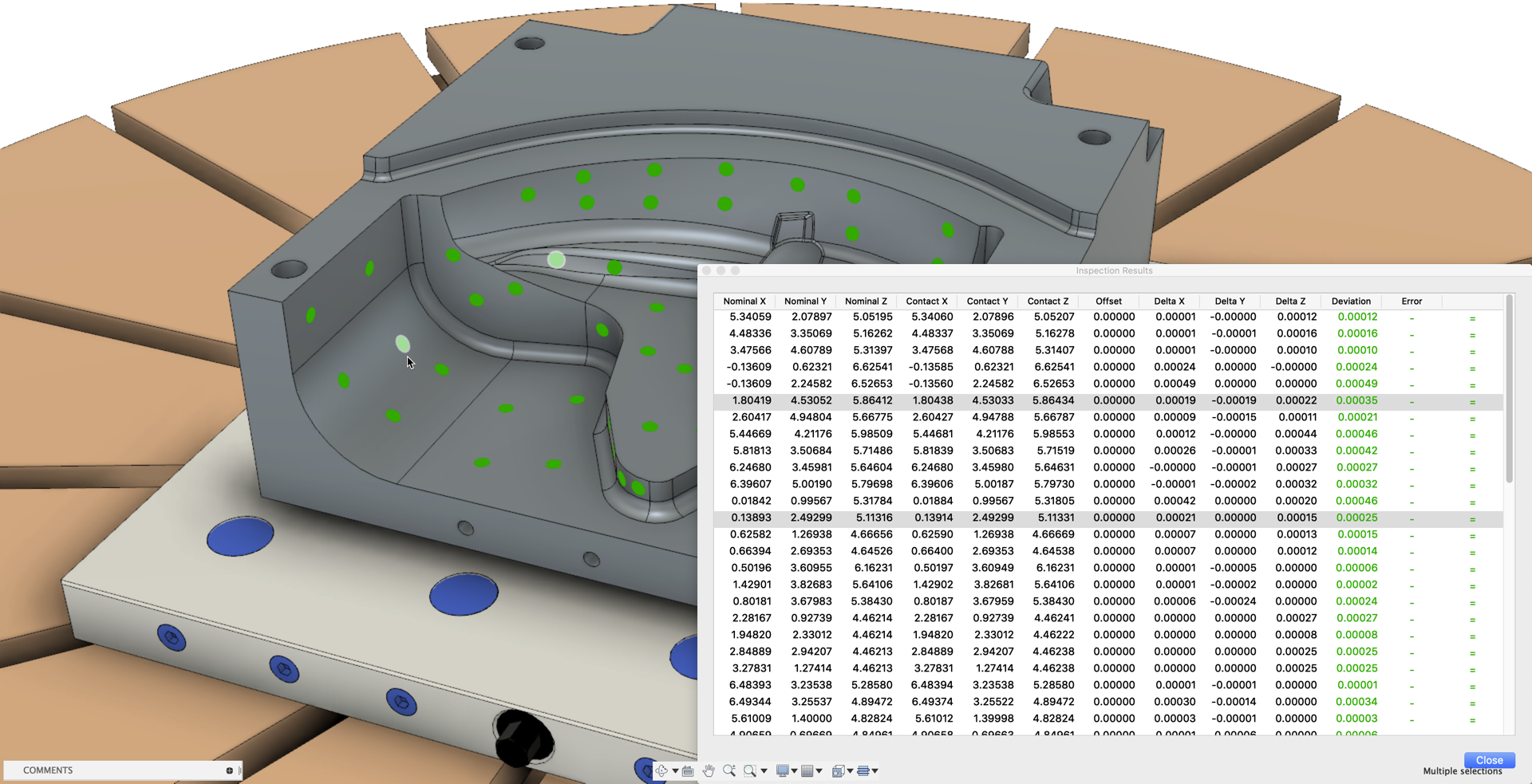
Surface Inspection Results
Fusion 360 displays the results of the in-process probing operation in two ways: on the part as colorful dots where green indicates within tolerance, red is remaining material, and blue is less material than expected, and in the results window. These results allow us to make very important production decisions before we continue to manufacture the part. For example, if the results show there is less material on the part than required, we can decide to scrap the part before investing additional time and resources. Alternatively, if there is less material than expected but there is still material to be removed – so the part is not scrapped, but is also different than expected – we can check the accuracy of the setup and make any necessary adjustments before we continue machining.
Surface Inspection, like any probing functionality, requires a post processor that supports it. As all of our post processors are open-source, you are welcome to make these edits yourself. If you feel comfortable doing so, that is. Check out the Services Marketplace to connect with a partner for paid post customizations.
Ready to give the manufacturing tools in Fusion 360 a spin? Check out more details on the manufacturing extension here
Want to try Fusion 360? Download a free trial today.