The hole recognition strategy available in the Fusion 360 Machining Extension automates the process of creating hole machining operations. This gives you the ability to evaluate multiple holes sizes to determine the best type of drilling operation to apply.
Regardless of whether you’re machining a simple bracket, or programming a complex injection mold core block, chances are you regularly need to produce NC code to machine holes – probably lots of them. The act of drilling a hole into a part is arguably one of the simplest things your CNC machine is ever going to do. Programming the holes, however, can be a very repetitive and time-consuming task.
Let’s get started
Using this mold core block, we’ll discuss the hole recognition capabilities inside the Fusion 360 Machining Extension. We’ll also explain how they can help automate one of the most common programming tasks in your CNC machine shop.
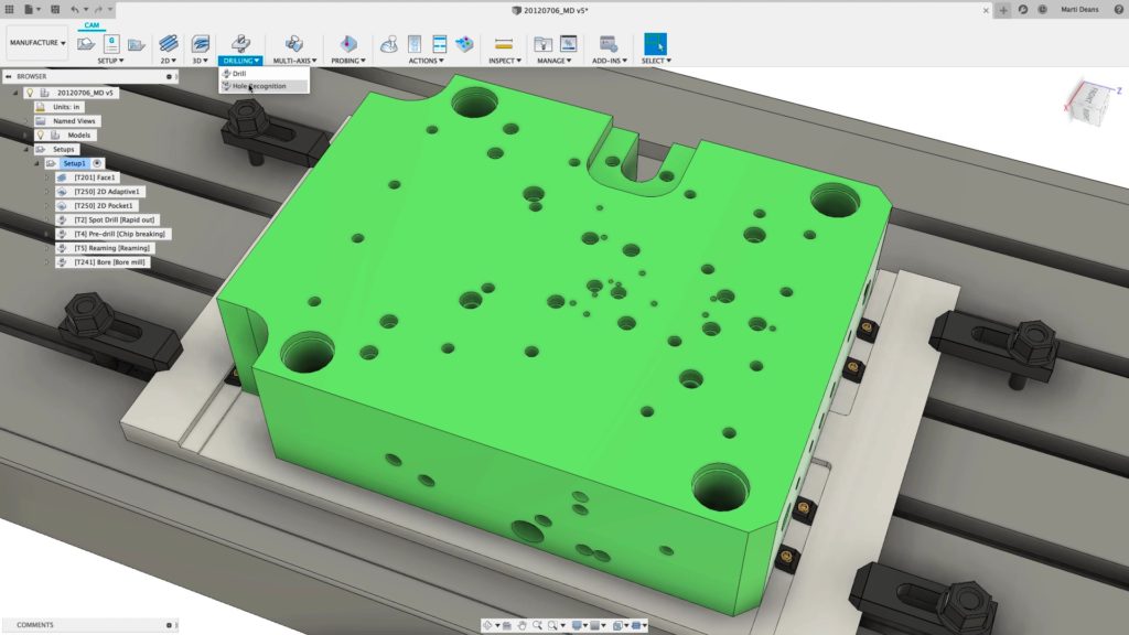
You can see that this part contains a mixture of hole sizes, hole types, and hole orientations. You can produce some with a simple drilling cycle. Others are more complex, requiring combinations of drilling, tapping, and counterboring. Many holes align with the Z-axis of the machine, but there are also holes that align with the X and Y axes.
The point here is that while a hole is a simple piece of geometry, parts can often include a plethora of different hole combinations. It’s this, the almost unlimited combination of hole types, that makes programming them a real challenge. Specifically when dealing with parts containing many hundreds, or even thousands, of holes.
Hole drilling – it all begins with feature recognition
When programming parts with multiple hole configurations, use hole recognition. The customary way of programming these parts is to create an operation for each section of the hole> For instance, if you think of a tapped hole, you would typically create three drilling operations – spot drill, tap drill, and tap.
You would then need to repeat these same operations for other sizes of tapped holes on your part. If you have three sizes of tapped holes, you’ll need to create nine operations to complete the programming of all the holes.
Hole recognition allows you to create general hole-making templates that define the way you want to machine a hole, then use those templates to recognize hole groups. Once you’ve selected that template as your drilling action, hole recognition will create the operations to machine the selected holes, pick appropriate tools from a selected tool library, and re-order operations to minimize tool changes.
The hole drilling commands are accessible via the Hole Recognition option, located under the Drilling drop-down menu.
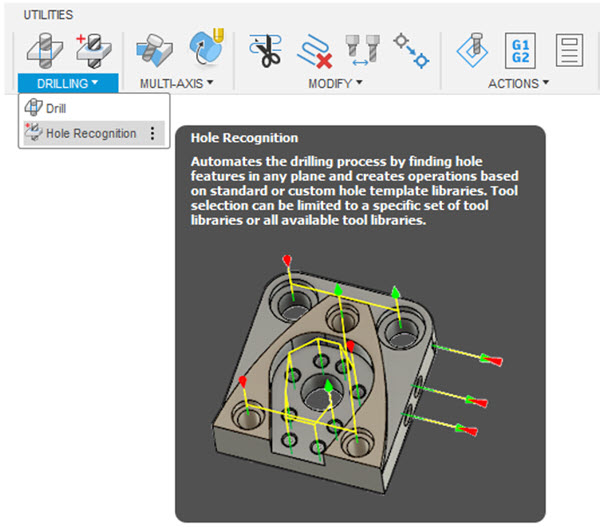
When you trigger the hole recognition command, Fusion 360 analyzes the CAD model and identifies any cylindrical/conical holes. Once the analysis is complete, a new menu displays to offer additional control of the drilling process.
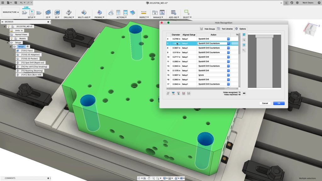
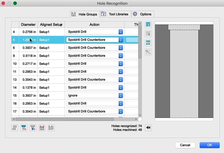
This menu displays a list of the identified holes in the “Hole Groups” tab. It also displays additional information about the hole(s) such as the dimensions and machining setup. A fly-out menu displays an additional visualization of the individual elements that make up the hole. The interactive display helps here – as you select the hold groups in the menu, the relevant parts of the model change color.
By default, any holes with the same dimensions will automatically group together. This helps optimize the subsequent drilling toolpaths. You can machine the group as a whole, and not as separate features.
What’s next?
The next step is to decide what to do with the identified holes. Here, we can choose an appropriate “Action” from a simple drop-down menu. Fusion 360 comes pre-loaded with some standard options including “Simple Drill”, “Countersink Drill”, and “Ignore”. The expectation is that users build their own library of actions to define how to machine specific hole types. You can save these templates to a library to use on future projects for major time savings.
The Hole Groups menu also provides additional controls, such as the ability to:
• Add/remove holes to/from the calculation
• Explode hole groups – Converts the hole group into separate holes
• Delete top segment – Removes the top segment from a multi-cylinder, concentric hole
• Delete bottom segment – Removes the bottom segment from a multi-cylinder, concentric hole
• Split hole signature – Divides a thru-hole into 2 pieces, used when machining from opposite sides
• Flip hole – Changes the machining plane to the opposite side
Choosing the right tool for the job
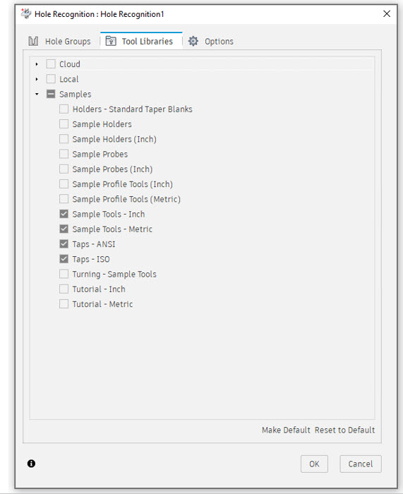
Once you select the appropriate actions, it’s necessary to decide which cutting tools to use. This is a simple case of selecting the “Tool Libraries” tab and activating your preferred tool library. Fusion 360 will then choose the most appropriate cutting tool based on some key tool-specific settings.
Those new to Fusion 360 will appreciate the fact that it comes pre-loaded with a number of standard libraries. Of course, the real beauty here is the ability for you to build your own library containing your favorite tools.
Advanced manufacturing options that make a big difference
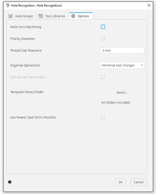
Before we look at the toolpaths that Fusion 360 creates, it’s worth discussing some of the more advanced settings that are accessible via the “Options” tab. These really can make a big difference to machine utilization and overall machining cycle times.
Hide and ignore hole groups not aligned with this setup
When active, this option limits the hole search process to identify only those holes that can be drilled using 3-axis machining in the plane of the active setup. In this example, switching this option on means that the holes on the side wall of the part are ignored.
Switching this option off results in Fusion 360 producing toolpaths for all holes in all orientations.
Minimize tool changes
Switching this option on changes the order of the toolpaths to minimize the number of tool changes. If you are using the same tool on two different hole groups, those groups should be output consecutively to have the desired effect. Deactivating this option causes Fusion 360 to group machining operations by hole. Note this option is only available when “Organize each group’s operations inside a folder” is off.
Organize each hold group’s operations inside a folder
When activated, this setting creates additional folders with names that match the name of the hole groups and then places the resulting toolpaths in these folders. This option is only available when you deactivate the “Minimize Tool Changes” option.
Hide and ignore groups with diameters greater than:
As the name suggests, this option provides additional control over the size of holes that Fusion 360 will identify and machine. Any holes with a diameter larger than the value you define will be ignored
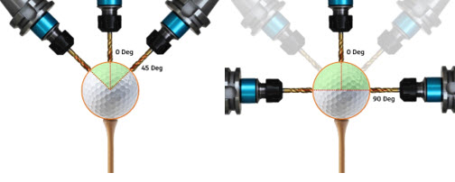
Show only groups with an angle between:
This option can be used to limit the machining of holes, based on the angle of the hole relative to the plane of the active Setup. The option uses “Minimum” and “Maximum” angular values to prevent holes from being machined.
As an example, think about a golf ball sat on a golf tee. Let’s imagine that each dimple on the ball represents a hole that needs to be drilled into the ball. If we entered a minimum value of 0, and a maximum value of 45, we are limiting the machining to the top 45 degrees of the ball. If we changed the maximum value to 90 degrees, we are effectively allowing the entire top hemisphere of dimples to be machined.
Template directory
Allows users to select the location of their preferred hole group template file.
And now the magic happens
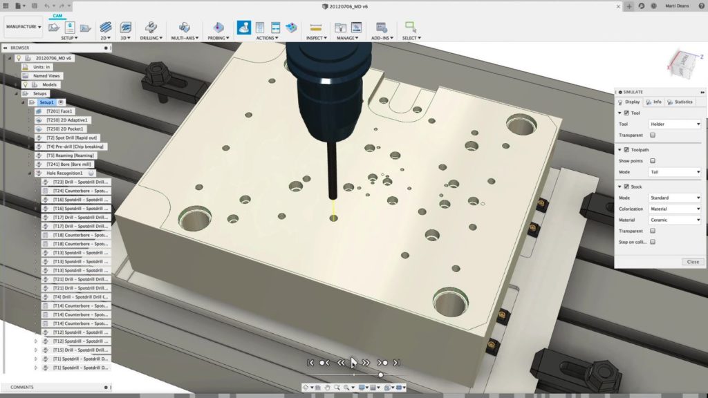
Once you define the appropriate options, just click “OK”. Fusion 360 chooses appropriate tools for the holes and calculates a series of named toolpaths. These are in the appropriate folders within the browser.
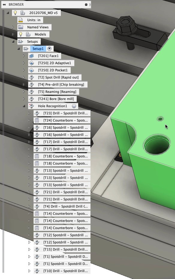
It’s now a simple case of simulating the toolpaths to confirm all is well, before outputting them as post-processed G-code to run on your CNC machine tool.
Give the Fusion 360 Machining Extension a Try for Free
The addition of Hole Recognition to the Fusion 360 Machining Extension, will greatly reduce the time and effort you need to program holes on parts. Automating the identification of families of similar hole types and subsequent toolpath calculation should convert this traditionally tedious process into big productivity gains.
Give it a try today in Fusion 360. Visit the Fusion 360 online help site for more details about the Machining Extension.
