v.2.05519
- We fixed an issue some legacy designs that were causing the CPU so scared that it jump to 300%, which was just outrageous.
- Apparently if you tried to invoke the Promote command in the Results panel of the tool in Simulation after you have solved for a Shape Optimization study, nothing happened. Not even a dialog showed up. This was bad behavior, so we corrected it.
- If you were in a Team Hub and wanted to open a 2D drawing saved in the team hub project from File > Open, Fusion 360 disagreed with your action and locked up the UI so you can no longer interact with it. Not cool. After a stern talking to, you should now be able to open 2D drawings in a Team hub just fine.
- We dropped a new CAM kernel for the Manufacture workspace, and has fixed the 2D contour issue where the tool-path with Both Ways and Roughing Passes settings were wrong.
- Sfivaz reported that the tool entry position option for 2D Chamfer was missing after the March update. We quickly traced the issue back to a regression that had occurred, so we brought it back in tip-top shape.
- Dezeray told us about how her 3D pocketing tool-path wasn’t work properly. This was related to having Both Ways was selected, which resulted in an Empty Tool-path warning. This is now fixed and her pocketing tool-path should work as it should.
March 13, 2019 Product Update – What’s New
V. 2.0.5511

[icon name=”check” class=”” unprefixed_class=””] Bend command bug fixed – after our latest update, eellenburg promptly found an issue where the inside bend radius was causing a flange to be shorter when it is bent from the inside. We’ve quickly go to the bottom of this and got it sorted out.
[icon name=”check” class=”” unprefixed_class=””] Unresolved Components issues fixed – Big_Mak tried to open an older assembly he made in Fusion 360 and was unexpectedly greeted with an error message say “This document contains unresolved components”. Sorry about the hiccup here, it’s all fixed now.
March 11, 2019 Product Update – What’s New
V.2.0.5508
[toc]
Usability
[icon name=”gift” class=”” unprefixed_class=””] New! Know when a teammate is working on your design at the same time
Working together on a team is great, but when your work is over-ridden by someone else’s work without you even knowing (until it’s too late) can be a huge setback. Previously there wasn’t any way to know who’s working on the same design as you are. Now there is!

We’ve instrumented some new tech that lets you know when your teammate is working on the same design by displaying an user icon in the quick access toolbar. Hovering over it will show a tooltip of who is working on it. The design item in the data panel will also show a banner that the same design is in use by one of your team members.
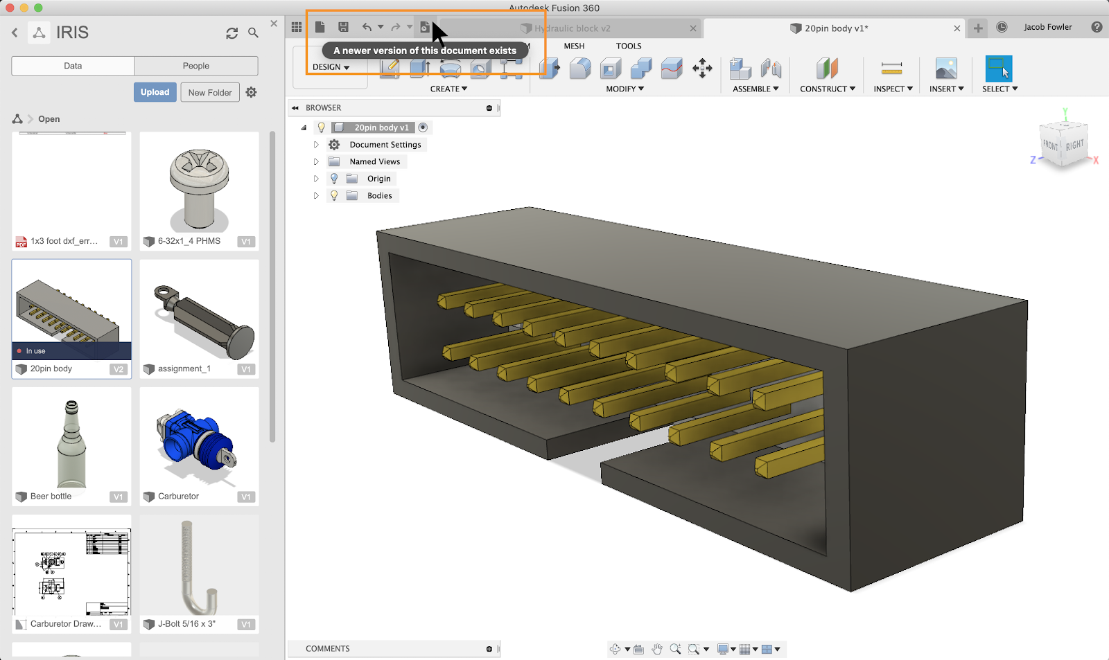
In this example, if Phil made a change to the design and saved it, the icon in the toolbar will change, letting you know that this design now has a newer version.
Note that this functionality is currently only available if you’re on a Team Hub. We are still refining the experience and will be releasing it to a broader group once we have everything buttoned down.
[icon name=”gift” class=”” unprefixed_class=””] New! A more modern toolbar
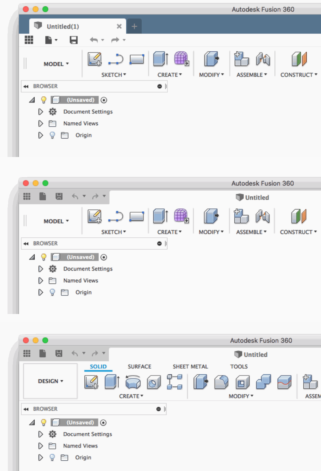
Based on the feedback we’ve gathered from you, we’ve updated our toolbar to be less distracting and more considerate of your design canvas space. The Fusion 360 toolbar is now sporting a more neutral color palette and has quick access tools and document tabs all in line with each other, giving you more space to view your designs.
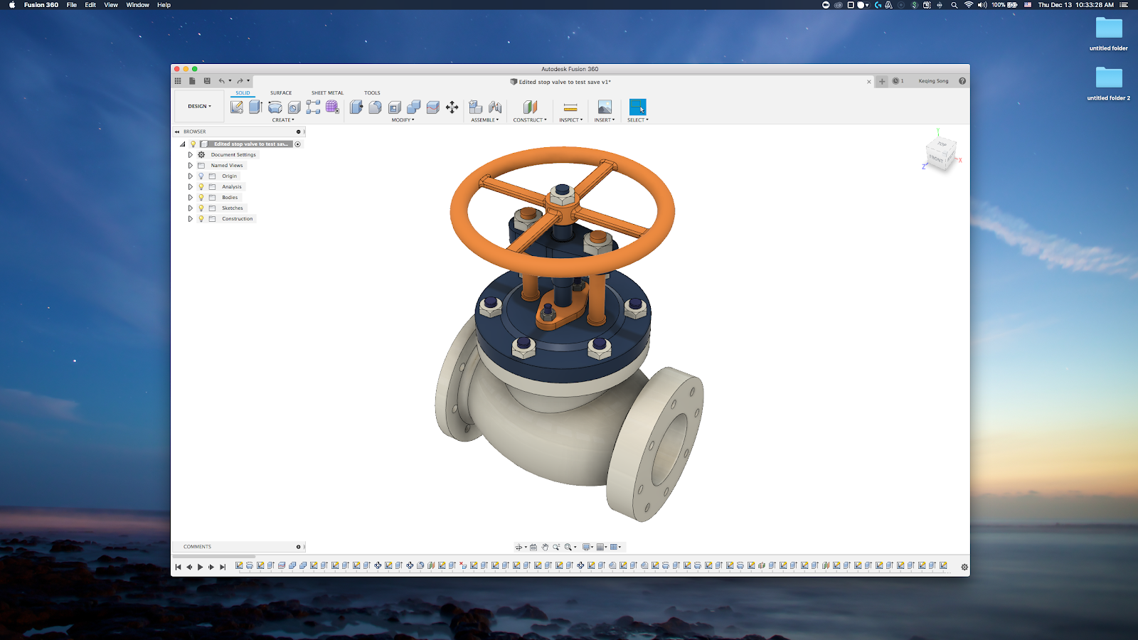
The toolbar looks even better with UI Preview turned on, eliminating that gap between the app frame and the toolbar itself. Some key benefits to the modernization effort include:
- Colors – neutral colors mean less distractions
- Icons – we tweaked the icons so they are less cluttered
- Document tab – takes full width so long design names can be displayed by default
- Tab tooltips – now will appear when you hover over any document tab
- Tab overflow – now you can pick exactly which tab to go to via a familiar drop-down menu
- Saving document – now when you save a design, the icon in the document tab will reflect “saving” or “saved”.
- Opening document – you’ll notice a progress bar at the bottom right corner and a message saying “Opening document…” so you know that Fusion 360 is working in the background.
If you haven’t seen the UI modernization blog post yet, be sure to check it out. It goes into way more detail about what has been improved and how it compares to the old experience.
Modeling
[icon name=”gift” class=”” unprefixed_class=””] New! Tapered threads for holes
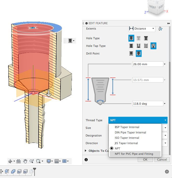
Now when you want to make a hole on your design by using the Hole command, you’ll notice that we’ve added a new Hole Tap Type called “Taper Tapped”. This enables you to choose between a variety of thread types, include NPT, as well as NPT for PVC piping and fitting. Right now the threads are only cosmetic, and making them modeled like how our existing Thread tool does is definitely part of our plan moving forward.
[icon name=”gift” class=”” unprefixed_class=””] New! Bend Command for sheet metal parts made from Sketch
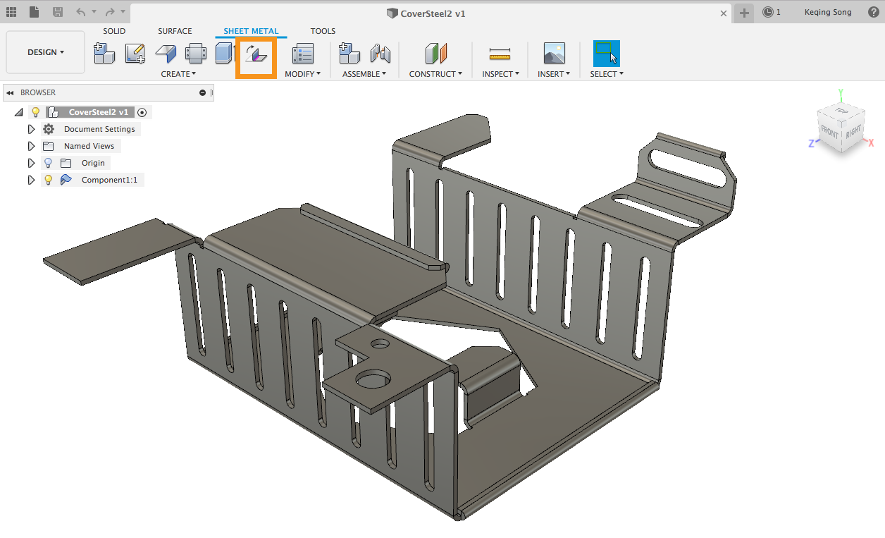
If you have sketches or DXF files you’d like to use to create sheet metal parts out of, you can now do it with a new tool called Bend. This tool enables you to select sketch geometry and use them as bend lines for your sheet metal flanges.
[icon name=”lightbulb-o” class=”” unprefixed_class=””] Pro-tip: To do this right, you’ll have to use the Flange tool and create an sheet metal flange from your whole sketch. While you’re in the Flange command, make sure that you select “Side 2” as the direction of your flange.
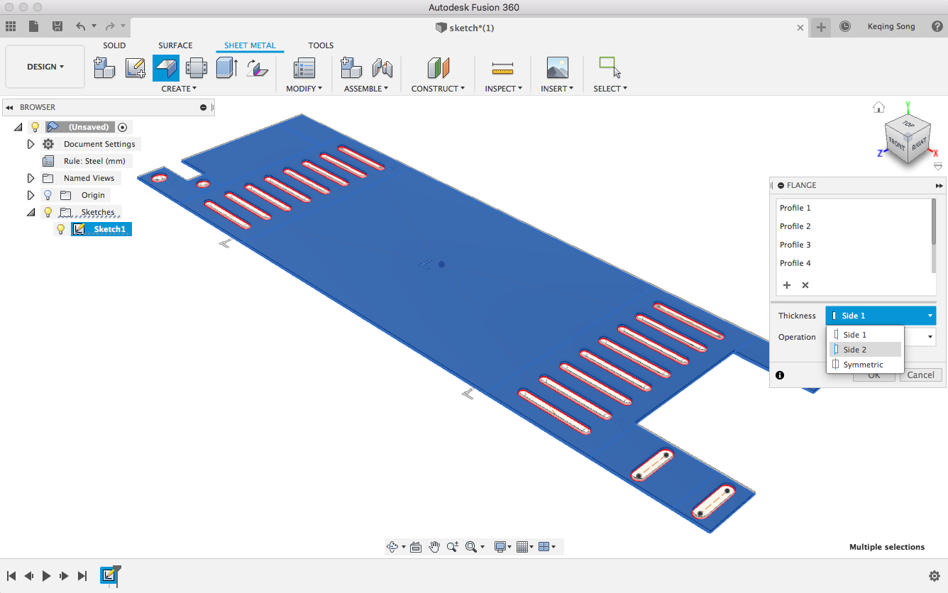
Once you’ve got your flange created, make sure your sketch is still visible and select the Bend tool to begin creating your bends.
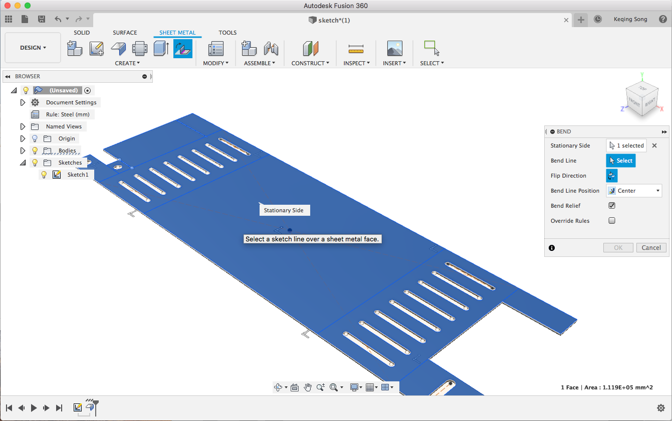
[icon name=”lightbulb-o” class=”” unprefixed_class=””] Another pro-tip: Selecting the stationary area matters. It may seem like the entire face is selectable, but where you click will determine which section of the flange will remain stationary, so select it with the right intentions.
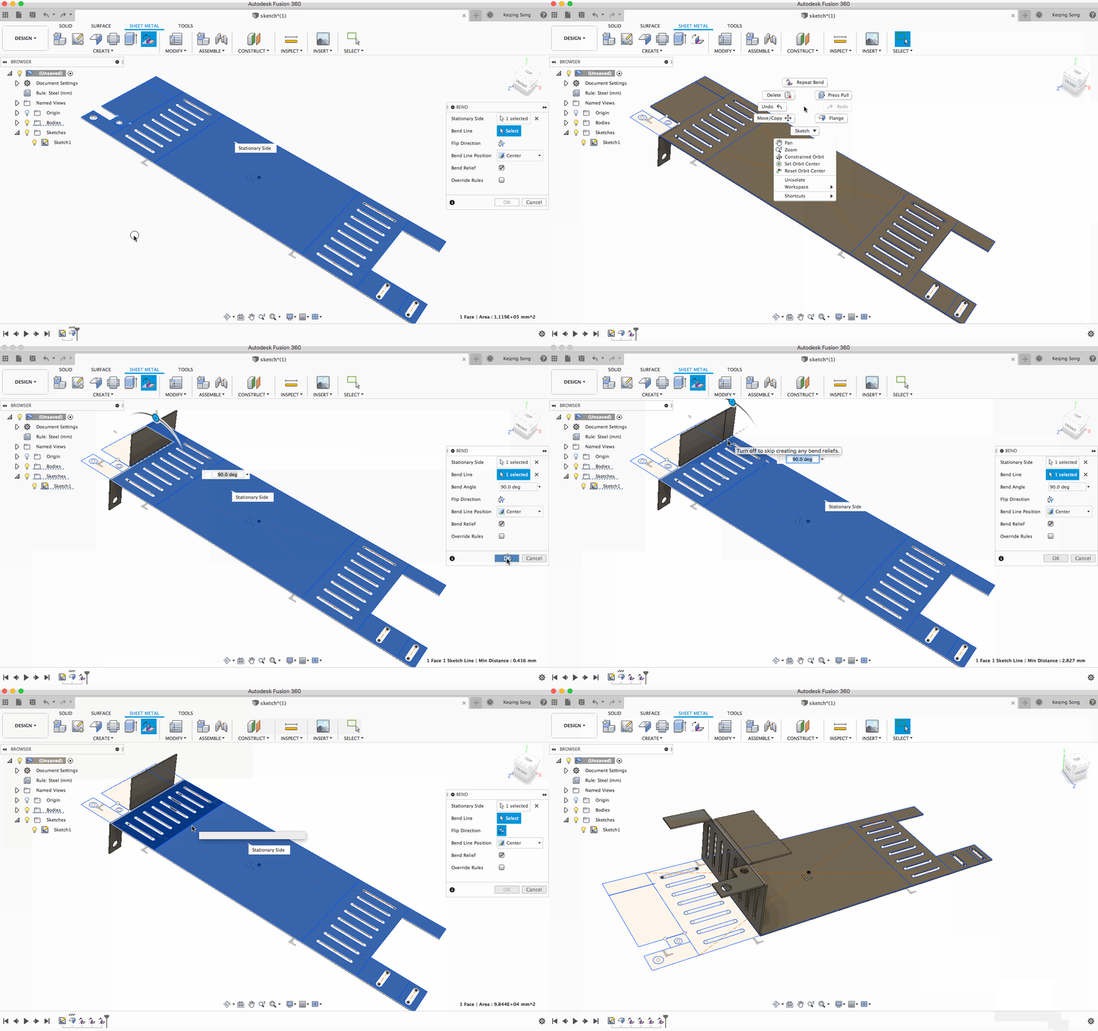
[icon name=”lightbulb-o” class=”” unprefixed_class=””] The last pro-tip has to do with the order of the bends you want to create. Typically if you think about how you would fold a piece of paper, you would start with the largest bends first and then work your way to the smallest bends last. With the Bend tool, you’ll want to start with the smallest bends first, and work your way into the largest bends. This is due to how the the fact that the sketch you’re working with is stationary, and does not project onto the flange.
[icon name=”thumbs-up” class=”” unprefixed_class=””] Improved! Select face or feature in the Fillet Command
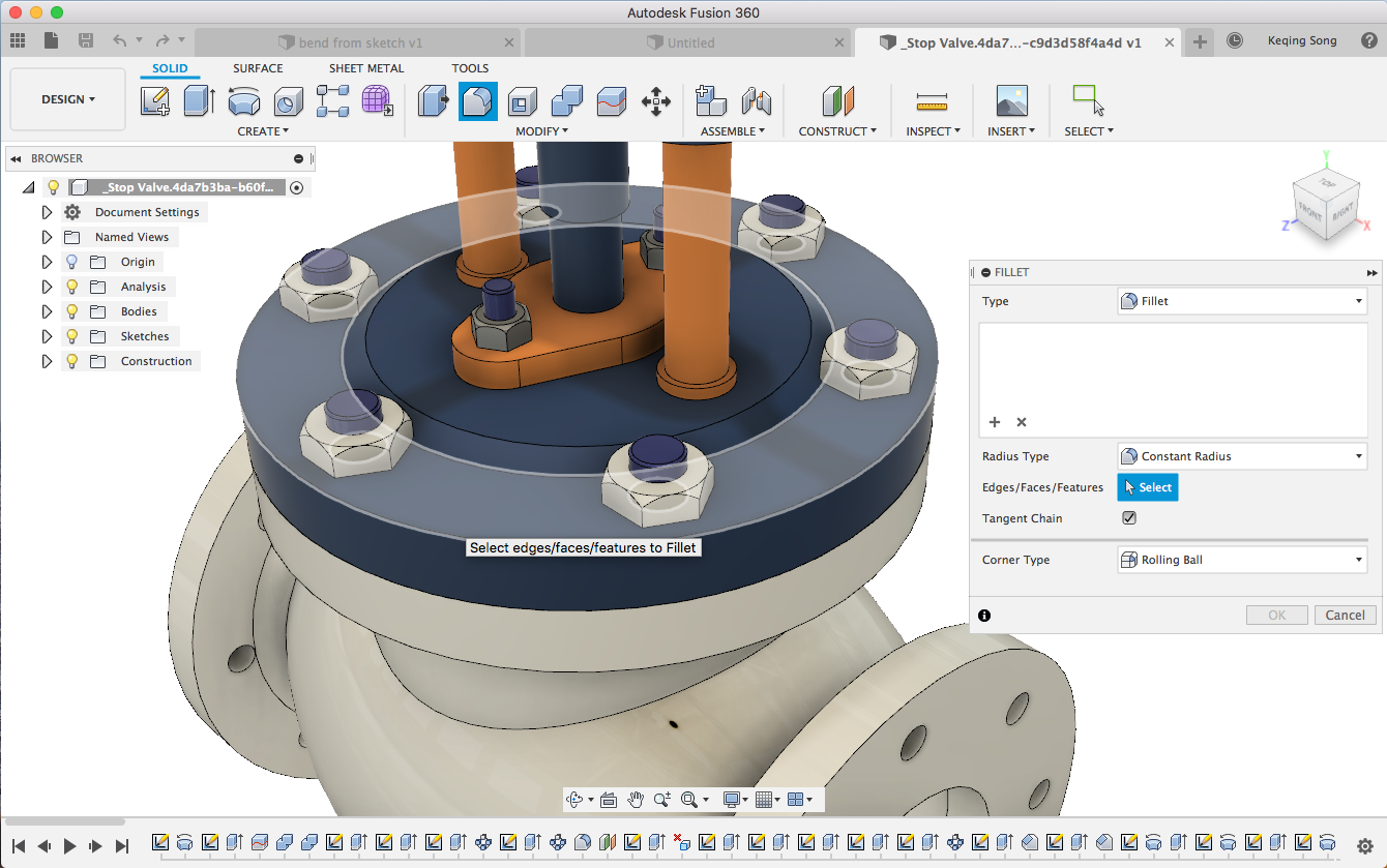
So yeah, based on popular demand and usage data, we are reintroducing this behavior so that it’s easier for you to select what you want to Fillet, without the initial buggy drawbacks. Now when you hover over your design, you’ll be able to select faces or edges to Fillet. Pro-tip: to get the faces to highlight, try zooming into the model so you have more surface area to grab. Holding down the selection action will also give you the option to select-through.
[icon name=”thumbs-up” class=”” unprefixed_class=””] Improved! Use model edges as Mirror Line
Previously when you wanted to mirror sketch geometry, you could only use another Sketch line as the Mirror Line. Now, instead of creating arbitrary lines just for the mirror reference, you can use model edges as Mirror Line.
[icon name=”thumbs-up” class=”” unprefixed_class=””] Improved! Move dimensions after they’ve been placed
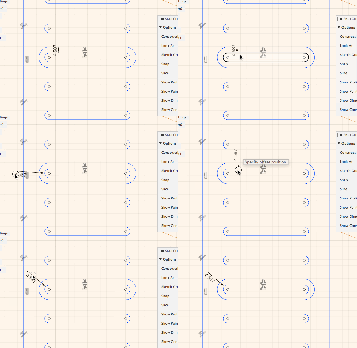
If you dimensioned a Sketch Offset, there were times where the dimension was automagically placed in-between the actual offset space, which made it appear awkward. Now when you dimensioned an Offset, you can move the dimension to somewhere more clear.
[icon name=”thumbs-up” class=”” unprefixed_class=””] Improved! Show and hide dimensions
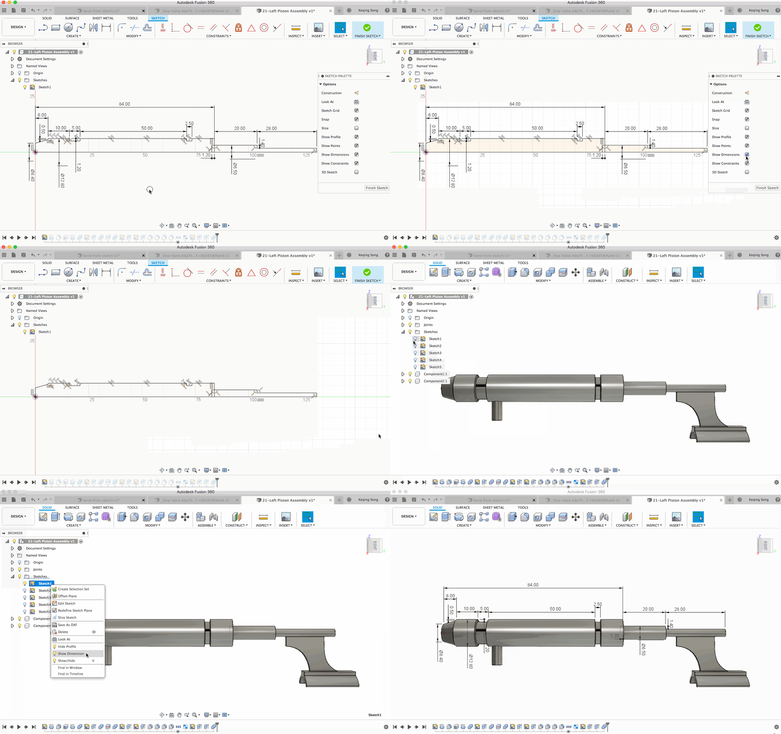
Based on your feedback, we’ve also added the option to show/hide all sketch dimensions, so that your sketches can be cleaner than a bar of Dove soap. Access it from the Sketch Palette when you’re in Sketch mode, or right-click on the Sketch entity in the browser and select Show Dimension to make them visible (assuming that your Sketch is also visible).
Generative Design
[icon name=”gift” class=”” unprefixed_class=””] New! New toolbar icons for Explore

We are continuing to refine the Explore experience in Generative Design. Now when you’re looking at a single outcome, the commands that were previously spread across different areas of the toolbar have been gathered into a more practical layout and are sporting a fresh visual treatment.
[icon name=”thumbs-up” class=”” unprefixed_class=””] Improved! Ability to download usable outcomes
You told us that some of the downloaded outcomes that you’ve brought into Fusion 360 opened with sick features (red features in the timeline). To remedy this issue, we have implemented an additional conversion approach that does not include design history that will help ensure you always get a valid CAD outcome.
[icon name=”thumbs-up” class=”” unprefixed_class=””] Improved! Milling dialog intelligence
We uncovered an issue where the milling parameters (Minimum tool diameter, Tool shoulder length and Head diameter) were not paying attention to one another, which wrongfully allowed you to define an invalid combination of values. Now the dialog is much smarter about what’s valid and what’s invalid.
2D Drawings
[icon name=”gift” class=”” unprefixed_class=””] New! Tapered Threads support
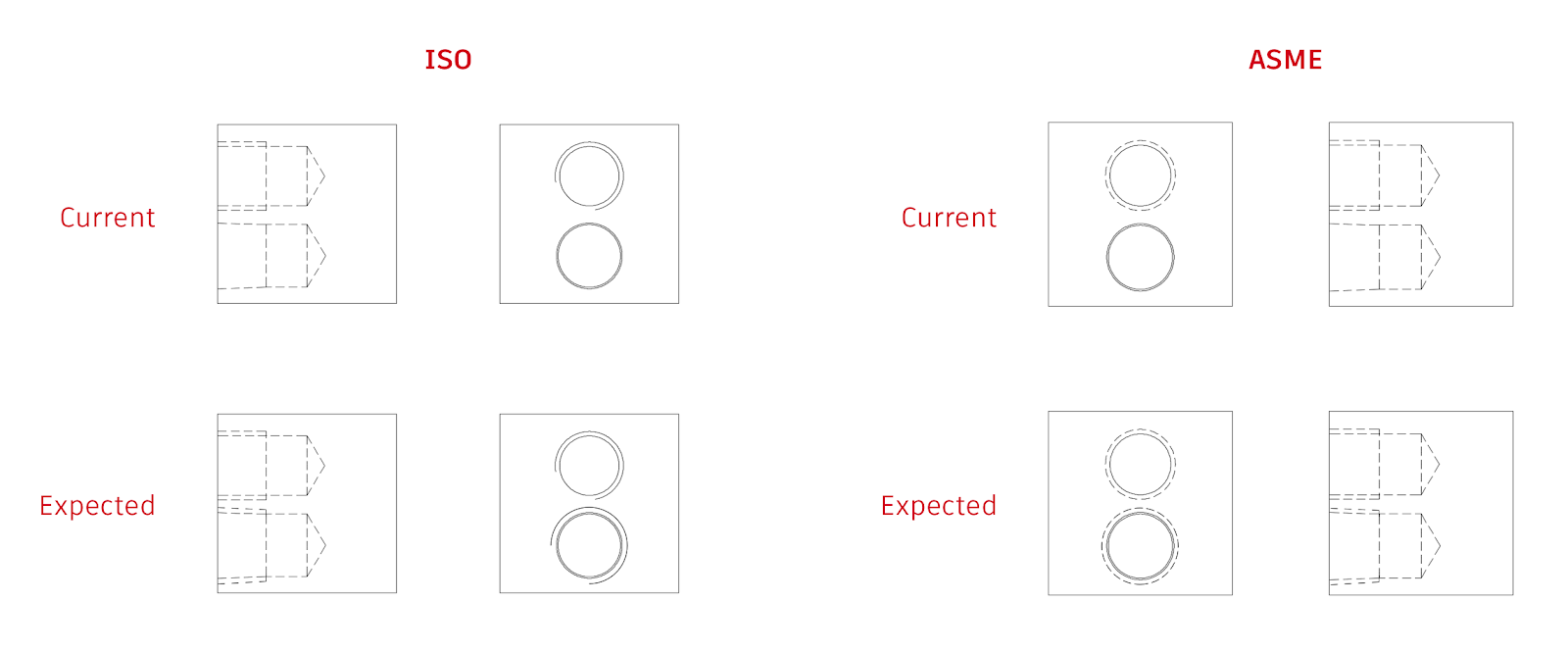
With tapered threads being available in the Hole command, you’ll need to show it on a 2D drawing as well. Depending on what standard you use (ISO or ASME), you’ll now be able a to properly differentiate tapered threads in side and front views on a 2D drawing.
Manufacture
[icon name=”gift” class=”” unprefixed_class=””] New! Stock Simulation Comparison
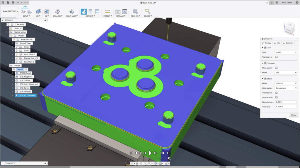
There is a new option in the simulation stock “colorization” dropdown to use “comparison” colorization. Colorization of the stock often gives you a quick and good overview of potential machining issues relevant for both part quality and cutting performance. This will color the simulated stock with three colors, blue for excess stock, green for stock that is within tolerance, and red for gouges. What is considered “within tolerance” is determined by two numeric text boxes, “Stock to Leave” and “Tolerance”.
[icon name=”thumbs-up” class=”” unprefixed_class=””] Improved! More control over angle of cutting pass in thread milling
Zachwenner suggested to us that he needed better control over the start position in thread milling. Some threads need to be “timed” at the correct start angle in order to interface properly with some parts. Based on his IdeaStation submission and the support it has gathered, The 2D Thread Mill toolpath now has the ability to adjust the angle at which the cutting pass for the thread tool-path contacts , potentially with respect to a particular feature (e.g. a point)
[icon name=”thumbs-up” class=”” unprefixed_class=””] Improved! Slot tool in Swarf & multi axis contour
paysagine wanted to use the slot tool definition for multi-axis contour and swarf toolpaths. Seth Madore was able to help him with a workaround, but we thought it would be best to actually make this work properly, so we got this sorted out and made it into reality.
[icon name=”thumbs-up” class=”” unprefixed_class=””] Improved! Use even step-downs for 2D Face tool-paths
When using 2D Contour and 2D Pocket with multiple depths, there is a an option to “use even step-downs” which reduces the maximum step-down amount so that each step can be equal. Now this option is also available for the 2D Face tool-path.
[icon name=”thumbs-up” class=”” unprefixed_class=””] Improved! Use ‘select same diameter’ in Bore, Thread & Circular Holes
ArjanDijk asked to have a “select same diameter” option for boring, circular milling and threading on holes as it works for drilling holes. We agree that doing this one by one can be a very tedious task, so we made it so and now when you have the option enabled, Fusion 360 will find all the same diameter holes and will select them in addition the one you’ve selected.
[icon name=”thumbs-up” class=”” unprefixed_class=””] Improved! Select same diameter for milling boss
Having a Select same diameter for bore, thread and circular holes is nice, but selecting same diameter for outer holes (bosses) is equally nice. Now you have both.
[icon name=”thumbs-up” class=”” unprefixed_class=””] Improved! Setups with multiple bodies
If you have setups with many bodies, sometimes it can be frustrating when they’re all automatically selected. Now, you can be selective about your selections, depending on how many bodies you have in your setup. If your setup has one body, that body gets selected automatically. If your setup has 2 or more bodies, nothing gets selected.
[icon name=”thumbs-up” class=”” unprefixed_class=””] Improved! Rest from file option is back
Nick.rempp asked about why rest machining from file option was no longer available. Apparently we removed it in the last update because it was a broken and we thought alternative workflows were better. Turns out we we wrong – it wasn’t as broken as we thought, and some of you were still being very productive with it. Now this option is back.
Notable fixes [icon name=”wrench” class=”” unprefixed_class=””]
Usability: Stop Sketch. Exit Flat. Finish Form. There were so many variation of leaving a mode, so we cleaned it up. Now all the Finish commands say “Finish” instead of “Stop” or “Exit”, making the action consistent throughout the different environments.

Usability: Tcrxelizondo and others have reported to us that sometimes their file uploads seemed to have been stuck and never reaches 100%. We went back to our upload pipeline and flushed the pipes. Now uploads should flow smoothly without a hitch. If you come across some blockage again, be sure to tell us in the support forum and we’ll help you get sorted.
Sketch: Apparently Fusion 360 didn’t allow you to use an axis to be the Mirror Line in Sketch > Mirror. Our bad -now you can.
Generative design: There was an issue where obstacles were being ignored if any of the bodies that were defined as an obstacle were removed in the Edit Model workflow. We have fixed this issue and all obstacles are working as expected.
2D Drawing: MariusBaard reported in our forums that his drawings parts list was showing the wrong number of parts in his design. Something was tripping the logic built into the smart templates, so we went into there and gave a clean scrub. Now parts lists should accurately reflect what is in the design.
Manufacture: We fixed an issue in turning profile roughing and profile finishing operations where the tool was cutting deeper than it should. That’s never fun to see.
Manufacture: There was another issue where lead-in and lead-out angles at the back of the part were not being honored for turning profile roughing and profile finishing toolpaths. We had spent some time disciplining Fusion 360 and now it knows not to step out of line.
Manufacture: jharman2 reported that the nose radius option in Turning disappeared for some weird reason. Now corner radius input field is no longer hidden on the Insert tab when editing a tool after clicking on the ‘Edit Tool’ context menu option on a particular operation. Also, tools modified in this manner no longer have their corner radius value reset to 0 which had the potential of causing gouges.
Manufacture: 2D contour toolpath will now regenerate after changing Tabs settings.
Manufacture: Previously in 2D bore, you had to make two separate bore operations since they can’t bore two open bores together. They should be able to do it in one.
UI preview: Bestillsicsu made us realize that we forgot to add the Sheetmetal Rules command in the Modify drop-down menu, even though the command is already visible in the toolbar by default. As a good rule of thumb, commands that are visible on the toolbar should also be in the panel drop-down menu.
–
That’s it for this update, stay tuned for the next one as well continue to make Fusion 360 better than ever. Yours truly,
Keqing and the Fusion 360 Team
[icon name=”bullhorn” class=”” unprefixed_class=””] Notice something isn’t working properly? Tell us about it in the support forum and we’ll help you get sorted.