
We encountered an odd behavior where if you were editing a locked sketch dimension, started moving your cursor, and changed the value of that locked dimension again without pressing the ENTER or Tab key, the dimension wouldn’t update the sketch. Now it does.
We fixed an issue that was causing some of you with macOS machines to hang on startup of Fusion 360 (or a noticeable decrease in startup speed).
___
V. 2.0.9930
We noticed that if you where in the Additive tab and clicked on the Move command with the Setup dialog still active, Fusion 360 got really confused didn’t want to go any further. This also happened when you were in the Move dialog and clicked Cancel, knowing that you haven’t selected a machine in the Setup dialog yet. We untangled some wires and now both issues are gone.
blakebarrier reported that when he was trying to generate a toolpath, he kept getting a pop-up message that “The software component within Fusion360 that calculates operations has closed unexpectedly. Fusion360 remains open, but some operations have not been generated.” We got working on this issue and found that it was related to an Adaptive Clearing with rest machining issue that we’ve fixed. Now this is fixed too.
Apparently a recent bug emerged where if you have “sync visibility with active setup” active, then created a new setup, the visibility did not sync up correctly. It was only when you re-activated the setup that the visibility took effect. Now it should sync correctly.
We fixed in issue where if you accidentally crash during a palette command, it was possible to somehow link the Palette to Fusion 360’s Native UI.
We also fixed an issue regarding _dependentParameter_s method. When a user parameter depended upon a model parameter using the _dependentParameter_s method on that model parameter, an access violation exception occurred, which caused Fusion 360 to crash. Now this method should work properly again.
We cleaned up some dialog formatting issues in the add-in install dialog for certain add-ins that contained lots of information and text. Now it should more consistent across macOS and Windows.
We fixed a few nasty bugs while testing Nesting workflows. If you started to create a Nest Study andpressed CTRL/COMMAND, the browser node disappeared for no reason. If you clicked OK, the nest study would fail. Trying to create a new Nest Study caused Fusion 360 to crash. This has now been sorted.
If you were in the Setup command and decided to create a new Nest Study with the command still active, Fusion 360 refused to cooperate and crashed. Now it will no longer crash, and you’ll be presented the Nest Study dialog as expected.
When using Edit Arrange on a previously modified Component Orientation angle value in the Nest & Fabrication Extension, we noticed that the Orientation field didn’t display the manually modified value that you’d expect. Now it does.
___
V.2.0.9854
StuffAndyMakes reported an issue where entering dimensions for an initial sketch that was locked did not affect the size of the sketch. Do this should update the sketch to reflect the new dimension, and now it does.
arlimbad222 and a number of others have told us that .STL machining was not working properly. Fusion 360 generated the toolpath, but completely ignored the .STL file, placing the toolpath at a fixed height and violating the .STL surfaces. This is now fixed as well.
Some of you experienced instability with the 3D Adaptive Clearing toolpath where rest machining was causing Fusion 360 to crash. Sorry about that – this is now fixed.
We found some wonky behavior around how NC programs were being output if you had selected a different file path as output location. The new output folder typed in the Compare and Edit dialog was reset to default inside NC Program dialog. Now Fusion 360 will remember the output folder associated with the NC program.
___
V.2.0.9849
Usability
New! Know who’s working on what with Design Reservation

Previously if you and your team were working on a single Fusion 360 project, you had to be careful about who is making changes to which document. Changes saved to a document are versioned, however it wasn’t easy to know who is working on what (without staying on top of everyone’s activities), nor was there a way to explicitly reserve a document. Now, Design Reservation makes this all possible by building on top of functionality that currently exists, as well as expanding on what is possible.

Now if you and your team are working on an assembly with external components (xrefs), you’ll notice avatars and reservation badges placed on the documents that you and your team members are currently working on. Badges will appear in the document tab, browser entities, and the data panel.
Design Reservations is a part of our Assembly Concurrency workflow. Coupled with the ability to edit externally referenced assemblies with Edit-in-Place and working with Local and Assembly Contexts, this enables you and your team to work closer together with more transparency. There’s a lot more to cover, so if this functionality is relevant to you, be sure to check out our detailed blog post.
Learn more about assemblies and Design Reservation
New! Use Arrow keys to navigate the design browser
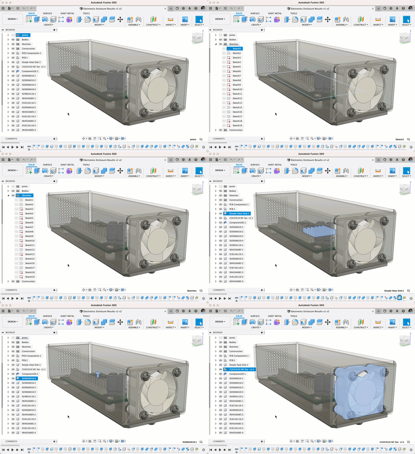
Arrow keys – cast aside by gamers but still beloved by everyone else. If you’re wondering what you could be using your arrow keys for in Fusion 360, you’re in for a treat. As part of this update, you are now able to use your arrow keys to navigate through the design browser, digging into folders, components, and component assemblies. Now you can use your mouse for something else as you navigate with your trusty arrow keys.
[expand title=”See notable fixes”]
- Measure DXF files in the 3D web viewer
This was previously not working. If you uploaded a DXF file, went to Fusion Team and got to the 3D web viewer of the design, activating the Measure tool didn’t actually let you select any edges to measure from. This is now fixed. - We got a few reports telling us that Fusion 360 throwing an error when you tried to upload SolidWorks 2021 SP1 files. Now it works without issues.
- schack.lindemann reported that some plastic appearance materials like translucent plastics, foam, wax, and gemstone did not respect the opacity percentage change previously made to the body. Now it does.
- Awhile ago, eric.beeckmans told us about an issue he was experiencing around working with SVGs, and how he was getting a “Failed to solve” warning he was able to workaround. Turns out this error was caused by a sketch solve issue. This issue has been resolved and you should no longer be getting this error unexpectedly.
- gyorgypalfal noticed that the handy measurement info that is usually displayed in the bottom right corner of the Fusion 360 canvas (when you have geometry selected or when you are trying to measure geometry) was not showing up for him. In this thread, we discovered that this issue was affect macOS 10.13 machines. We fixed this issue, but also would like to remind you that Fusion 360 support for 10.13 will end in April of 2021, so plan accordingly.
[/expand]
Sketching & Modeling
New! Sketch Chamfer
Sketch Environment > Modify > Chamfer

Yup, that’s correct. Now under the Sketch > Modify drop-down menu, you’ll find not 1, but 3 Sketch Chamfer tools at your disposal: Equal Distance, Distance and Angle, and Two Distance Chamfer.

Once you’ve selected the one you want to use, the Chamfer tool Feature Options will appear in the Sketch Palette. This will make it easier for you to switch to a different Chamfer type, without needing to go to the toolbar.
Learn more about chamfers in sketches
Improved! Joint Origin disc updated
Design Workspace > Assemble > Joint Origin as well as other tools that require Joint placement
One of the things that sets Fusion 360 apart from everyone else is our use of Joints when creating assemblies. Joints dictate the kinematic relationship between 2 components in 3D spaced, and the Joint origin disc was not clear at conveying a three-dimensional coordinate system.

We improved the joint origin glyph so that it clearly shows the three axis of 3D space (X, Y, and Z). Now when you apply a Joint Origin on a component, you can easily tell which direction that Joint Origin is facing.


We have provided the Object Visibility option for Joint Origin Axes. We’ve also provided the Object Visibility option for Joint Origin Axes in the Object Visibility section of the Nav bar, as well as updated all related Joint Origin icons in the toolbar, timeline, browser, dialogs, and context menus.
Learn more about joint origins
Improved! Capture position for Joint and As Built Joint
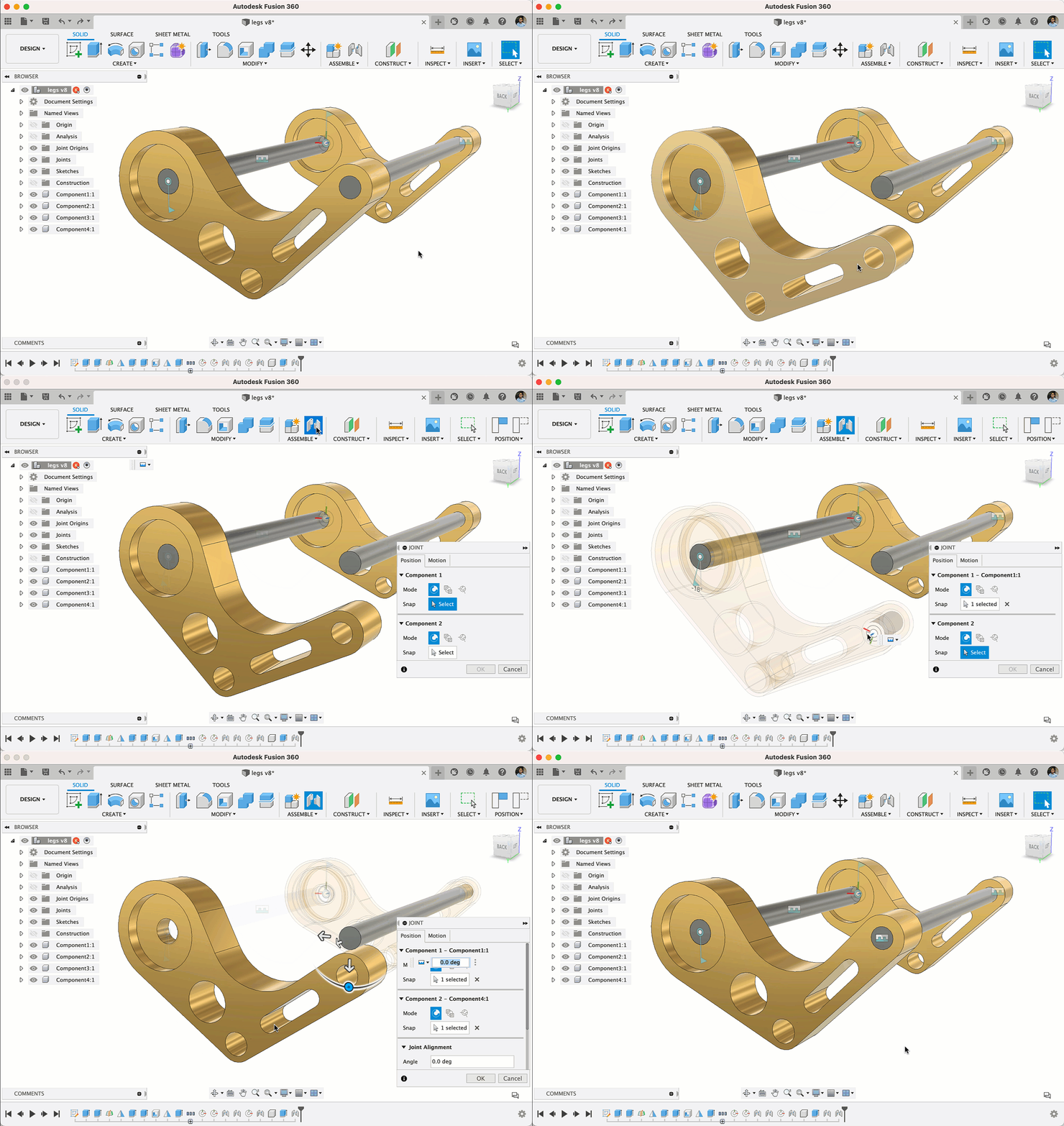
If you’ve created assemblies in Fusion 360, then you’ve probably come across the Capture Position dialog. This dialog appeared when you tried to create a Joint after moving a component. In many cases, you were just moving a component so that it was out of the way, making it easier for you to apply the joint needed. This Capture Position dialog was confusing to many of you, and was often unnecessary.
Now the dialog will no longer appear when you’re creating a Joint or As-built Joint. Also, the capture position feature is created in timeline only if it is necessary, otherwise Joint is created in pending capture state itself. This avoids unnecessary capture position features in timeline. For the cases where the capture position is necessary before creating the joint (like the case where the custom axis for joint motion is selected from a moved component), the capture position feature is silently put in the timeline (i.e. without the prompt) followed by the Joint feature.
Learn more about capturing component position
Improved! Fillet and Chamfer Chaining
Design > Solid Tab > Modify > Fillet or Chamfer
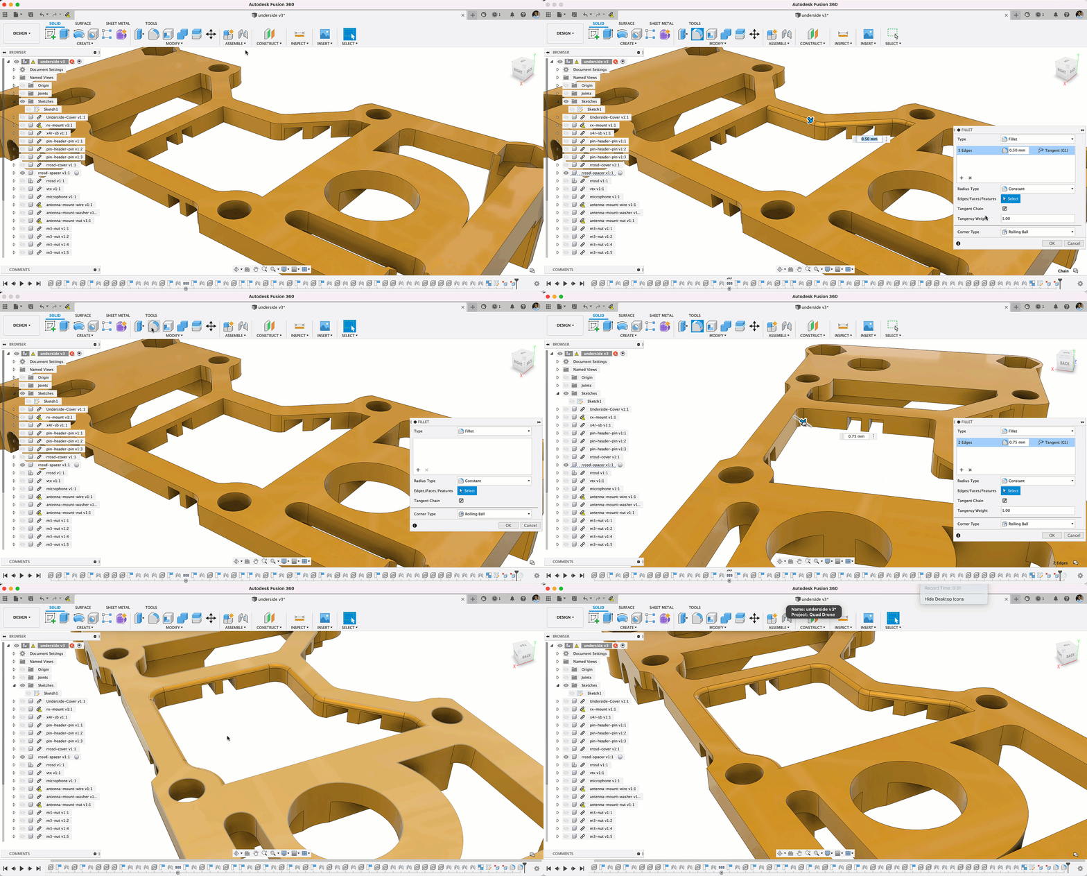
The Fillet tool has seen some significant improvements last year, and now we’re back with another good one. Previously when you applied a fillet on an edge, the command will chain edges where there is curvature created. If you went back a couple of steps before that fillet was created and added more fillets to the perpendicular edges, the chained edges will not update. Now when you go back and add new fillets to the perpendicular edges, the chained edge fillet will detect the new curves and chain them automatically.
Learn more about tangent chaining for fillets and chamfers
Improved! Custom parameters are now automatically added to Favorites
Many of you have asked for this, and we’re glad that we can finally tell you about it. Now when you create named dimension, that named dimension parameter will be automatically added to the Favorites section of the Parameters dialog. With this improvement, you no longer have go hunt down the right on and add it manually.
Our friends at Bommer are particularly excited about this. If you’re using Bommer for Fusion 360, you can use your named parameters to perform calculations inside your bill of materials. Check out their blog post to learn more.
See Bommer’s blog post
Learn more about parameters
Improved! Sketch Text on Path now puts text on the correct side of the curve
Previously when you placed text on a path in Sketch > Text on Path, the text sometimes appeared flipped or on the wrong side. We tweaked the code so that the text will now appear on the correct side of the curve by default, closer to what you’d expect.
Improved! Export New Text as DXF created from Sketch
We noticed a bug where if you tried to save a sketch that includes text as a DXF, the text was weirdly omitted from the exported DXF file. Sorry about that; now sketch text is included as part of your exported DXF file.
Improved! Centerline option for projected lines
We introduced the ability to turn sketch lines into cetnerlines from the sketch palette in the last update. Now if you project a line from one plane/surface onto another plane/surface, the projected line can also be turned into a centerline directly from the Sketch Palette > Options > Linetype.
[expand title=”See notable fixes”]
- mah6786 told us about an issue where he was unable to delete a group of actions in his timeline. Turns out there was something funky with how Fusion 360 handled German words, which made it impossible to delete the group. This issue is now fixed.
- theofficialjoshuataylor reported on the forum about how he was noticing a lot of instability with Fusion 360 when he tried to save modifications he made to .step and .iges files he had imported into Fusion 360. He later discovered that if he turned on “Capture Design History”, he was able to save his changes without issues. After reading his CERs, we discovered that it was related to an add-in he was running. We sorted this out and now it should save fine without the workaround mentioned.
- worknstuff ran into an issue where editing an Extrude feature that was performed on an inserted sketch caused Fusion 360 to crash. We followed the clues and found the root cause of the issue in the code, and now it’s should be working fine.
- benjamin.leedyMVWKP was confused about why he’s been seeing this error message telling him that the rail he selected was not smooth, even though he carefully made sure that the rail was intersecting with the profiles as a simple Fit Point Spline. We dug deep into the code and found that the error was actually related to a separate issue, and not the rail that was selected. This is now fixed.
- There were instances where a bug in the Fillet tool was causing some designs to crash Fusion 360 when you tried to Save Copy As from the browser. We cleaned up the code and now it should save just fine.
- We fixed issue where when you tried mirror a sheet metal body with the Mirror tool, the actual result was different from what the preview result showed (which was the correct one). Now the actual result matches the preview.
- alanmeaney noticed that when running Fusion 360 on macOS Big Sur 11.1, additional options in the Sketch Text dialog failed to appear for some odd reason. After digging into this, we found out that the issue was related to the use of multiple monitors at different resolutions. We’re happy to report that this bug is gone and Sketch Text now works as expected.
- We fixed a Hole pattern bug where if you set the termination option to Adjust, it doesn’t actually adjust to meet a desired surface; it used the same termination shapes to the original hole. Now the command will obey the option correctly.
- Apparently the Mirror command was misbehaving itself in the direct modeling, where the resulting mirrored body was placed far away from the original. Sorry about that, this has now been fixed.
[/expand]
Electronics
New! Synchronizer Tool
File > New Electronic Design > Schematic > Validate > Synchronizer

Fusion 360 uses the Electronic Document to synchronize the schematic and PCB live. Meaning that changes done to the schematic will be instantaneously reflected on the board. There are times that this synchronization can be lost due to file corruption or by working on one of the editors while the other one was closed (seriously, don’t ever do that). Traditionally, fixing PCB and Schematic annotation meant continuously running electrical rule checks and fixing each item manually. In this update, the synchronizer will enable you to restore consistency easily and automatically. It also paves the way for some exciting workflows in the near future.
Need to match an existing schematic with a PCB used in a different project?, no problem. With the designs loaded, setup your synchronizer preferences and in moments that PCB will be synchronized with the schematic. If you have ever run the diff tool in a text editor or IDE the interface will be familiar to you. It will provide you with a dialog box listing the differences between the schematic and PCB. You will be able to selectively determine what differences from the schematic that will be transferred to the PCB.
Improved! Edit-in-Place PCB in Design Workspace

In the design workspace, it is possible to edit the PCB component position. This allows you to fine-tune part placement at a precise location, making sure that connectors are properly exposed, and components are not interfering with the enclosure. Previously after moving components around in the design workspace, you had to take a few additional synchronization steps to update the PCB. In this latest update, you now have the option to update the PCB including routing from the design workspace, without manually forcing this synchronization.

Another time saving feature added to this update, gives you the option to push the PCB changes to the 3DPCB or directly to the 3DPCB in the design workspace.
Learn more about Edit-in-Place
Improved! Package Generator User Interface
File > New Electronics Library > Package Editor

The package generator is one of the best tools in Fusion 360 because it allows you to create complex electronic components in a matter of minutes. A task that could take much longer without it. In this update, all component options are now tabbed instead of a single scrolling dialog box. This will make it much easier to access thermal options and manufacturing tolerances.
Learn more about Package Generator
[expand title=”See notable fixes”]
- franck.malepart reported on the forum that after loading some of his design files, the undo function didn’t work properly. Sorry about that; this has been taken care of.
- xpuipc and rbkyorem made us aware of an issue while hiding a polygon while working on their PCB and pushing the 2DPCB to 3DPCB caused Fusion 360 to crash. We dug into this and got it working again. Polygon will now work as expected, we thank you for taking the time to report it.
- Yaqoubdesign, on your forum post you indicated that uploading exported library would fail. After reviewing your post, our developers looked into it and found the problem. This issue has been resolved in this update.
[/expand]
Generative Design
New! Obstacle Offset Command
Generative Design workspace > Design Space > Structural Loads
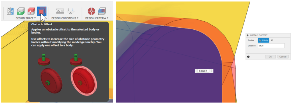
If you have been using generative design with obstacles in your design space, you have probably noticed a time or two that the generated geometry grew right up to your obstacles or even interfered with your obstacles around a tight corner, leaving an unexpected notch or cutout in your final shape because of the obstacles being cut from the generated geometry. The solution to this was to make your obstacles a little bit bigger and then remove the cut operation from the parametric recipe, which was tedious and not obvious. With this update, we have a new command, Obstacle Offset, that will allow you to virtually “inflate” your obstacles as part of the study setup without having to alter your original CAD geometry. The solver will now generate geometry based on this “inflated” obstacle definition, giving extra clearance so that your generated geometry is sure not to touch or interfere with your actual obstacles.
Learn more about Obstacle Offset
New! Remote Moment Load Type
Generative Design workspace > Design Conditions > Structural Loads

We heard from many of you about challenges accurately creating your generative design setups due to moments applied on cylindrical faces being limited to the axis of the cylinder. You described many scenarios where an off-axis moment was required to accurately reflect the operating conditions of the design. In this release, we have a new option for defining moments in generative design. With the Remote Moment option, you can now apply a moment to any preserve surface, cylindrical or planar, in any orientation you require. In the image below, you can see that we can now apply a moment that is not aligned to the axis of the cylinder.
Learn more about Remote Moment
Manufacture
New! Post processing to Fusion Team
In our drive to improve NC programs and unify the post processing experience (seen within the Post using NC programs feature flag), we have added the ability to post process directly to Fusion team! The new “Post to Fusion Team” option allows you to not only post code as a regular NC program, but automatically uploads that posted NC file to your Fusion team, creating a much tighter integration to the cloud.
With this, your NC file will have its own revision control and a link directly back to the reference document. It’s now easier than ever to stay up-to-date with the latest NC file, go back to an earlier version or even share a link with the shop floor to download the NC code
New! Probe Geometry inspection report

Consolidation of Probe Geometry into inspection reports. Measure critical features and dimensions, confirm that they are within required tolerances, and record the results in Fusion 360. Inspired by the reporting capability from PowerInspect this functionality allows you to include all types of measurement results in a single consolidated inspection report. It imports results printouts created by probing cycles (such as Renishaw Inspection Plus) and provides the additional benefits of graphical reporting and the ability to format and export inspection results. We have extended the capability since the original preview In October 2020 and updated the color conventions used to highlight whether results are in or out of tolerance.
Learn more about inspection results
New! Match color conventions for inspection & simulation and allow user to choose convention

Fusion 360 uses color to indicate when areas of a model exceed upper and lower tolerance values, so you can easily see any areas of the model with too much, or too little, material. Historically, Fusion 360 has used the same colors to mean different things in stock simulation and inspection. The color conventions for inspection & simulation now match, and you can choose between the two historic conventions with a setting in preferences. A legend explaining the color convention is now included both with the inspection results and in the CAM stock simulation comparison. In addition, there are changes to the color conventions used for Probe WCS and Manual Inspection- out-of-tolerance inspection results are displayed in orange, and the nominal values for Manual Inspection in black.
Learn more about selecting a tolerance color convention
New! Selection and Deletion options of toolpath segments (available in extension)
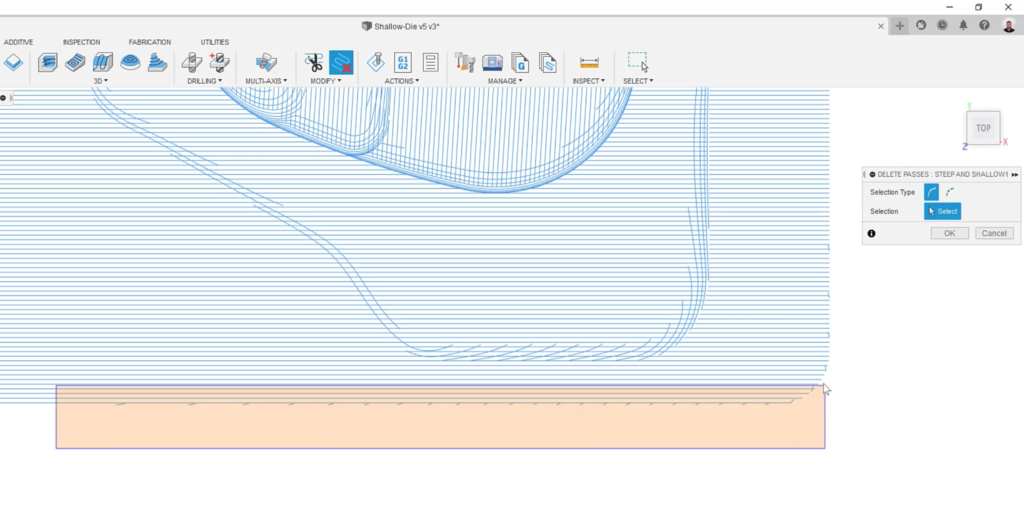
If you’re new to Fusion 360, you may not be aware that window selecting from left to right is going to give you a different result as opposed to right to left. If you window-select from left to right, only the entities that are completely included within the selection window will be selected. If you window-select from. Right to left, everything the selection window will be included, regardless of whether it is completely within the window or not. This is how window selection behaves today with model geometry and sketches, but did not pertain to toolpaths, until now.
Now you can window select left to right to catch pesky fringe toolpaths while avoiding valid toolpaths that are overlapping them without any issues.
Learn more about deleting toolpath passes and segments
New! Nesting & Fabrication Extension
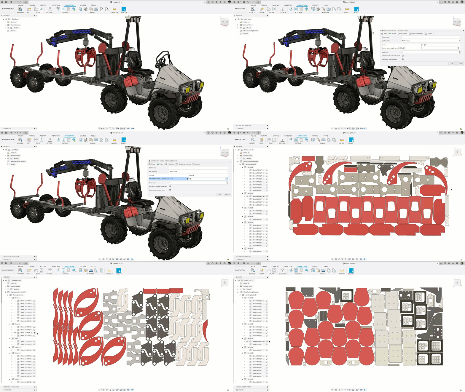
Nesting has been available as a Preview since December. We are now releasing it as part of the Nesting & Fabrication Extension. To purchase it, visit Extension Manager dialog then click Access Options. The Nesting & Fabrication Extension is also available for a 7-day trial (resets annually).
You can also reach out to a Fusion 360 representative to learn more about how to get access to this new functionality. Contact us here.
[expand title=”See more”]
You may use this extension to unlock advanced nesting and fabrication capabilities to create optimized and associative multi-sheet layouts for your sheet metal and non-sheet metal parts in preparation for cutting on your CNC machines.
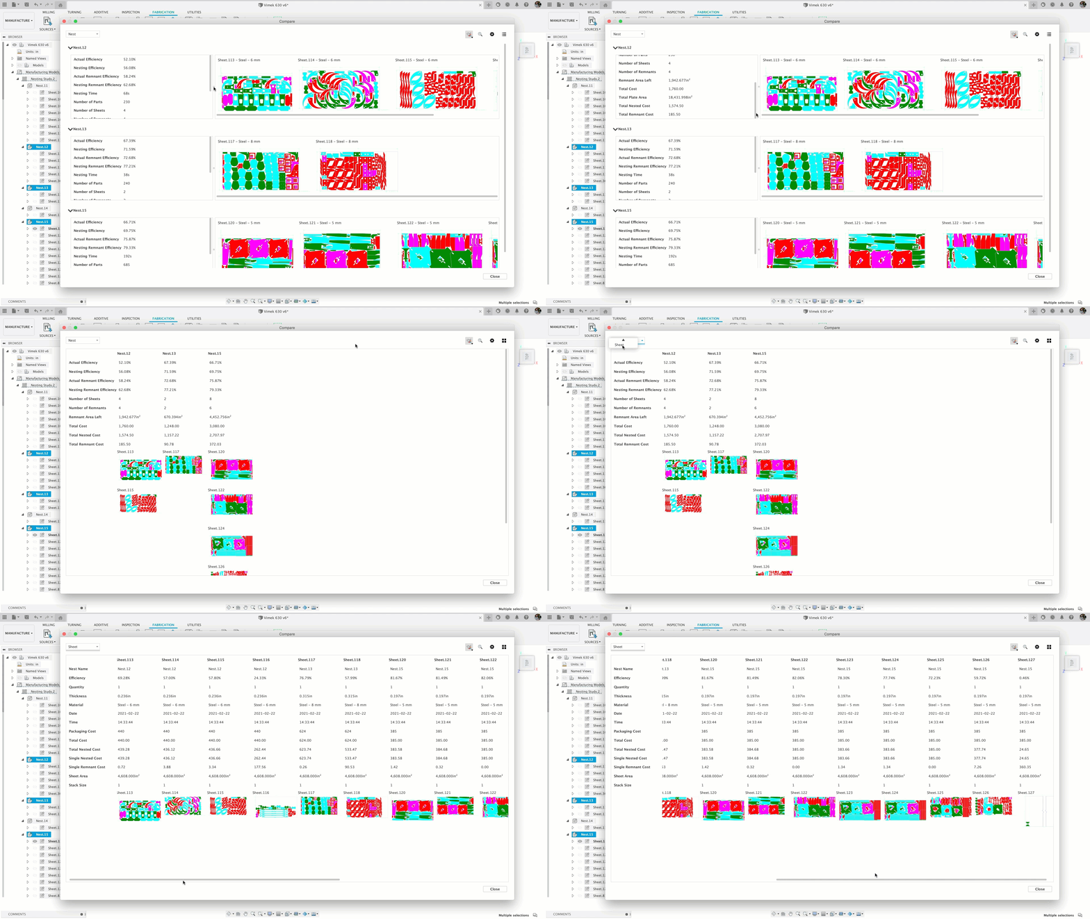
It allows you to create nest studies for parts from one or more documents to optimize material yield and minimize waste from flat raw material cutting operations. It also includes automatic material, thickness, and part quantity detection along with the ability to control part orientation and available stock sizes.
Once you are satisfied with the nest results, you can generate setups, toolpaths, and NC code from Fusion 360 or simply export nest layouts as DXF files. Customizable nest reports can be saved and shared in PDF format.
To help you get started, we created an 8-part tutorial series on YouTube, so be sure to check it out if this is relevant to you!
New and updated Nesting & Fabrication extension help topics:
- Updated: Design-level ability to exclude object types from nests
- Updated: Granular-level ability to set individual object types or exclude them from nests
- Updated: Reference topic on excluding and setting object types
- New: Work with material and packaging presets
- New: Work with nest reports
- Updated: Nest Study reference (Output tab)
[/expand]
New! Advanced Arrange in Nesting & Fabrication Extension
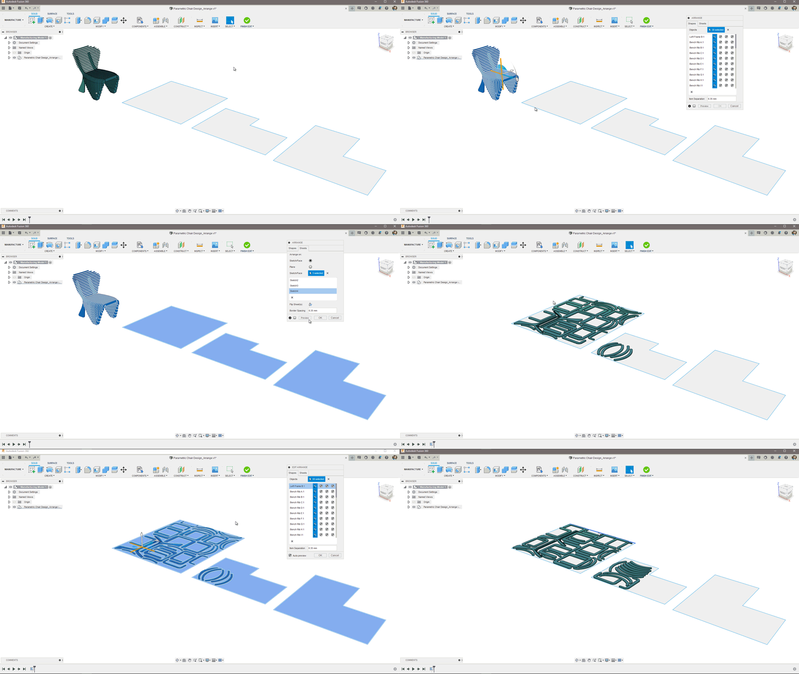
We have added Advanced Arrange as an extension preview functionality that unlocks additional capabilities for your Arrange tool. Once enabled from Preferences > Preview Features, your existing Arrange tool will allow multi-sheet arrangement and enable part rotation control. This means you can select multiple closed sketches as arrangement boundaries or simply select a plane and provide length & width dimensions and the arrange tool will calculate the number of sheets needed to arrange all selected components. Moreover, the rotation control lets you specify the initial part orientation plus allowed part rotations in 90-degree increments. For example, if you need to arrange parts at 45 degrees to conform to material grain – set the orientation to 45-deg and disable 90, 270 rotations. This will arrange the part at 45 or (45 + 180) degrees counterclockwise.
This extension preview is currently available to all users that have access to the Arrange tool (Student, Start-up, and paid subscriptions).
Check out this video made by Portland CNC:
Learn more about Advanced Arrange.
[expand title=”See notable fixes”]
- We fixed an issue reported by some of you trying to export a setup sheet using “setup-sheet=Excel-2007″.
- ed as well as others have reached out to us and told us about how their Bore, Drill, and Circular toolpaths were not behaving correctly, or were failing to generate. This is now fixed.
- Scott Moyse told us about an issue where in a Hole Recognition workflow, the holeTopDiameter value was not being updated (and became a stale value) by hole recognition itself or by manually doing a generate on the operation. We tweaked the code and now holeTopDiameter value is being updated correctly.
- Fusion 360 was becoming unstable when you tried to create a NC program for pattern containing a manual NC program. Now it won’t crashing anymore.
- When using Diameter Range for Drill selections, you can now apply “Check for Occlusions” option. This means you can now use diameter range AND avoid the unreachable holes on the opposite side of the part attached and similar.
- Previously within the NC Program folder in the browser, you weren’t able to drag and drop a NC program within the folder, even though the preview marker indicated where the new spot would be. Now you can drag and drop NC Programs objects to reorder them within their own “NC Programs” Collection.
- If you created a Manufacturing Model, selected 3D > Flow toolpath as well as a valid face, you weren’t able to then select the red bidirectional arrow to change U/V direction. Now you can.
- It seems like some of you have been experiencing an issue with Rest Machining where the Rest Machining option in all Adaptive and Pocket strategies were weirdly ignored. After updating our CAM kernel, this issue is now fixed.
- We fixed an issue where Fusion 360 was crashing when you changed a parameter of a model with Change Parameters in the Design Workspace and then switched to the Manufacture workspace.
[/expand]
Additive
Improved! Additive Simulation Extension icons are now available for ease of access

Expanding on our Extensions experience, we’ve added Extension icons to the appropriate Additive Simulation Extension tools in the toolbar for easier access. Clicking on either of them will take you to the Additive Simulation Extensions dialog and Access Options.
Improved! Additive Simulation – Export Compensated STL accessible from simulation results

In metal 3D printing, parts can deform while printing, that why it’s smart to always simulate the printing to compensate for that distortion. Now within the Additive process simulation results environment, you’re able to export a compensated STL based on the simulation study, so that when the part does deform, it is doing so in an expected and desired way (Instead of some failed print or out of tolerance part).
Learn more about additive process simulation
Notable Fixes
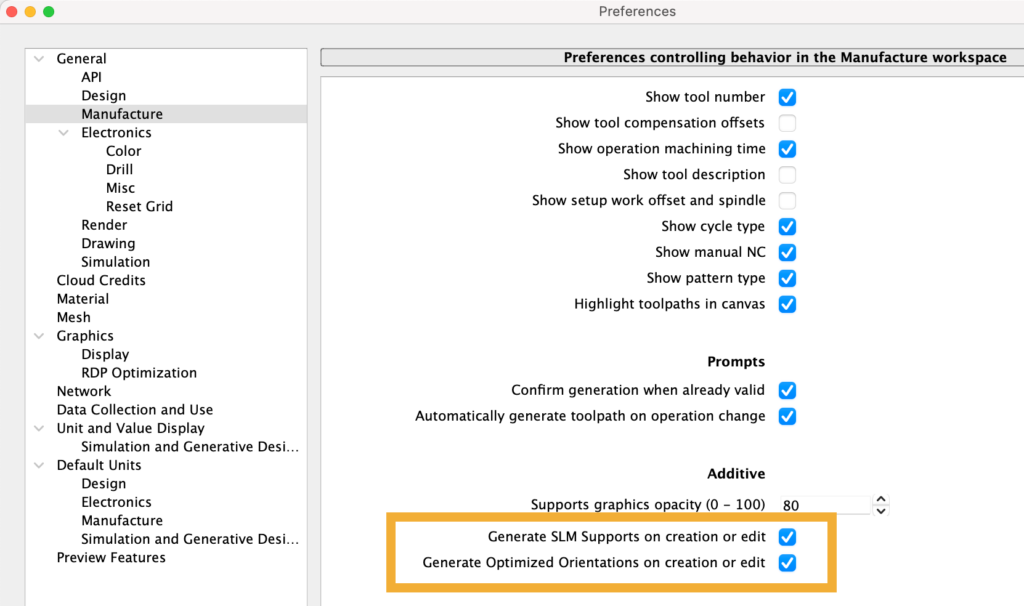
- In your preferences> General> Manufacture >Additive section, we updated the description of both Generate SLM Supports as well as Optimized Orientations so that they read better.
- FFF Print Settings dialog has been updated to include units for all relevant inputs.