
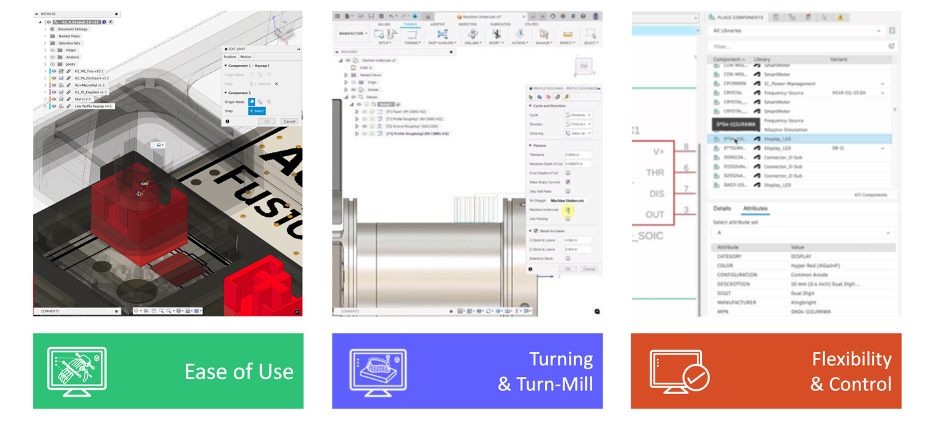
Discover powerful new features and enhancements in the Fusion March update, designed to elevate your Design, Drawing, Electronics, Simulation, and Manufacturing workflows.
v.2601.1.37 – April 30, 2025
Usability:
- We corrected the background color of the “Close Document (X)” icon on inactive tabs.
Sheet Metal:
- We have resolved an issue where part number properties were lost in Sheet Metal Flat Patterns.
Manufacturing:
- We fixed a crash issue that occurred when “Select Same Diameter” was chosen in the drill function.
v.2601.1.34 – April 17, 2025
- Several stability improvements have been made to address different crash scenarios.
- We fixed an issue causing Project creation in personal hubs to not work as expected.
- We fixed an issue where drawing files displayed red boxes instead of views after using the GAL (Get All Latest) command.
v.2601.1.29 – April 13, 2025
Usability
- We addressed a variety of crash issues.
Electronics
- We fixed an issue causing Via Properties to not work as expected after running QuickTune.
- We resolved an issue where buried, blind vias were exporting incorrectly, causing shorts in the generated CAM files.
Render
- We fixed an issue where rendering depth of field was not working as expected after the March release.
v.2601.0.90 – March 24, 2025
Backwards Compatibility Notice: This version includes changes that are not backward compatible with previous versions. To ensure seamless data sharing and collaboration, please update to the latest build.
Table of Contents
- Highlights
- Usability
- Data Management
- Design
- Drawings
- Simulation
- Electronics
- Manufacturing
- Fixes
- Join the Insider Program
Highlights
We’re excited to announce the latest Fusion March update, blooming with new features and enhancements to elevate your workflows. Let’s dive into some of the highlights from this spring release!
Data Management
- “Property Matches” Column in Search Results
- Home tab as Default Startup Experience for New Users
- New Advancements towards Fusion Data Vision
Design:
- Enhanced AutoConstrain
- Enhanced Joint Functionality
- DXF Export Improvements for Sheet Metal
- Improved In-Canvas Measure System
- Custom Default Units for Mass and Length
- Configure on the Fly Expanded Support
Drawings:
- New Edge Symbols
Electronics:
- Import SVG
- Designating a pin as Not Connected in the Schematic
- Pick & Place File Export Update
- Soldermask Default now set to “Auto”
Simulation:
- Expanded Injection Molding Simulation Material Database
- New Study Materials UI for Injection Molding Simulation
Manufacturing
- Enhanced Workholdings Library
- Probe Geometry Fitting Enhancements (Manufacturing Extension)
- Numerous Turning Enhancements
- Improved Move command in Additive Manufacturing
- Improvements to 2D Additive Arrange
Usability
Important OS support information after March 2025
As of this update Fusion will no longer fully support macOS 12 Monterey. To continue developing Fusion with the latest advancements, we must stay current and phase out support for older OS versions. We appreciate your understanding and thank you for your continued support.
Fusion’s Progress Bar Status Now reflected in the Windows taskbar
Have you ever wanted to keep track of Fusion’s progress bar while the app was out-of-view? Now you can. Fusion’s progress bar is now integrated with the Windows taskbar so that you can keep track of application progress even while the application window is minimized or obscured.
Data Management
New “Property Matches” Column in Search Results
Search results in the Home tab now include a “Property Matches” column. This new feature highlights the specific values that matched your search query, providing clear insights into why a particular file was returned based on component properties. If a design matches the Component name or Part number, the respective file will appear in the search results with the highlight in the “Property Matches” column.
Please note that this functionality became available on February 21, 2025.
Home tab as Default Startup Experience for New Users
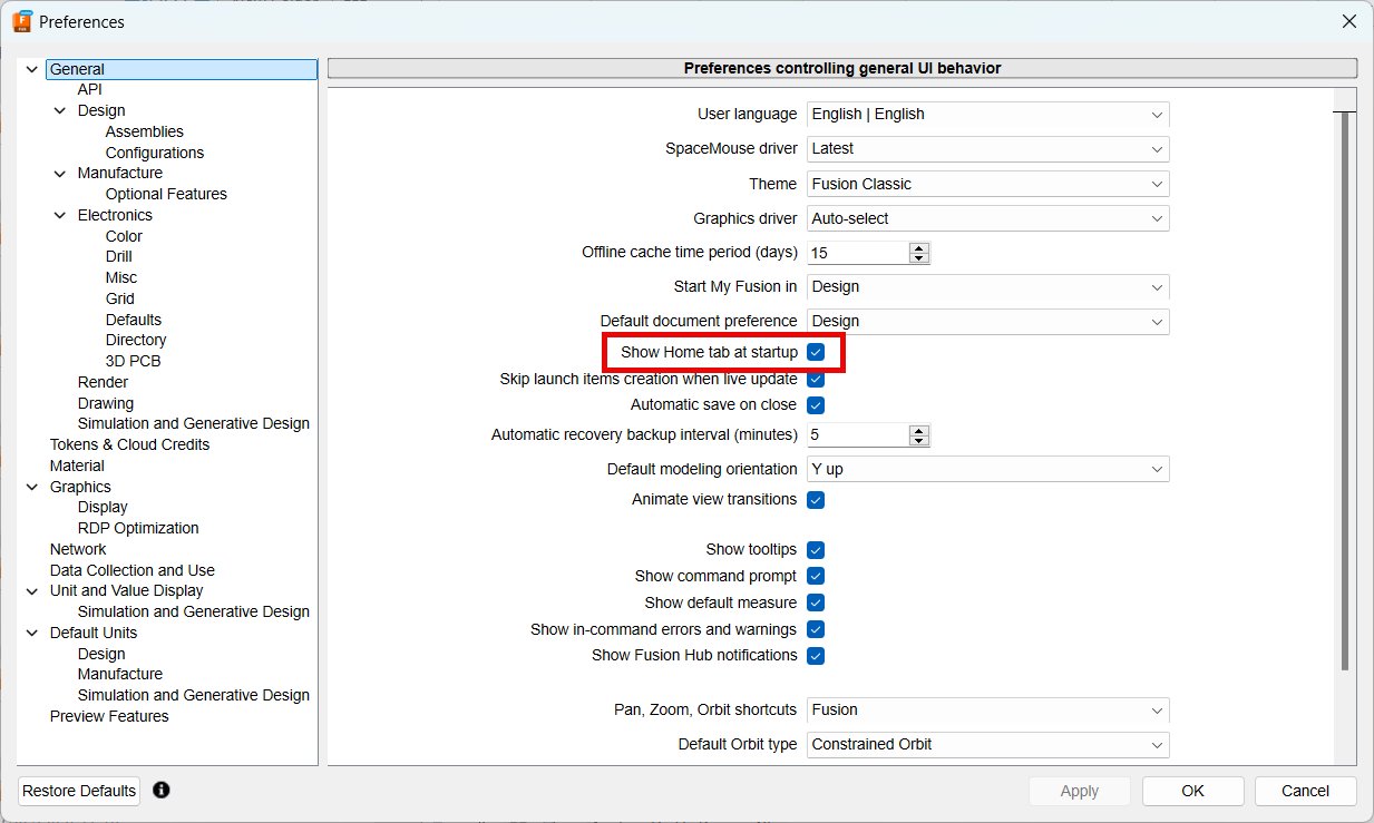
We’re excited to announce that the Home tab is now the default startup experience when you launch Fusion. This central hub allows you to easily view and access your data, and it’s available to all new users without a Personal (Single-user storage) hub. Designed to streamline your workflow, the Home tab provides a more efficient and organized way to manage your projects right from the start. If you prefer a different setup, you can toggle the Home tab off in the Preferences menu.
Export Fusion Files to Inventor 2024 files
Previously, you could only export files to Inventor 2022 format. Now, with our latest update, you can export your Fusion designs directly to Inventor 2024 format. This upgrade ensures you can benefit from the new features and compatibility in Inventor 2024.
Moving Toward a More Agile Product Development

Back in January, we shared in our Roadmap Update blog post that Cloud Data & Collaboration is one of our three key pillars this year. Today, we’re excited to dive deeper into our vision for Fusion data—why we’re moving in this direction, what a unified data model means, and the powerful new capabilities coming soon to enhance team collaboration. There’s so much to cover that we’ve dedicated a separate blog post to this topic.
To explore our vision and upcoming innovations in data management and collaboration, check out our deep dive here.
Design
AutoConstrain Enhancements
AutoConstrain is an AI powered workflow that will automatically add intelligent dimensions and constraints to sketches. In March we have added a number of improvements to this feature, starting with a slider to adjust the number of dimensions and constraints added, allowing you to step through each sketch element and to better understand what the AI has done.
We’ve also expanded the usability experience by supporting moving of dimensions with the command open and undo/redo of operations.
Enhanced Joint Functionality
We’ve made an improvement to the way Joints work. Previously, when editing a Joint, you couldn’t replace a selected component with another one that had a different parent component.
With this enhancement, you can now easily swap out any component within a Joint with any other component in your document, without any restrictions. This works with both referenced components and in EIP (Edit In Place) mode.
This enhancements allows you to configure joint snaps giving you greater control over position of components in configured assemblies. You can choose multiple options for each snap location of a joint and name each option as well as whether a joint is flipped or not for each configuration. Extra snap points can also now be spread across components
Learn more about Joints.
Enhanced DXF Export Control
With the latest update, you now have greater control over DXF exports from Sketch and Flat Pattern in the Sheet Metal workspace.
You can now select the units for DXF export according to your requirements, ensuring compatibility with different standards and preferences. Additionally, you have the option to choose specific entities for export, such as projected geometry, construction geometry, and points in a Sketch, as well as center lines and extent lines in a flat pattern.
These enhancements provide you with more flexibility and precision in managing both the units and contents of DXF exports, making the process more tailored to your needs.
Improvements to In-Canvas Measure Information
Selecting two connected curves now shows the combined length in the in-canvas information that is presented in the bottom right corner of the window. Previously this only worked for a single selections, or if there were more than 2 curves selected. Also, for multiple selections of different types of items, the total number of selected items is now displayed in the in-canvas information.
Customize Default Units for Mass and Length
Now you can set up your own custom units for mass and length, like displaying length in millimeters (mm) and mass in kilograms (kg). This can be done through the preferences page for design units, or from the document settings node in the browser, giving you more flexibility and control over how measurements are displayed in your projects.
Configure On the Fly Command Expansion
In the November release of Fusion, we introduced a Configure tab to some of the most-used modeling commands, making it easier to adjust aspects while modeling without interrupting your design flow. Building on this improvement from the January release, the March update continues to expand the list of commands supported in this workflow to include most of the Surface modeling tools.
When creating or editing a configurable feature, use the controls on the Feature tab as usual to define the feature. Then, switch to the new Configure tab, check the aspects you want to configure, and click OK to complete the command. Each aspect you checked is added as a column in the Configuration Table, allowing you to continue modeling without needing to switch contexts.
You can find the new contextual Configure tab in the following Surface command dialogs: Trim, Untrim, Extend, Stitch, Unstitch, and Reverse Normal. Stay tuned as we continue to support additional commands in future releases.
Learn more about Configurations.
Expanded Fastener Libraries
Apart from continuous improvements to existing families, we’ve introduced 27 new standard parts, including 7 entirely new items and 20 cloned items.
Key additions include various types of fasteners such as Hex Socket Button Head with Collar, Heavy Thumb Screws in different point configurations (Plain, Dog, Flat, Cup, Cone, Oval), Cross Recessed Oval Countersunk Head Tapping Screws, Cross Recessed Countersunk Flat Head Tapping Screws, and Plain Washers. These parts adhere to multiple international standards, including ISO, ANSI, DIN, NF, ČSN, PN, NS, UNI, SS, SFS, UNE, BS, and ASME.
These enhancements provide a broader selection of standard parts to meet diverse engineering requirements.
Learn how to insert a fastener.
Drawings
New Edge Symbols in Drawings
In Drawings, you can now define an Edge Symbol based on ISO 13715:2000 standard. Edge Symbols can be used to specify requirements around the processing and finishing of specific edges. They can be used to indicate the type of edge and its details with defined or undefined size and direction.
Learn more about Edge Symbols.
Simulation
New Study Materials UI for Injection Molding Simulation
Simulation > Injection Molding Simulation Study > Study Materials
We have been working on a new user experience for the Study Materials Selection dialog for Injection Molding Simulation study along with moving the injection molding thermoplastics material database to the Autodesk Platform backend.
You will see the new experience when you go to select a material for your Injection Molding Study. The new UI has almost all the existing capabilities like:
- List View
- Add/Remove and Sort Columns
- Search and Filter
- Favorites and Recents
- Material Properties Details View
- Search in Material Properties
Added Capabilities:
- Search Improvements: Improved search bar where you can quickly type the keywords you wish to search and the system will account for all of the keywords individually.
- Panel View: You can now see key properties of a selected material in a side panel in the Study Materials UI. You click “+” sign to expand and view property details for the respective categories.
Expanded Injection Molding Simulation Material Database
The Injection Molding Simulation material database just got better, giving you a more comprehensive database of both materials and manufacturers.
- Total number of New Materials added: 466
- Total number of Materials updated: 791
- Total number of Materials deleted: 73
- New Manufacturers added: 7
- Manufacturers deleted: 4
- New Total number of Materials: 13816
- New Total number of Manufacturers: 618
Electronics
Import SVG
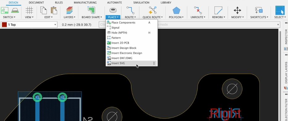
For some time, many of you have requested the ability to import SVG files into your electronic documents. Now, you have a straightforward method for incorporating a company logo or essential symbols that need to be included in your schematic or PCB. Importing SVG files into your design editor enables precise vector-based graphics for detailed silkscreen work and accurate logo placement, allowing for high scalability. This new feature will also function in the library document symbol and footprint editors.
Designating a Pin as Not Connected in the Schematic
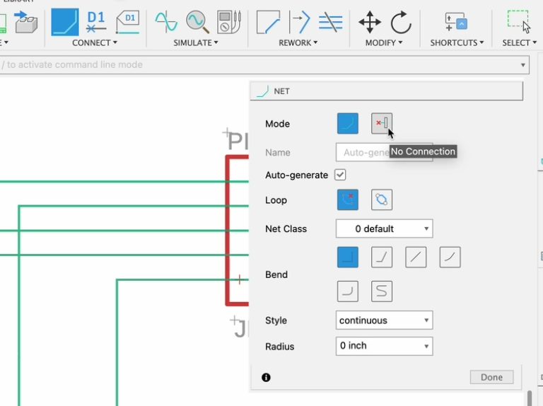
Flagging unconnected pins in a schematic prevents Electrical Rule Check (ERC) errors, ensures accurate netlist generation, and avoids unintended connections during PCB layout, improving overall design clarity. Previously, this capability was only available in the library document symbol editor; with this update, unconnected pins can now be flagged directly within the Schematic. This enhancement not only improves documentation and design workflow but also saves time by eliminating the need to mark unconnected pins as acceptable in the ERC report. Additionally, this action can be performed on a single pin or a selection of pins (via the design manager), ensuring greater accuracy and efficiency in circuit development.
Pick & Place File export update
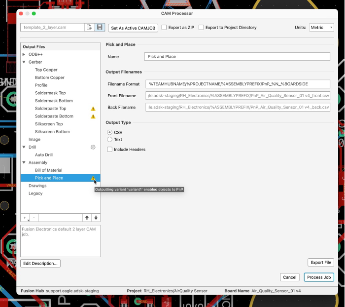
A Pick and Place (PnP) file is a manufacturing output file that contains precise component placement data for automated PCB assembly machines. It includes details such as component reference designators, X-Y coordinates, rotation angles, and part numbers, ensuring accurate and efficient placement of components onto the PCB. We are happy to inform you that the pick and place output can now include through-hole components (THT). In addition, the components not part of the assembly variant will not be included in the Pick and Place output. These new implementations will assist you in getting accurate manufacturing exports sooner.
Soldermask Default is now Set to “Auto”
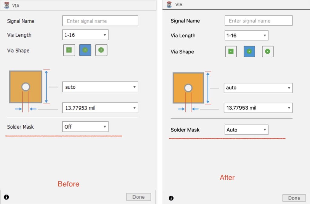
A via on a PCB allows electrical signals to pass between different layers, enabling complex multi-layer circuit designs. The solder mask on a PCB insulates and protects copper traces from oxidation, prevents solder bridging, and enhances reliability during assembly. Depending on the design requirements, Vias can be covered by the solder mask (tented) or exposed. We have facilitated a way for you to easily switch without changing the design rule. This feature update provides greater flexibility in your PCB design process, allowing for easy adaptation and reliability requirements.
Image Export command now Considers the Active Layer
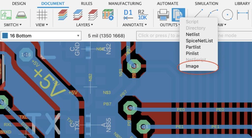
Exporting images of your PCB design is essential for documentation, design reviews, and effective communication with manufacturers and assembly teams. In this update, we have enhanced the image export functionality by prioritizing the active layer. This improvement will provide greater accuracy, making it easier for stakeholders to gain precise insights into the design.
Undo Layer Changes
While working with system (1-99) layers, you previously only had the option to restore default settings. In this update, you can undo your latest change without reverting to the default settings, providing you with more options when customizing colors and shades in your layer display panel.
Other Enhancements
- Improved SI Extension – Do not show signal wires over pads and vias
- Added appropriate error messages when attempting to flip locked components in 3D
- No more surge of RAM usage when switching tabs frequently
- After editing the base sketch of 3D PCB holes with reference dimensions, the 2D PCB is now updated correctly
- Library: Footprints with circles on the Dimension layer work as board outlines now
- New way to turn all rules on or off from the column header
- We have begun standardizing the attributes in our component libraries.
Manufacturing
Enhanced Workholdings Library
The Fusion configuration capabilities are now available for files in the Workholding folder. These are used when a single component is designed with multiple arrangements. Configured designs are applied to a single model number where it may be beneficial to capture multiple ways the part could be used. You can change the active configuration in the file by clicking on a drop down menu in the Browser design tree. We released these to simplify the existing vises in CAM Samples, making the model numbers more visible and the menus more streamlined, while still offering the same number of design arrangements for clamping simulation.
New Control for Importing CAM Data from Linked Designs
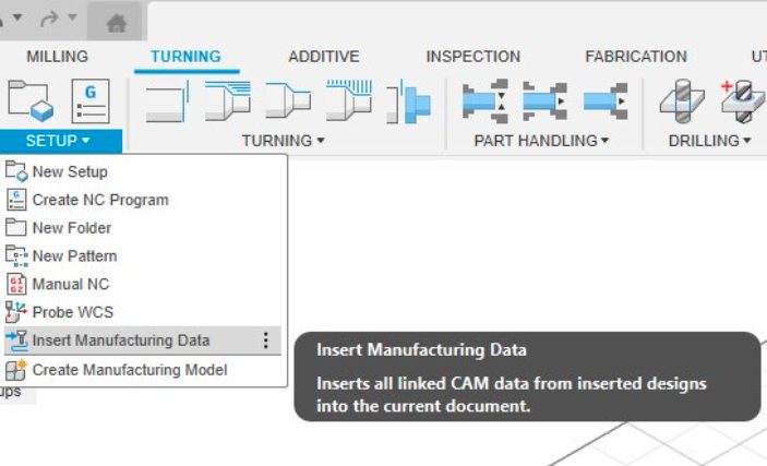
Since September 2024, you’ve been able to import CAM data from linked designs, making it easier to reuse CAM setups and operations. This is especially useful for positioning pre-programmed CAM parts in a vise or combining pre-programmed parts on a multi-part fixture.
Initially, you could only import CAM setups and operations when you first switched to the manufacturing workspace. Fusion would import the available CAM setups and operations from all linked designs, with the option to suppress them if needed.
We’ve now enhanced this functionality to give you more control over the import process. A new setup command allows you to import CAM setups and operations at any time. If you choose not to import them initially, you can do so later. The updated feature shows which designs have CAM setups and operations available, lets you choose which designs to import from, and indicates whether CAM data has already been imported from a design.
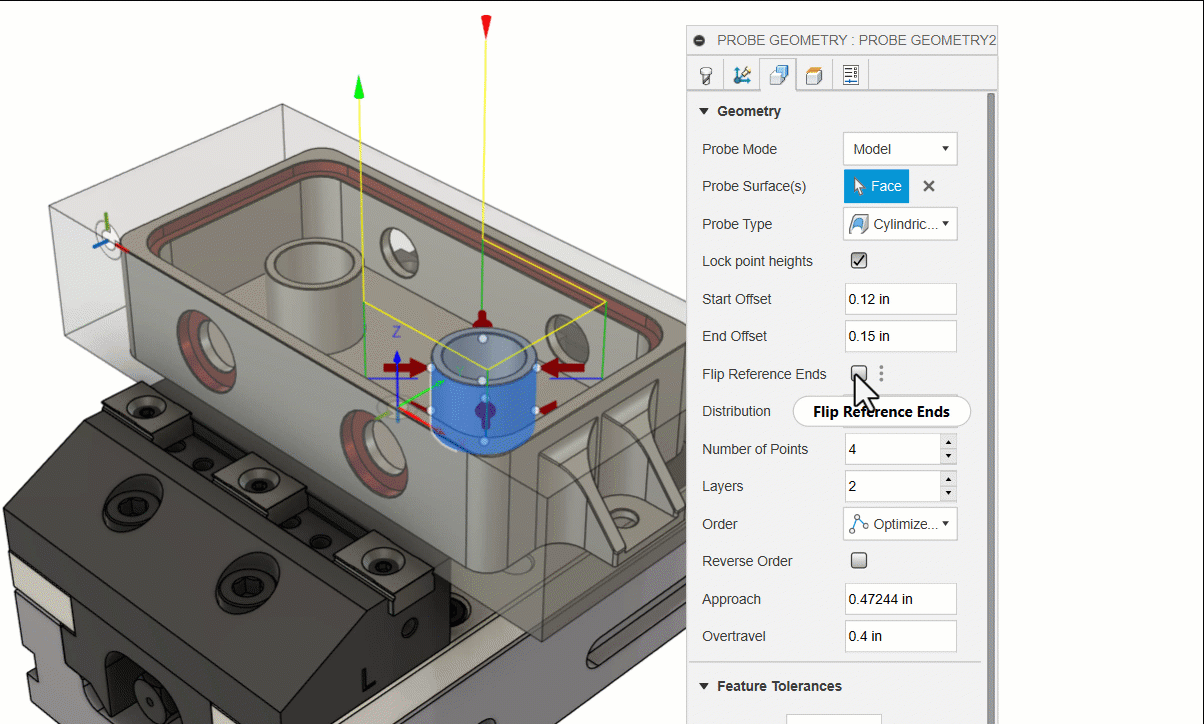
Probe Geometry Fitting Enhancements (Manufacturing Extension)
Probe Geometry supports the ability to fit circles, cylinders and planes to determine their circularity, cylindricity, and flatness. We have made two improvements to make the fitting functionality easier to use.
For cylindrical fitting there are ‘start offset’ and ‘end offset’ parameters for controlling the start and end heights at opposite ends of the cylinder. We have added a ‘Flip Reference Ends’ control to allow you to reverse the cylinder direction and change the order of the probed points.
For displaying the results of the probed points we have simplified the interface. ‘Below Tolerance’ shows out-of-tolerance points that are beyond the Lower Tolerance. ‘In Tolerance’ shows in-tolerance points that are between the Lower Tolerance and the Upper Tolerance. ‘Above Tolerance’ shows out-of-tolerance points that are beyond the Upper Tolerance.

Learn more about the Probe Geometry strategy.
Learn how to control the display of inspection results for geometric fitting.
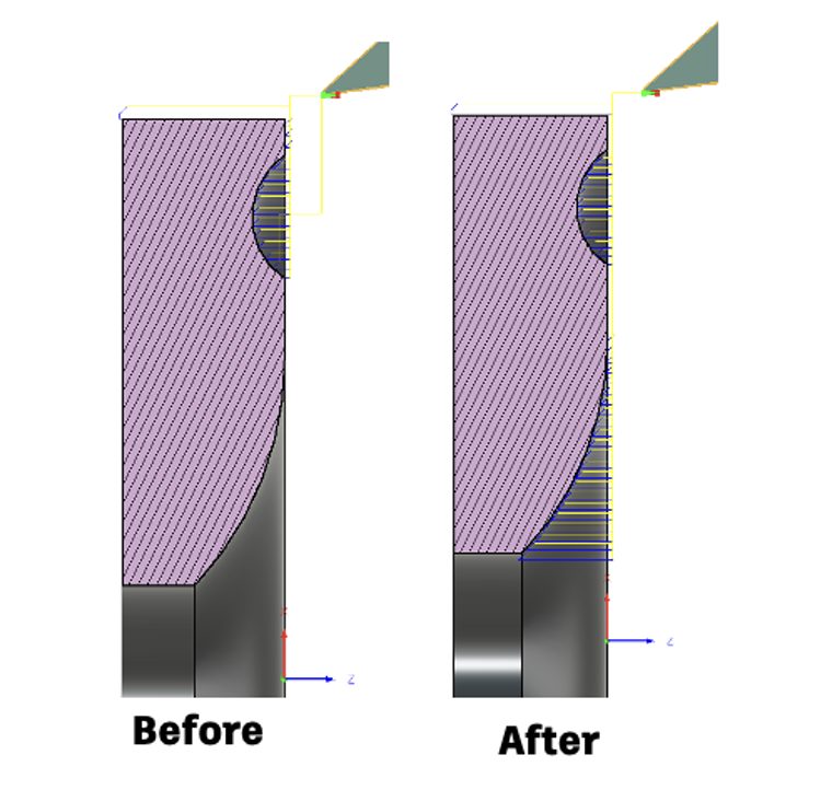
Turning
Profile Roughing and Finishing: New Parameter for Multiple Region Machining
We’ve introduced a new parameter for turning profile roughing and finishing toolpaths. This lets you choose whether to machine multiple disconnected OD/ID and face regions on your model. These enhancements are aimed at providing you with greater flexibility and precision in your machining operations.
Enhanced Control for Approach and Retract X Coordinates
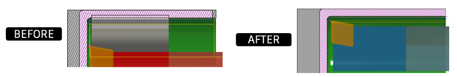
You can now specify whether Turning toolpaths start or end at the X coordinates of the start or end points respectively. This feature is a huge benefit if you’ve struggled to prevent the tool from retracting too far, risking collisions and costing precious time.
Profile Roughing: Allow Machining Undercuts
We’ve added the ability for Turning Profile Roughing to machine undercut grooves with ease, ensuring more precise and efficient operations. Additionally, we’ve added collision-check functionality for both the back of the holder and the back of the insert. This enhancement helps prevent potential collisions, safeguarding your tools and saving you time.
Want to Try More Amazing Turning Features?
Join the Insider Program for exclusive access to advanced turning functionality before it is released to the general public. Get insider access to new and emerging pre-release turning functionality and stay ahead of the curve with the latest innovations in turning technology. Don’t miss out on the value of previews and the opportunity to be at the forefront of turning technology.
Additive Manufacturing
Improved Move Command in Additive Manufacturing
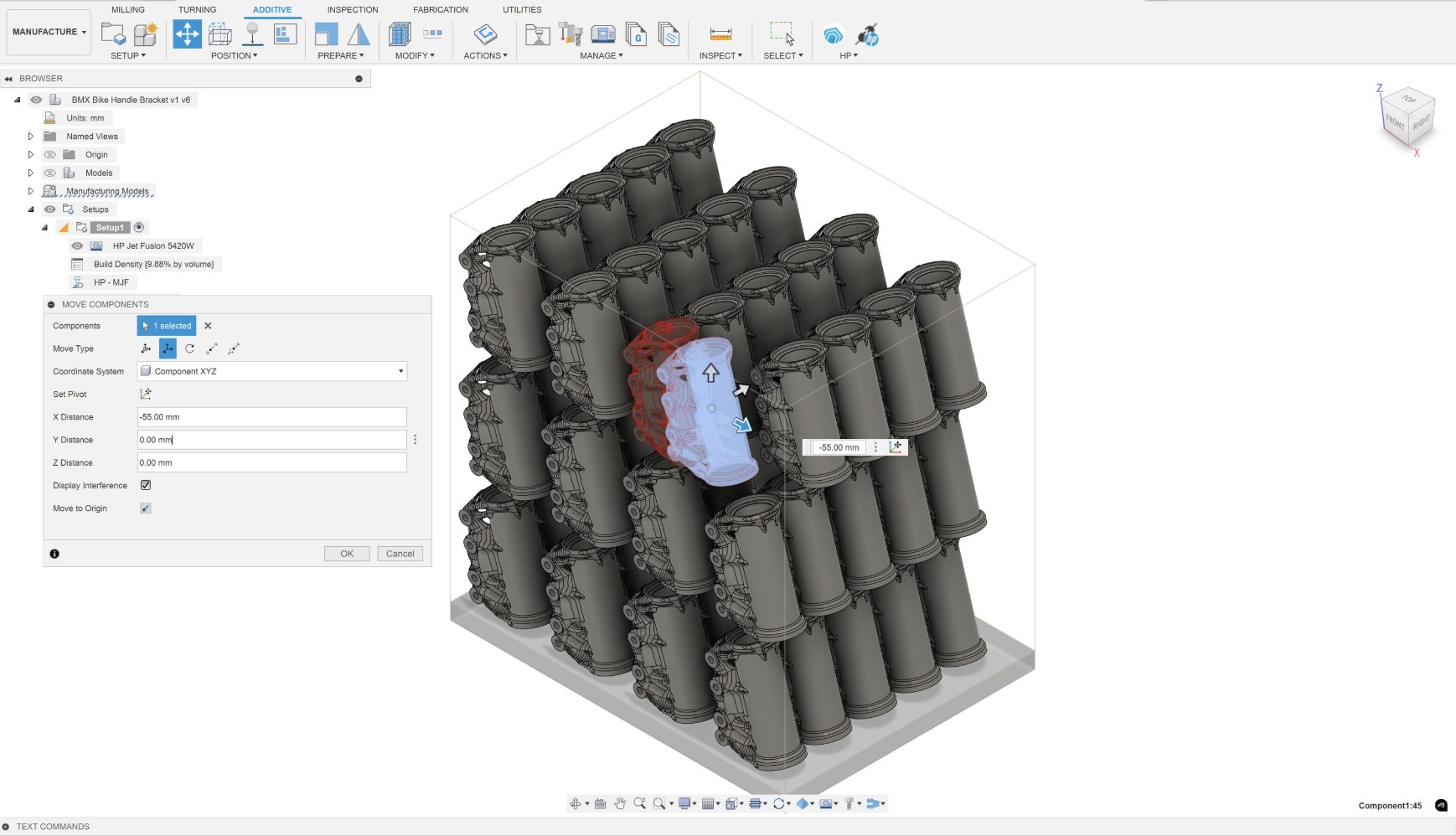
After creating an Additive Setup within the Manufacture Workspace, you can use the Move command to translate and/or rotate your components within the active Setup.
With this release, the Move command within the Manufacture workspace has been improved to match the move command located in the Design workspace and includes all the movement types (free move, translate, rotate, point to point and point to position) the move command in the Design workspace offers. The improved Move command now allows you to set a new pivot position for your selected components. You also have the option to display any potential collisions between components that may interfere with each other while moving them.
Learn more link about how to move or rotate a component in a build volume.
Improvements to 2D Additive Arrange
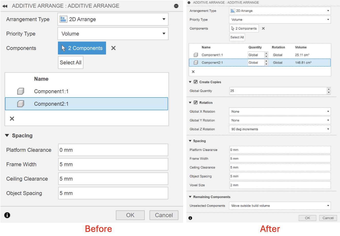
With this release, the Arrange command, which is accessible from the Position panel of the Additive tab within the Manufacture workspace, now utilizes the voxel-based True Shape algorithm when the Arrangement type is set to 2D Arrange.
The True shape algorithm has several benefits over the previous 2D nesting algorithm that was available in Fusion. With this change, the 2D arrange nesting outcomes will result in better part placement when packing parts in additive machines with no build zones. The True Shape nesting algorithm also allows you to control the rotation and the quantity of each part during the nesting process.
The updated dialog for 2D Arrange also displays the volume of selected parts in a table, which can be useful when you prioritize parts for nesting based on their volume.
With this update you can select the components you wish to arrange within the build area of your 3d printer and the unselected components can be locked in place or automatically moved outside the build volume of your machine. If you chose to lock them in place, make sure to pre-position them so that the outcome of the arrangement meets your nesting objectives.
Learn more link about how to arrange components for additive manufacturing.
New Post Processor and Machine Simulation
Looking for the latest post processors and machines updates? This March we released a ton of new updates and improvements to many of the open-source Post Processors and Machines we offer for free. Within this release you will find improvements to post processors including Generic Post Processors, Milling Post Processors, and Turning Post Processors. We also added new machines to our Machine Library, updated our Workholding library, and improved functionality around the Autodesk CAM Post Processor engine.
Learn what’s new for Post Processors and Machine Simulation this March.
Missed the February update? Learn what’s new for Post Processors and Machine Simulation from this past February.
Fixes
Regular updates and fixes are crucial to ensuring a smooth and efficient user experience. Addressing bugs and improving functionality helps eliminate frustrations, enhances productivity, and maintains the reliability of the software. With each update, we aim to make your workflow more seamless and enjoyable.
Forum Reported Fixes:
Your feedback matters to us, and we’re dedicated to improving your experience with every update. You’ve shared your thoughts, and we’ve listened and acted. Within each workspace our teams are constantly working to make your experience within Fusion as smooth as possible. If you haven’t already, now is a great chance to check out what forum reported issues we have addressed in the March update.
Check out what we fixed in Design.
Discover what we fixed in Manufacturing.
Recent Fixes:
- Non-visible Bodies in Assembly Contexts: We fixed an issue where non-visible bodies would incorrectly cxhighlight when the parent component was selected. Now, only the parent component will be highlighted, avoiding confusion.
- Fusion Splash Screen Display: We fixed an issue causing the Fusion splash screen to always appear on the primary display, even when Fusion was opening on a secondary display. The splash screen now appears on the same display as the app.
- Table Headers Visibility: We corrected the issue where clicking and holding the mouse on a command’s table header caused the row to blend into the background, making it invisible. The headers now maintain better contrast.
- [macOS] “Show Navigation Bar” Command: We fixed the issue where the “Show Navigation Bar” option was disabled after using “Hide Navigation Bar” in an Electronics library. The command is now correctly enabled.
- Canvas and View Cube Orbit State: We resolved an issue where the Canvas and View Cube could get stuck in an Orbit state if Update/Restart notifications appeared while orbiting.
- Component Browser Context Menu: We fixed the issue where right-clicking in the Component Browser showed the wrong menu. Right-clicking the visibility “eye” now opens the correct context menu without toggling visibility.
- [Windows] Input Lag with Active Stylus: We addressed input lag experienced with active stylus actions in the canvas, making pen actions smooth and responsive again.
Join the Insider Program
The Autodesk Fusion Insider Program enables you to access the next version of Fusion and all the new features, improvements, and fixes, 3-4 weeks before the general public. As a member, you’ll gain inside knowledge of when we are deploying an update, as well as a first look into what’s new and what’s coming next. You will also have the opportunity to join exclusive events, try pre-release functionality, and give feedback straight to the product teams.