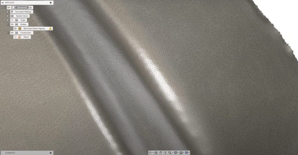
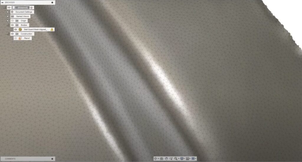
Let’s dive into how to work with STL meshes in Autodesk Fusion, including importing, understanding properties, remeshing, and more.
It’s crucial to understand that not all mesh files are created equal. A design created in a CAD program and converted to a mesh file will differ from one derived from a 3D scanner. Our focus here is on 3D scanner-based meshes, but most of the tips and techniques apply to all types of meshes.
Importing meshes
There are several ways to import a mesh into Fusion, but the preferred method is to use the ‘Insert Mesh’ option under the mesh tools. This allows you to open STL, OBJ, or 3MF files in Fusion. It’s important to note that STL files only contain triangular mesh elements, while OBJ and 3MF files can also contain quad meshes or n-gons. These files may also contain additional information such as material, appearance, and 3D printer settings.
Elevate your design and manufacturing processes with Autodesk Fusion
Understanding mesh properties
Once you’ve imported a mesh body into Autodesk Fusion, it’s crucial to check the Mesh Properties. The number of faces in the mesh body can significantly impact Fusion’s performance. To simplify this, you can make the mesh body unselectable. This makes rotations and movements in the Canvas area much quicker.
Remeshing and smoothing
If your mesh file is large, you may need to remesh it to reduce the mesh count. Fusion provides two main tools for this under ‘Modify‘: ‘Remesh‘ and ‘Smooth’. Remeshing changes the size of the mesh elements based on your settings, while smoothing adjusts the angles between adjacent faces, making filleted corners appear flatter.


Using mesh section sketches
One way to recreate a mesh-based design is by using mesh section sketches. By selecting the body and creating a section sketch, you can fit curves to mesh sections. However, this process can be tricky and requires a clear understanding of the design intent. For instance, if the original design contains straight lines, you may want to use the straight line tool to recreate those sections with straight lines.
Creating a freeform body
Another approach is to create a freeform body. By using the ‘Create Form’ option, you can start a freeform body using the face tool and Object Snap. This allows you to snap directly onto the mesh body and use the ‘Edit Form’ option to continue modeling the design, following the curvature of the design.
Converting a quad mesh to a t-spline body
If you have the product design extension, you can convert a triangular mesh to a quad mesh and then to a T-spline body. This process involves using the ‘Convert’ option under Utilities, selecting ‘Convert type quad mesh to T-spline’, and choosing your quad mesh body. This results in a quad mesh T-spline body, which can be manipulated and adjusted as needed.
Working with STL meshes in Autodesk Fusion can be challenging, but with the right tools and techniques, you can effectively create high-quality designs based on scanned or reference meshes. Whether you’re creating mesh section sketches, freeform bodies, or converting quad meshes to T-spline bodies, Fusion offers a range of options to suit your needs. Always remember to experiment with different workflows and settings to achieve the best results for your specific project.