
Usability
New! See your Fusion 360 designs in augmented reality with USD file format
File > Export > .USDz format , open in your iOS or mobile device
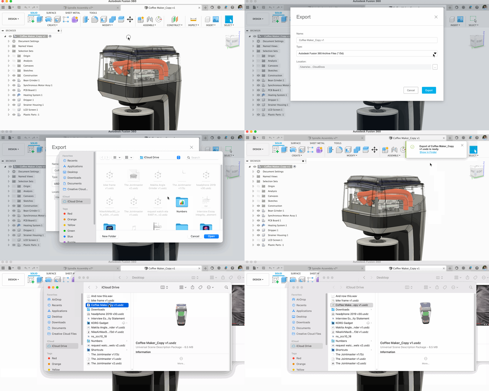
Augmented reality has been around for quite some time now, but adoption of the technology has been slow. You can see some examples of AR applications in online shopping, and now we’re pushing the industry forward with making it easier to see your Fusion 360 designs in AR via your existing mobile devices.
Now in the File > export options, you’ll be able to export your designs as USDz format. Originally developed by Pixar and now supported by Apple, Nvidia, Houdini, and Blender, USDz is a 3D file format that shows up as AR content. It’s rich in detail, optimized for storage and sharing, and is part of a WebAR viewers that allow seeing Augmented Reality preview on both iOS and Androids. Currently, devices with iOS 12 and above can view USDz files natively.
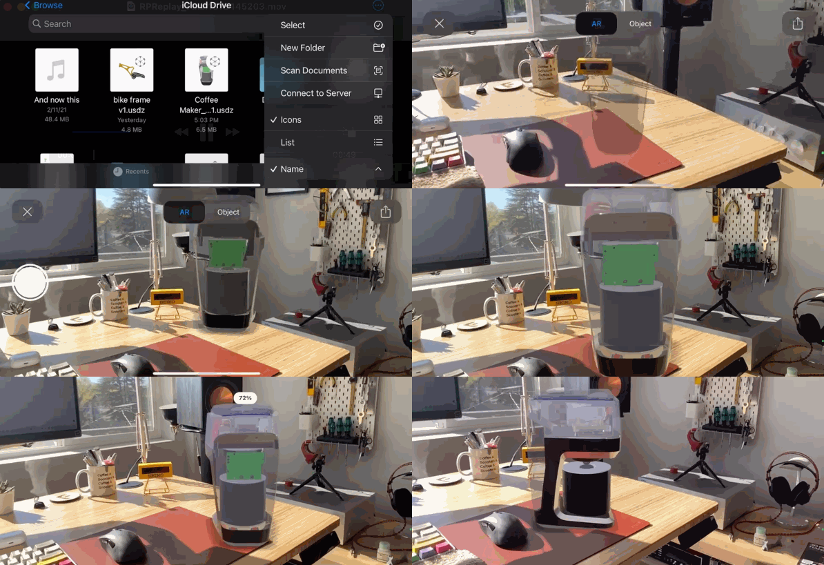
Exporting your design into your iCloud folder enables you to retrieve it from your iPhone or iPad and immediate view your design in AR. The benefits here are clear – you can immediately get a sense of the scale of your design and see in a real-life environment. AR makes it easier for you to communicate your designs with others, speed up decision making and reduce potential operating costs. Oh yeah, and it’s just plain cool too.
Note: there are a few things to be aware of that may impact your experience. Check out the Known Issues forum thread for details.
Improved! Fusion 360 Learning Panel is now better than ever
Help Menu > Learning Panel (English Only)
The learning panel in Fusion 360 has come a long way, and we’ve made a ton of improvements to it to provide better guidance for the vast majority of the commands in-product. To access, click Show Learning Panel from the Help menu in the top right corner. As you click on commands, the content in the panel updates to show content for the current command. Also, if you hover over a command long enough for the tooltip to appear, click ctrl+/ (cmd+/ on Mac) to open the panel with content about the command.
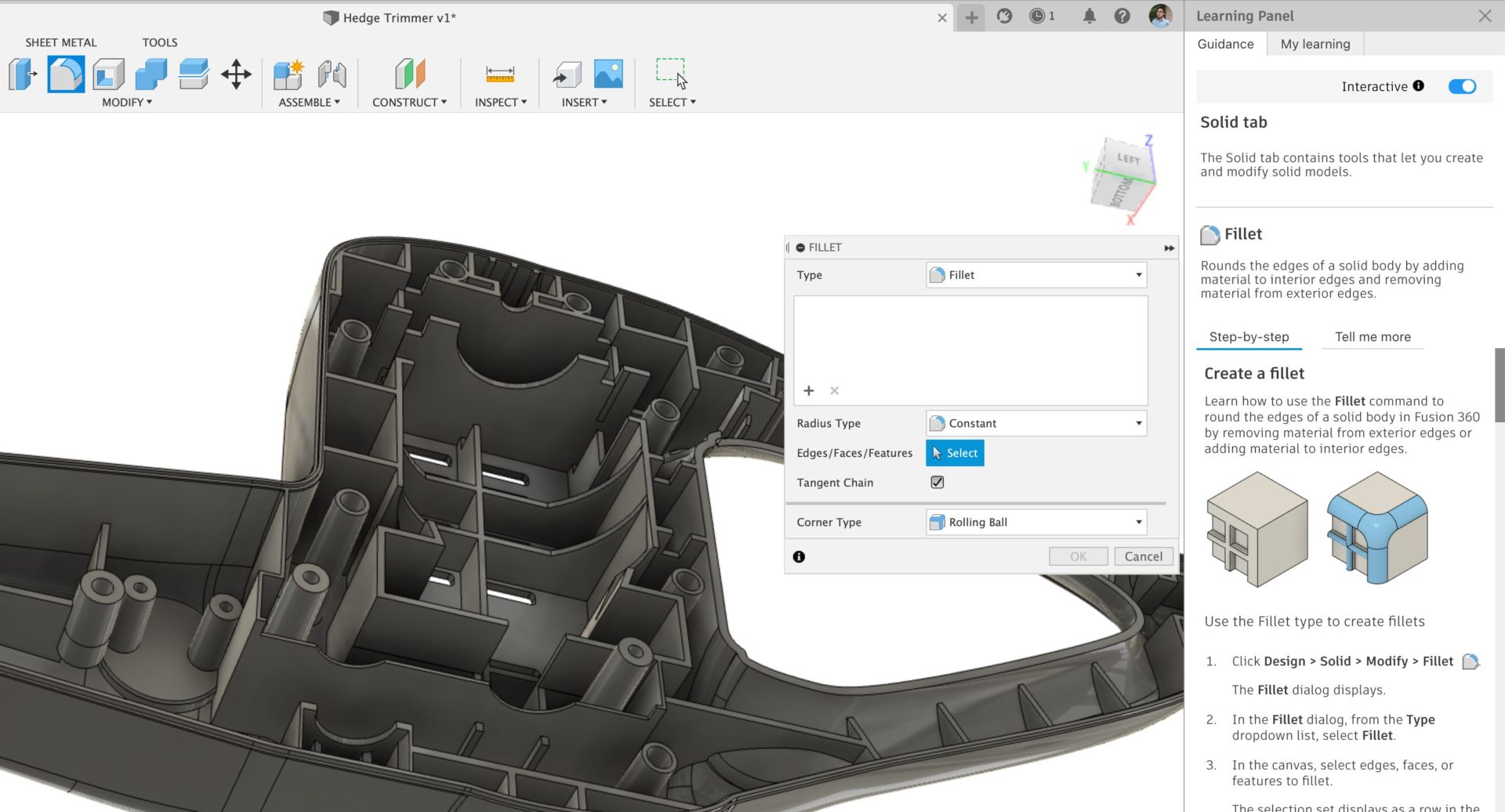
When originally released a few years ago, the Learning Panel delivered tips and tricks and helpful suggestions in response to user actions. This new aspect is that the Help content is piped in directly into the panel, appearing contextually based on the active command. All of the content in the “Guidance” tab is from the Help. The content in the “My learning” tab is the responsive content that was part of the initial deliverable.
New! More learning content for Fusion 360 Extensions
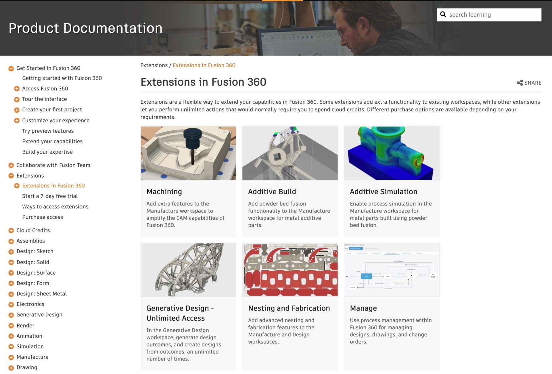
With Fusion 360’s extensions increasing in popularity, we’ve enhanced the learning content available to get you started using the extension capabilities in your design and manufacturing processes. A new Extensions page in the online help, shows the current range of extensions, and clicking on each extension takes you to more detailed information about that extension.
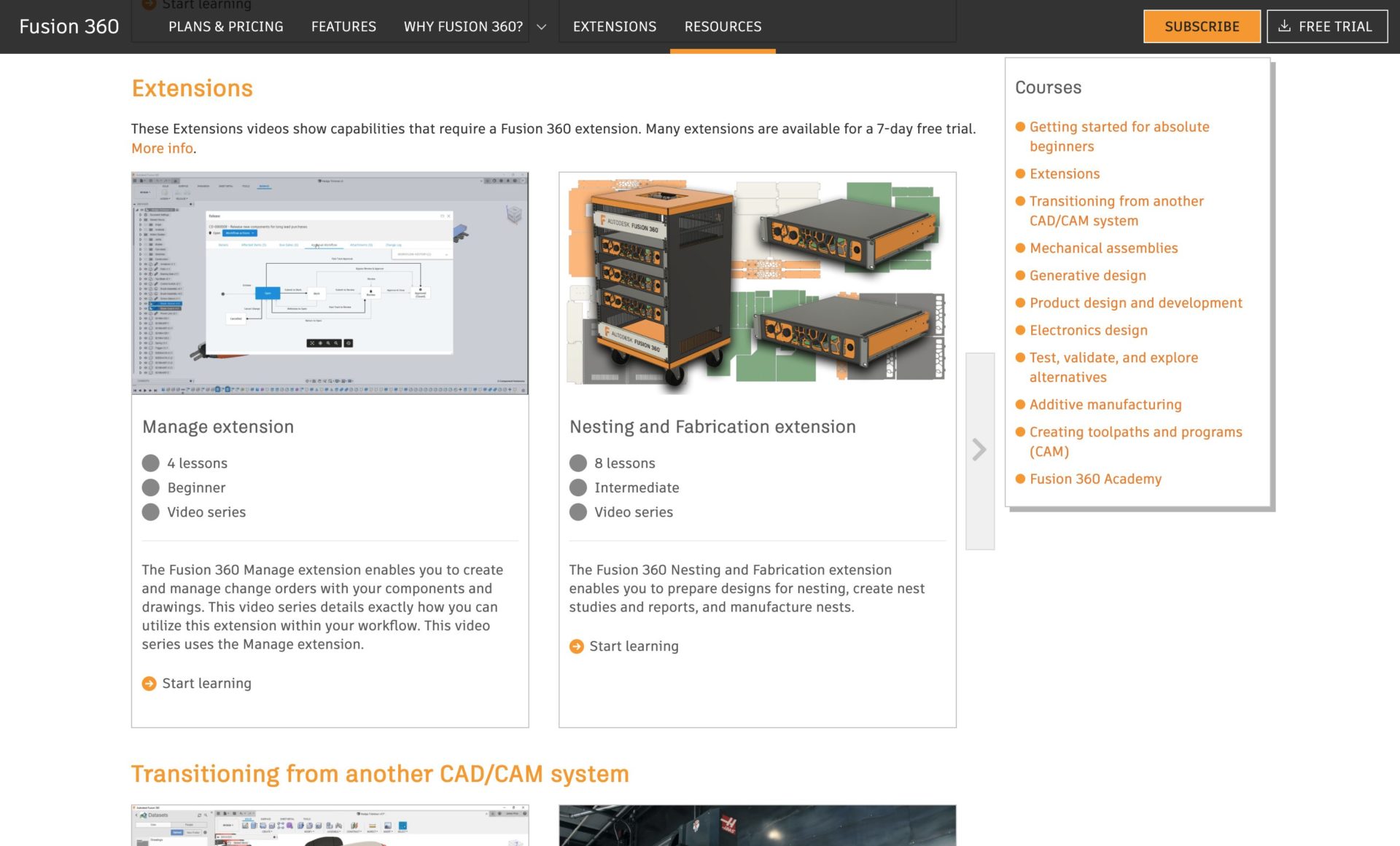
A new, dedicated Extensions learning path is now available to the Fusion 360 self-paced learning site. Here you can find video-based content demonstrating how to use extension capabilities in your design and manufacturing processes. We’re continuing to add new extensions-related content so do keep checking back regularly for updates!
Sketching & Modeling
New! Analysis tab in various modeling tools
Solid > Sweep and Surface > Sweep, Patch, Ruled, and Extend tools
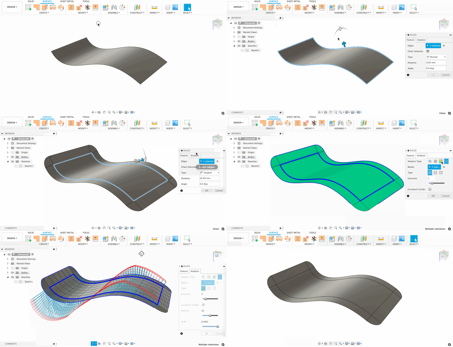
Now when you use the Solid > Sweep, Surface > Sweep, Surface > Patch, Surface > Ruled, or Surface > Extend modeling tools, you’ll see a new Analysis tab in the command dialog. The Analysis tab gives you direct access to some of the relevant visual analysis tools, so you don’t have to go hunting for the right one in the Inspect panel.
Learn more about Analysis tools.
Improved! Text Height is now an editable parameter
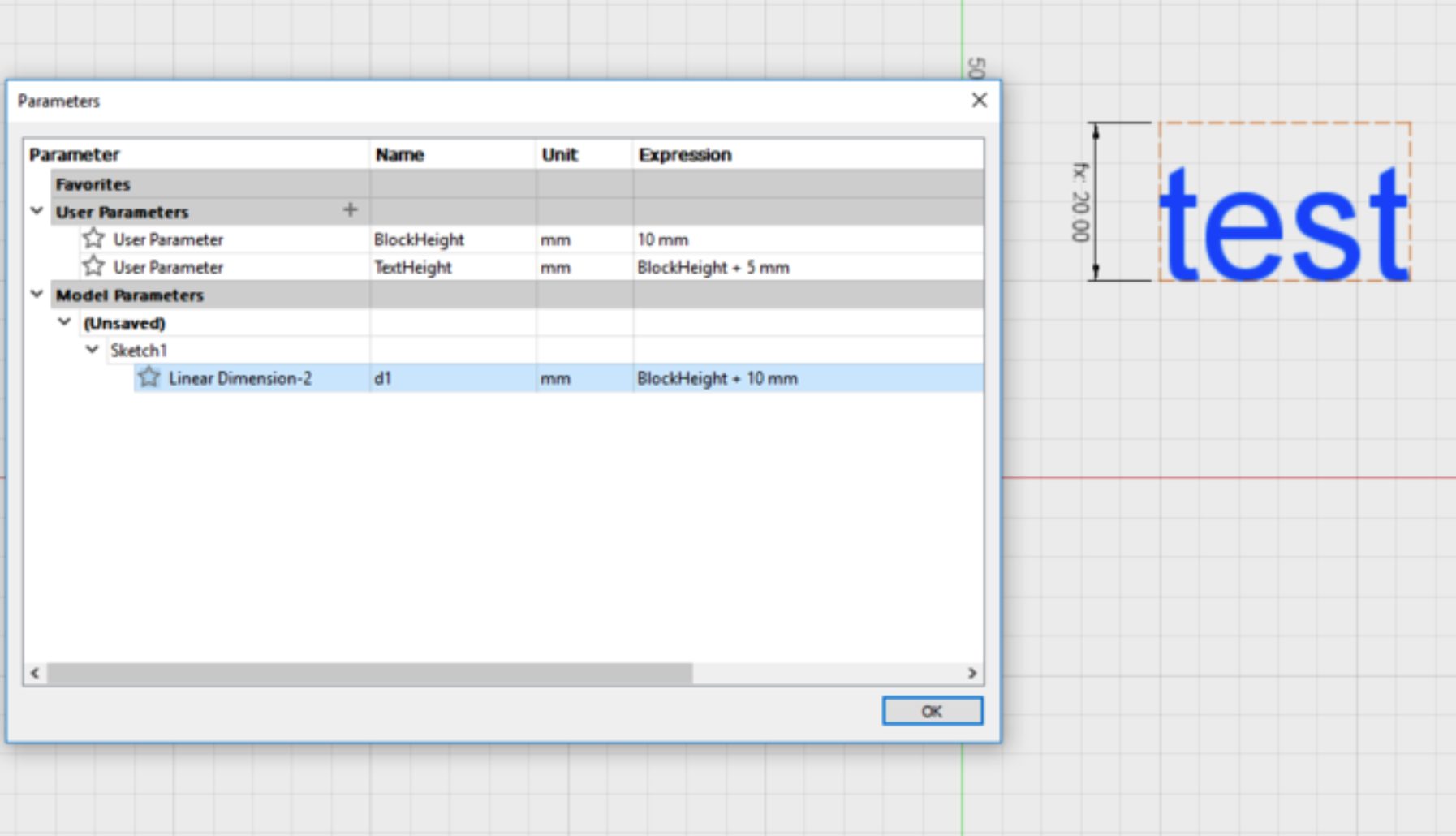
Good news! You can now manage your sketch text height and text block height as editable parameters in the Parameters dialog. This gives you more control and configurability over your use of Sketch Text.
Improved! Auto-fit window after scaling sketch on first dimension
Works only if “Scale entire sketch at first dimension” is turned on in Preferences
The preference option “Scale entire sketch at first dimension” enables you scale the entire sketch when you place your first dimension on it. If you have this option turned on, than you’ll be glad to know that Fusion 360 will also Auto-fit the window to sketch after it has been scaled on first dimension. This should make it easier to see the sketch as a whole, if your scaled sketch turns out to be bigger than your viewing area, or conversely too small for your viewing area.
Improved! T-Spline performance on bodies with high face count
Some of you working with Generative Design outcomes that have a high number of faces and edges will be happy to know that we’ve tweaked the T-Spline engine and increased its compute speed. This especially improved the workflow of freezing a T-Spline model with 20k+ faces at the preserved boundaries. What used to take a few minutes now takes seconds. Other tasks like enabling vertex selection filter in Edit Form, deleting a T-Spline edge, starting the Flatten command, and Unfreeze now all work much faster.
Electronics
New! Stop Mask support in 3D PCB
File > New Electronic Design > PCB > 3DPCB

While working on a PCB you will often hear of the Solder Stop Mask. The solder stop mask is part of the final process when making a PCB. The thin lacquer-like layer is a polymer that is applied to the copper traces of a circuit board for protection and stop bridges from forming on closely spaced parts. With this latest update, you have the option to push your PCB to 3DPCB with Solder Layer Geometry. This will provide you with a realistic look of your PCB which can help you notice unwanted bridges.

New! Display Dialog
File > New Electronic Design > PCB
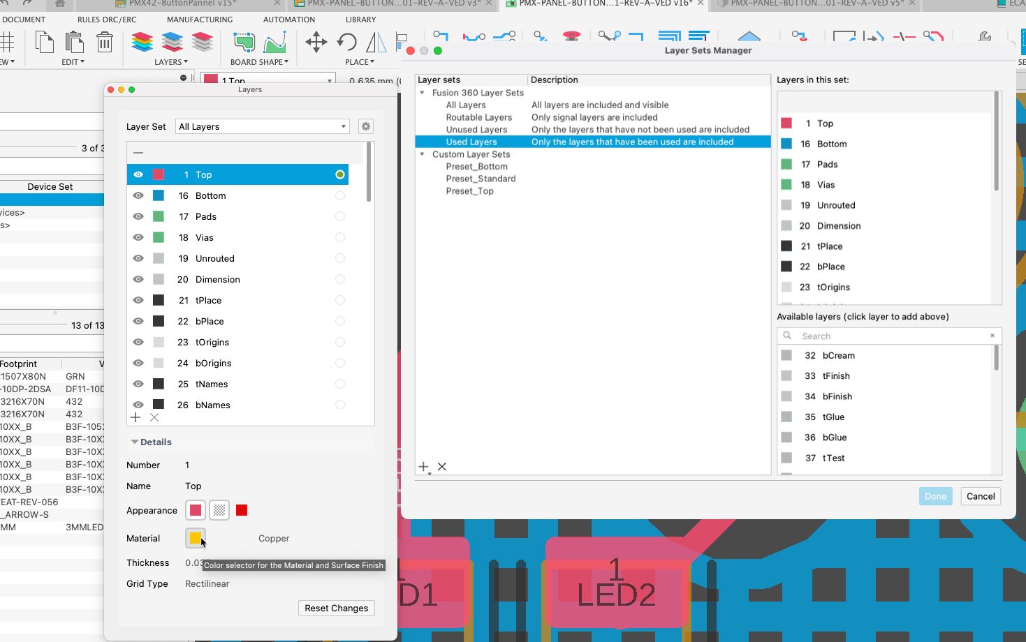
Next time you use the Display command, you will be pleasantly surprised by its updated interface, new material, and color options. The new UI now includes more functionality and versatility to speed up your design time. With the active layer indicator, you can be assured which layer is currently being worked on while making changes. The layer assigned color is now explicitly set to the layer and not to a pallet. This will avoid those situations in which changing a layer color would also change many other layers since they were all referring to the same pallet. The material option works the same way as it does in the CAM preview dialog. Here you can set the color of the material that will be reflected in the 3DPCB and in the CAM preview dialog.
During a PCB layout, you will constantly be hiding and enabling layers to declutter the working area. You can now keep the display dialog open while working on the design, since it nearly behaves like a panel. If you are working with multiple monitors, keep it available on one of them and change views faster. With the new Layer Setup Manager, you will be able to swiftly define and use layer combination pre-sets.
New! Receptacle header type
File > New Electronic Design > Schematic
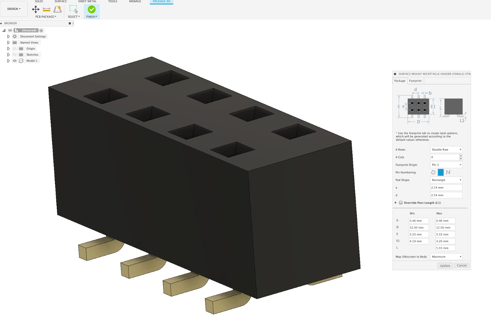
In this latest update of the library editor, you will notice that a new template has been added to the package generator for SMD (Surface Mount Device) Header receptacle. This connector is often used to connect ribbons that transfer a signal to different product areas or for programming. Now Fusion 360 electronic users will build this handy connector, and footprint is a matter of moments.
New! Package on Timeline
File > New Electronic Library > Package Editor
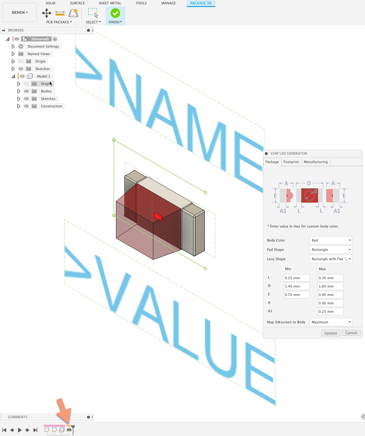
The building block of all electronic designs revolve around the available components required for the design. The repository components available in Fusion 360 are extensive, but there will always be parts you will need to create. The package generator makes it quite easy to build footprints and 3D models by simply transferring the mechanical values from the specification sheet into a template. If making changes to the component properties are required, you again look to look up the template. In this new update, the package now appears on the timeline, by simply double clicking it, you get immediate access to the used template ready for your updates. The new time saving feature will have you building and modifying parts with minimal effort.
New! New library parts
File > New Electronic Design > New Schematic > Add part
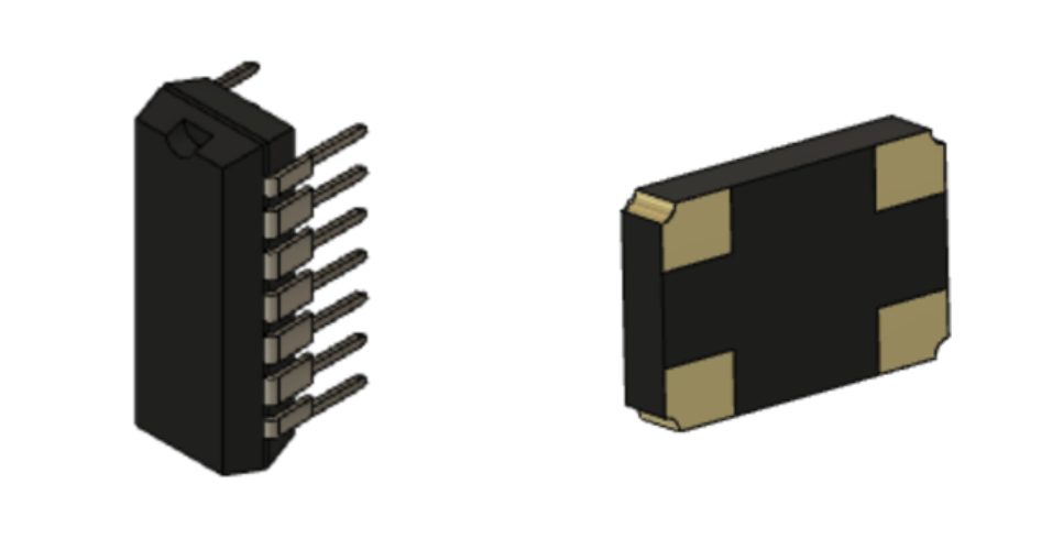
We have added new Micro-controller parts from ATtiny, ATmega series to IC_Embedded library and also the popular crystal oscillator parts to Frequency–Source library.
New! Loop Removal and Backspace support in Schematic
File > New Electronic Design > Schematic

As you are already aware, defining connections in a schematic is made by using the NET command. This process is not hugely different compared to routing a PCB, so why not include some of the routing features on the schematic? Glad you ask. Our developers have now adopted some of the routing capabilities available in the PCB into the schematic editor. The loop removal feature gives the option to replace or keep the current routing path. In addition to loop removal, use the backspace to undo prior mouse clicks, just as you do on the PCB. These routing capabilities in the schematic will exponentially optimize your design time.
Generative Design
New! Transparent View in Explore
Generative Design > Explore > Display > Transparent View
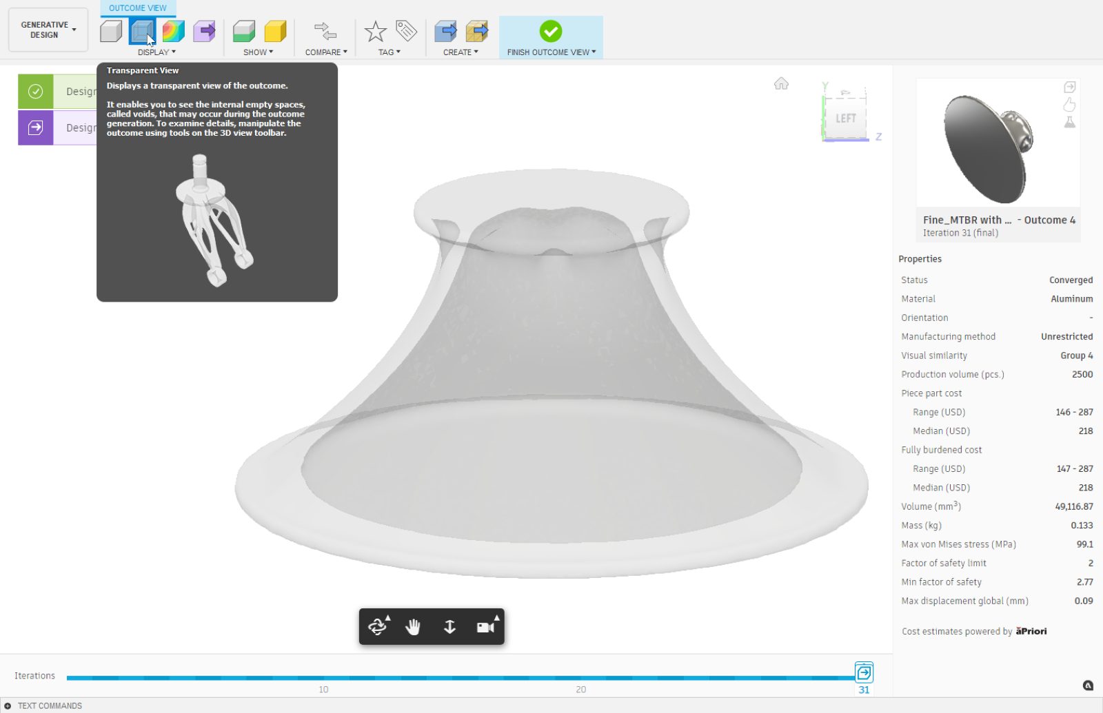
As we continue to evolve our Generative Design technology, the solvers are now starting to create internal voids were appropriate to create the highest performing shapes. To support better evaluation of outcomes, we have added a Transparent View option in Explore. This view option will help you see when voids are present in an outcome before opening the outcome in the Design workspace.
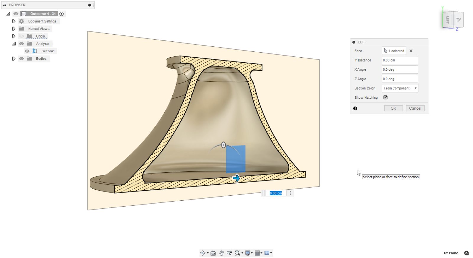
Learn more about Transparent View.
Improved! Expanding MFG Constraint Support in Experimental Generative Solvers and Features
Generative Design > Preferences > Preview Features > Experimental Generative Solvers and Features
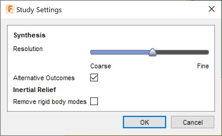
The Experimental Generative Solvers and Features preview has continued to mature and is now offering support for 2-axis cutting, 2.5-axis milling and additive manufacturing constraints. To obtain these outcomes, ensure that you have enabled the Experimental Generative Solvers and Features Preview and have turned on Alternative Outcomes option in the Study Settings.
Manufacture
New! Support for Formlabs SLA 3D Printers
Manufacture > Additive tab > Machine Library
Stereolithography (SLA) is the latest 3D printing technology to be formally supported by Fusion 360. SLA printers from Formlabs can produce high-resolution parts that are can be used for rapid prototyping or low-volume end-use production. You can now place your components in an additive manufacturing setup and select an SLA printer from Formlabs within the Machine library dialog. After orienting your components, you can generate support structures using one of four standard* support types that are now available for all users. Once you are ready, you can export your Fusion 360 Additive Setup as a “.form” file and open it within the PreForm software from Formlabs and proceed to printing your models.
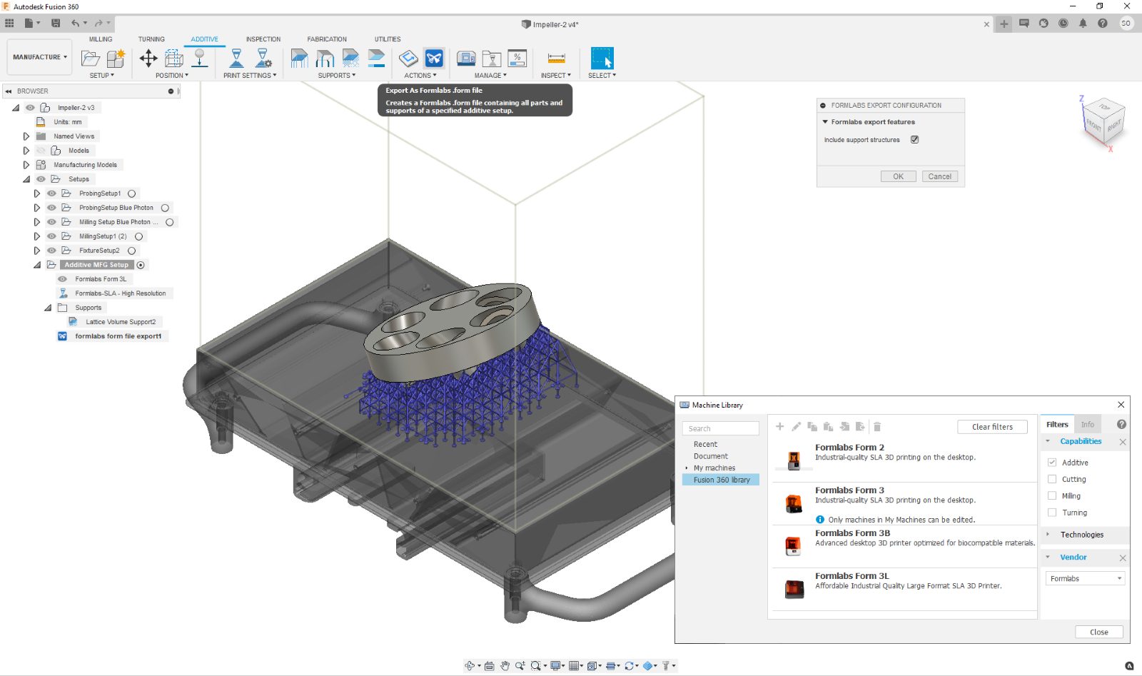
The integration of Formlabs printers into Fusion 360 will enable you to capture both your design and manufacturing intent in one platform and streamline your workflow specially when used in combination with existing functionality such as “My machines” within the Machine library dialog, customized print settings associated with those machines, additive setups you can create from templates that include orientation and support structure criteria.
*If you have access to the Additive Build Extension, you will have more options to generate advanced support structures which are commonly used in metal 3D printing.
Learn more about exporting an additive build to a FORM file.
Check out how Fusion 360 and Formlabs is a partnership made in heaven.
New! Support for SLM Solutions 3D Printers
Manufacture > Additive tab > Machine Library
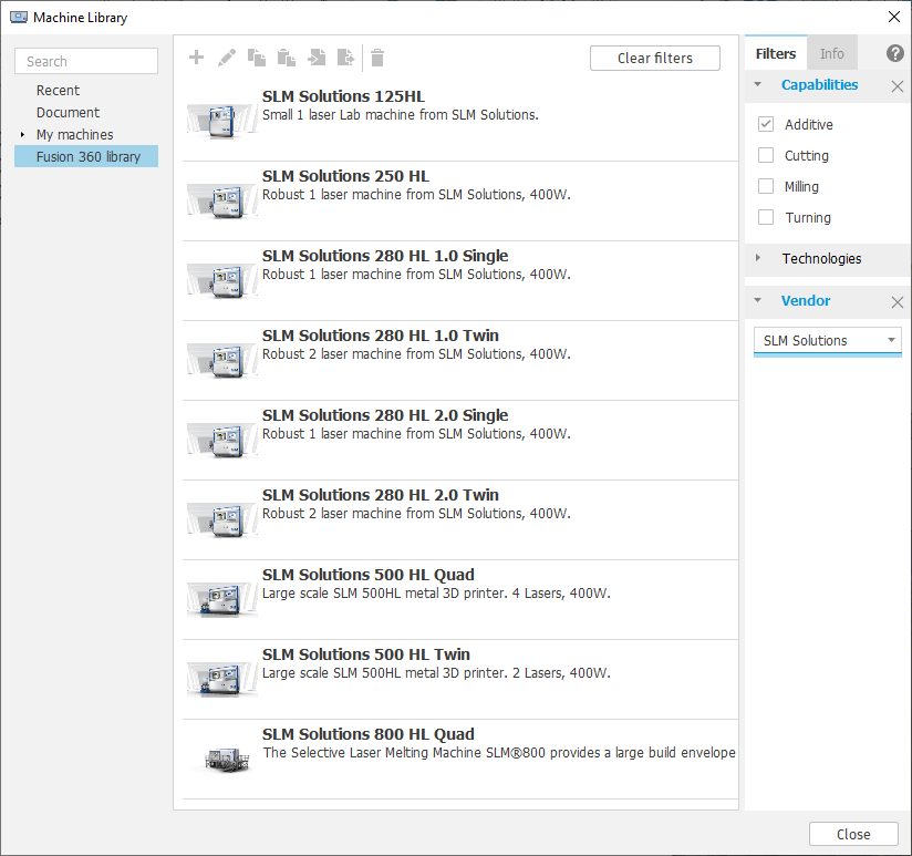
Metal 3D printers are available to users who have access to the Additive Build Extension. With this release you can now setup your models to be 3D printed on an SLM Solutions machine. You can choose from our library of print settings and customize them to have better control over your additive strategy. After orienting your components and adding the necessary support structures, you can generate the additive toolpath and create the necessary build file for your printer (*.slm file with or without a *.json Log file).
Improved! Thumbnail Images for all the Ultimaker 3D Printers
Manufacture > Additive tab > Machine Library
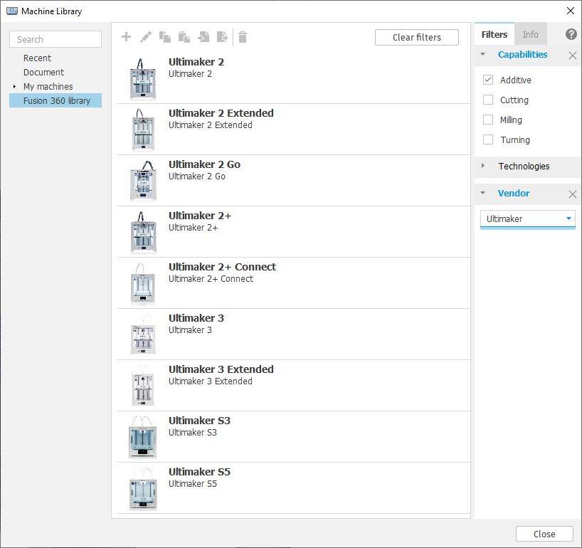
No more generic 3D printer images in the Machine library. Thanks to our partner Ultimaker, we can now display the official thumbnail images for all the Ultimaker 3D printers directly within the Machine library making it easier to select your printer when creating an Additive setup. Woohoo!
New! Keep Both option in Toolpath Trimming (Machining Extension feature)
Keep Both is a new option in Toolpath Trimming. Before this, you could keep inside or outside. Now you can keep both if you want. Keep Both is useful because You may want to separate regions of a toolpath for the purpose of reordering. If you split a toolpath into 2 pieces, then you can reorder it so the 2nd part goes before the first half (of the original toolpath).
New! Change Tool Modification
You may want to use a different length tool on part of the toolpath. So after splitting, you can now use the new Change Tool modification. This allows you to use a tool of different length, or a different holder assembly. The tool you change to must have the same cutting geometry. So if you start with a 10mm ballnose, you must change to a 10mm ballnose. But it might be longer, or have a different holder.
The Change Tool modification can work on any toolpath, trimmed or not. As described in the previous point, the tool you change to must have the same cutting geometry, but the length or holder assembly can be different. The main benefit of this, is that the toolpath does not need to be recalculated after a change. This option is typically used on large parts, or on toolpaths with long calculations as it can be a very fast way to change to a more suitable tool.
New in Preview! Machine Simulation
Preferences > Preview Features > Machine Simulation

Machine simulation is now released as a preview feature! This enables you to animate programs on your machine tool to see how it will perform, prior to physically running it on the machine tool. Unlike many other systems, our machine simulation is driven directly from the post processor so you can be confident that the solutions shown on screen will be what happens on your machine tool. We have made this as simple as possible to use, all you need to do is select a ‘simulation ready’ machine on your setup and click the ‘simulate’ button. If all is setup correctly, machine simulation will load up! If there are any issues whilst trying to run simulation, you will be shown a message and regular tool-path simulation will be started.
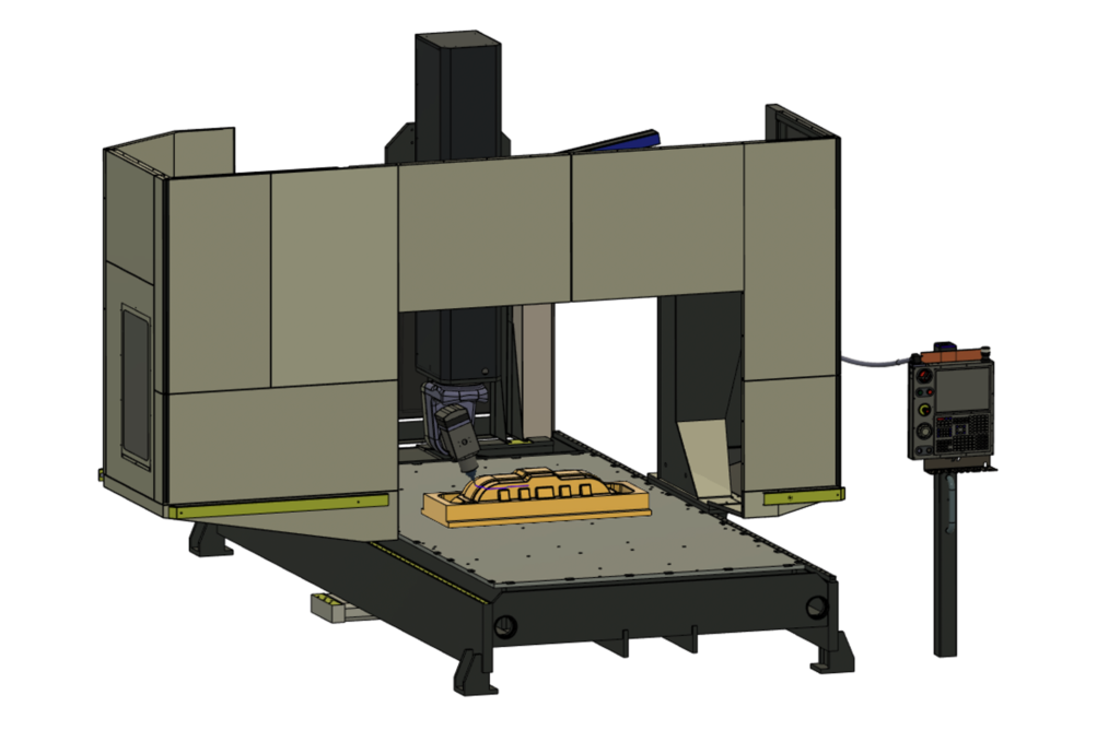
With this release, we have included a large library of simulation-ready machine tools in the Fusion machine library, here you will find machines from HAAS, HURCO, Matsuura and Tormach. If you don’t see your machine in our library, don’t worry, we have developed another feature ‘machine builder’ that allows you to get your machine into simulation. This feature is also being released in a preview state (see below).
It is worth knowing that at this stage, machine simulation is limited to animating the machine movements of 3-5 axis milling machines and will not inform the user of any collisions that might occur with the machine (coming soon).
We are looking for feedback on this functionality, so please be sure to try it out and let us know any thoughts or issues you have!
Learn more about how to add Machine Simulation to your project.
New in Preview! Machine Builder
Preferences > Preview Features > Machine Builder

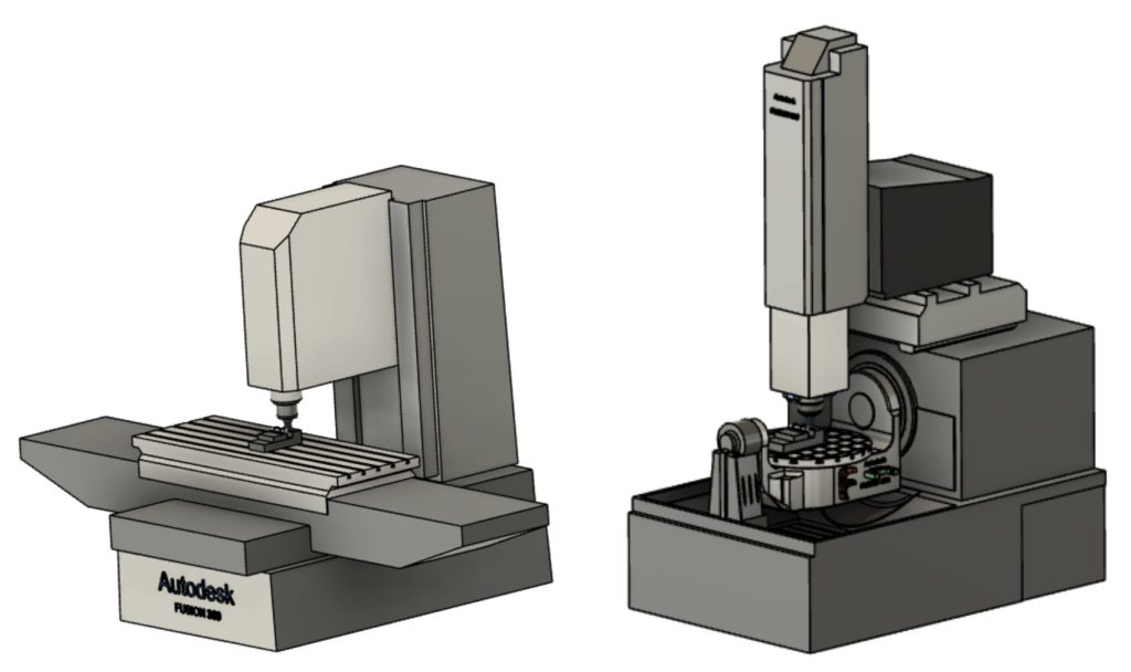
As shown above, we have now released machine simulation in preview! To allow you to get the most out of simulation, we have developed a machine building environment that lets you get your own machine model setup and ready for simulation. This allows you to define your machine kinematics, link them to the relevant model components and then finally jog the machine to ensure everything works correctly. Once complete, the machine is stored in your machine library for quick selection on future CAM setups.
- Learn more about Machine Builder.
- Learn more about splitting a toolpath using toolpath trimming.
- Learn more about changing tools without needing to recalculate a toolpath.
- Learn more about browser icons that indicate the status of an item.
New in Preview! Improved icons in browser items
Preferences > Preview Features > Browser Icons to Indicate an Item’s Status

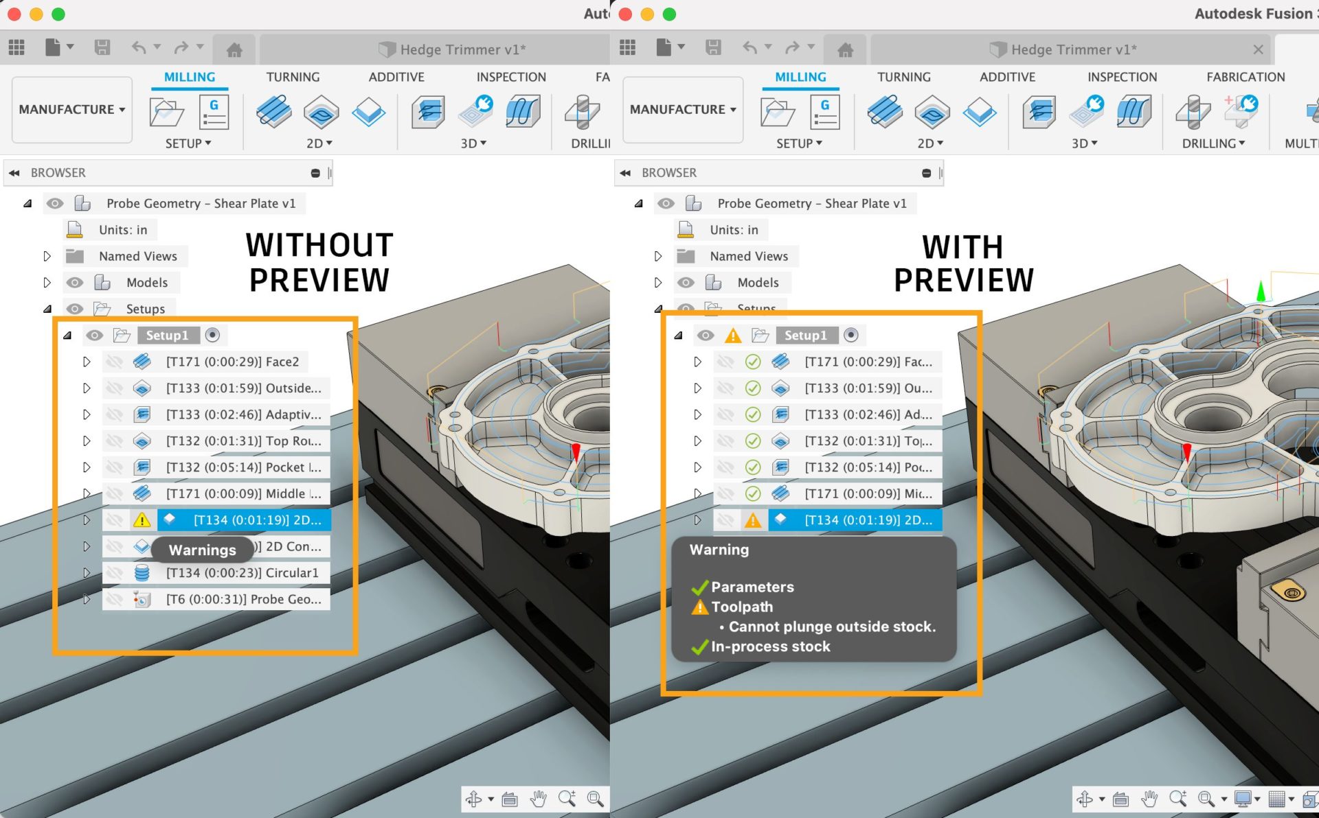
As part of our ongoing effort to improve usability of Fusion 360, we encourage you to check out this new preview feature around toolpath status. With the preview turned on, you’ll see new icons next to your toolpaths in the browser, giving you a better sense of whether they are ready to go or require your attention.
Improved! NC Program: switch to the new layout
The NC program layout has been updated to use the new post and machine library for selection and management of post processors. This makes it much easier to manage, select and use post processors from your local or cloud storage.
Extensions
New! Manage Extension now available
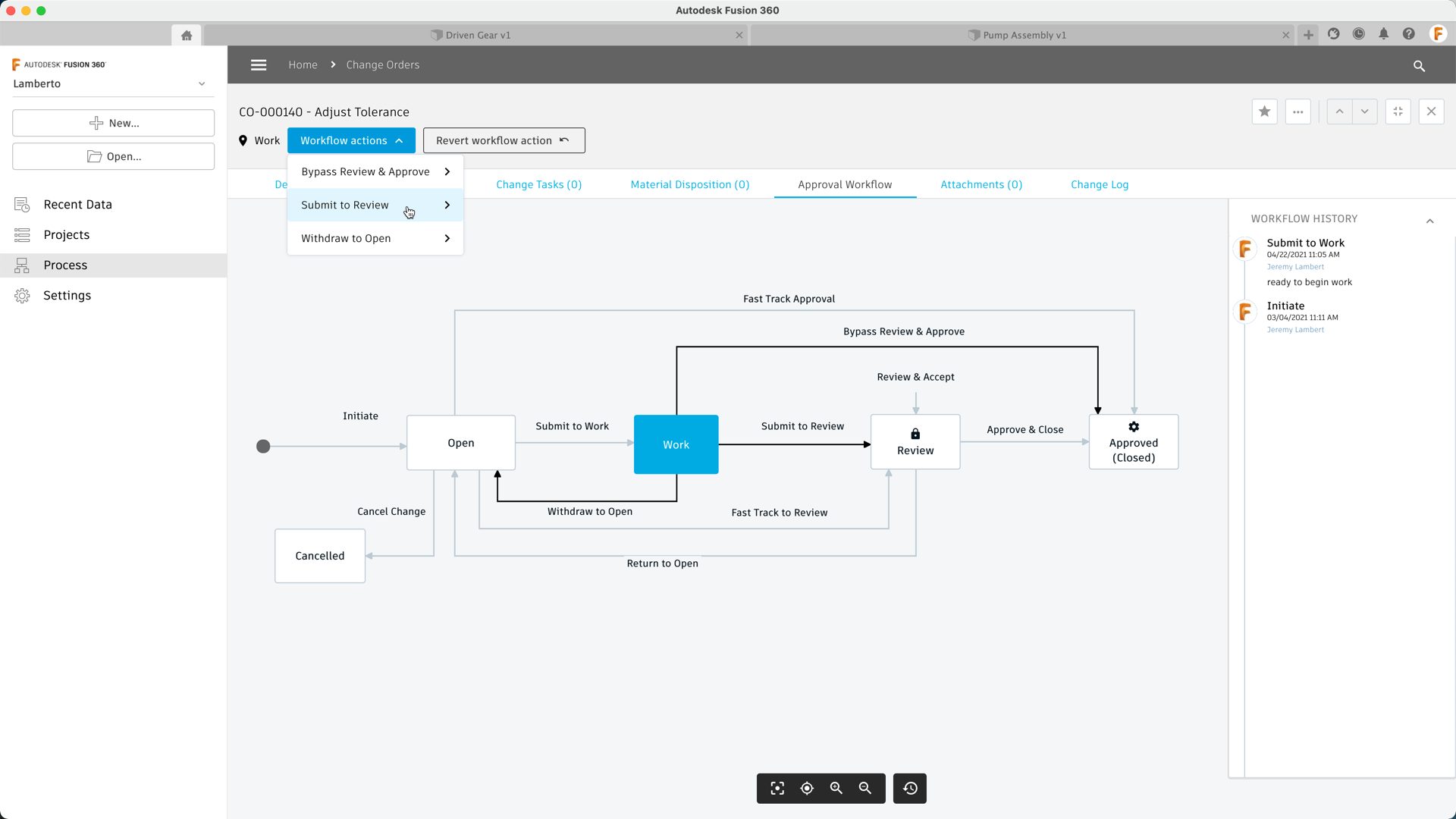
“We’re excited to announce the new Fusion 360 Manage Extension, which introduces advanced data management capabilities to Fusion 360. With this new extension, users now have additional tools to release design and drawing revisions, automate numbering and explore a change control process.
Change is inevitable with product development, and it can introduce a lot of confusion if it is not handled properly. A simple mistake like transposing two numbers within a part or drawing number can lead to scheduling delays, scrap, or rework. Similarly, when there are dozens of versions of a design or drawing, understanding which version is the final one that should be made or bought by customers can be confusing. There simply isn’t enough information to give consumers confidence that they’re grabbing the right version. Now, with the Fusion 360 Manage Extension, you can overcome these challenges. ” – Jeremy Lambert, Fusion 360 Product Manager.
To learn more about this extension, as well as how to access it, check out Jeremy’s recent blog post. You can also contact your local reseller and talk to a local expert to help you out.
See blog post
Talk to your local reseller
Notices, Fixes & Known Issues
To see details around this, our extended list of fixes, as well as known issues, check out this forum thread in our support forum.See Notices, Fixes & Known Issues.
Community
With so many of you creating awesome content and sharing your knowledge to the world, we’d like to highlight some recent videos you’ve created:
- What’s new in May 2021 product update | World of Fusion 360
- Create a Custom Machine Configuration in Fusion 360 for Hobbyist CNC | Shapeoko, X-Carve, LongMill | Product Design Online
- Fusion 360 Thin Wall Tool (New Thin Extrude) |Tyler Beck of Tech & Espresso
- Autodesk Fusion 360 – Static Stress – Validation Model | Mike Fiedler
- Converting a Sheet Metal Body into a Component in Autodesk Fusion 360 | John Hackney