See the latest fixes in V.2.0.13168
See the latest fixes in V.2.0.13162
This is one of the biggest updates we’ve released in a long time. Buckle up; there’s something here for everyone.
Usability
5 New Additive materials in the Fusion 360 Material Library
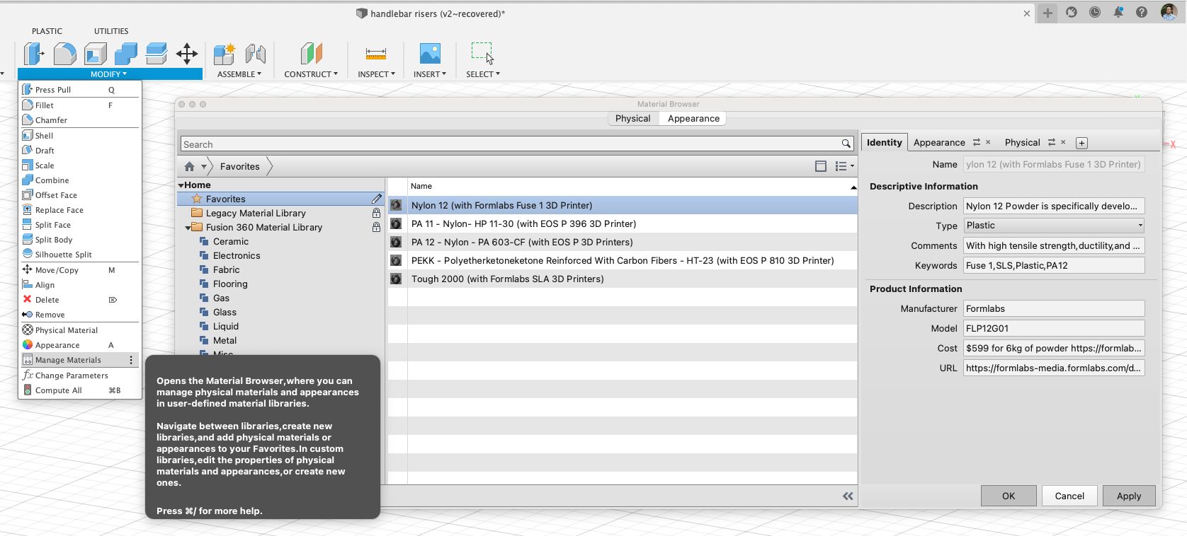
Through our partnership with EOS and Formlabs, we’ve been working with them and researching what are some of the most used materials for 3D printing. We 3D printed several sample parts and tested their performance in our material testing labs in Australia. Based on this research, we’ve introduced 5 new additive materials to the Fusion 360 Material Library. These materials are now available in the Design, Simulation, and General Design workspace. You can now assign these materials to your design so that you are accurately representing what your parts are made of, as well as the properties that come with these materials:
PA11 – Nylon HP 11-30 (with EOS P 396 3D printer)
PA12 – Nylon PA 603-CF (with EOS P 3D printer)
PEKK – Polyetherketoneketone Reinforced With Carbon Fibers – HT-23 (with EOS P 810 3D printer)
Nylon 12 (with Formlabs Fuse 1 3D printer)
Tough 2000 (with Formlabs SLA 3D printer)
Design
New Mesh face group Display Toggle command
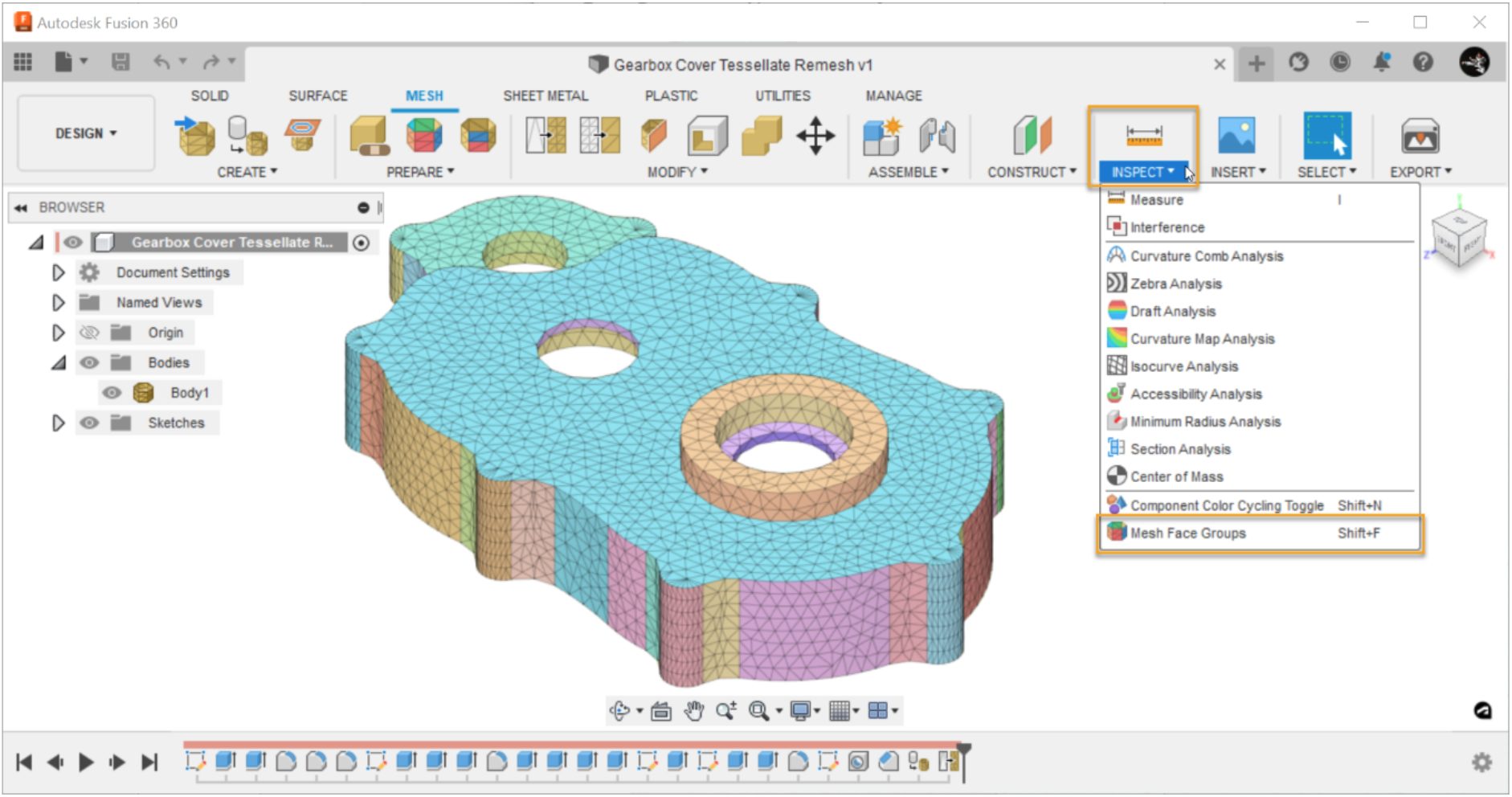
In the Design workspace > Mesh tab > Inspect panel, there is a new Mesh Face Groups display toggle. Access it there or press Shift+F to easily change the view style of Mesh bodies. It is important to see which triangles make up each face group. That is why we color each face group in a unique way. Creating Mesh face groups plays a critical role in mesh editing workflows and converting mesh bodies to Solid bodies. You can now also use them in the Manufacturing workspace while creating support structures for additive workflows. You may want to turn that colored display on or off depending on what you are focusing on. This new toggle and the keyboard shortcut will get you to the state you want much faster.
Learn how to show or hide face groups on mesh bodies
Ribs is now available in Boss Command (Product Design Extension)
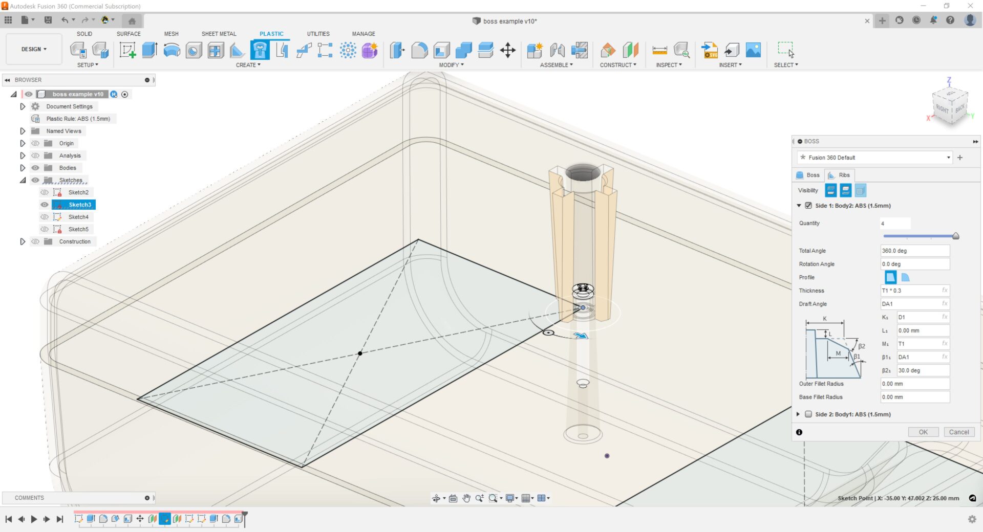
We added Rib options in the Boss command. This includes a preview of what the rib will look like, default presets, improvements to the Boss for screw connection, rib draft angle and fillet option.
Snap-fit improvements (Product Design Extension)
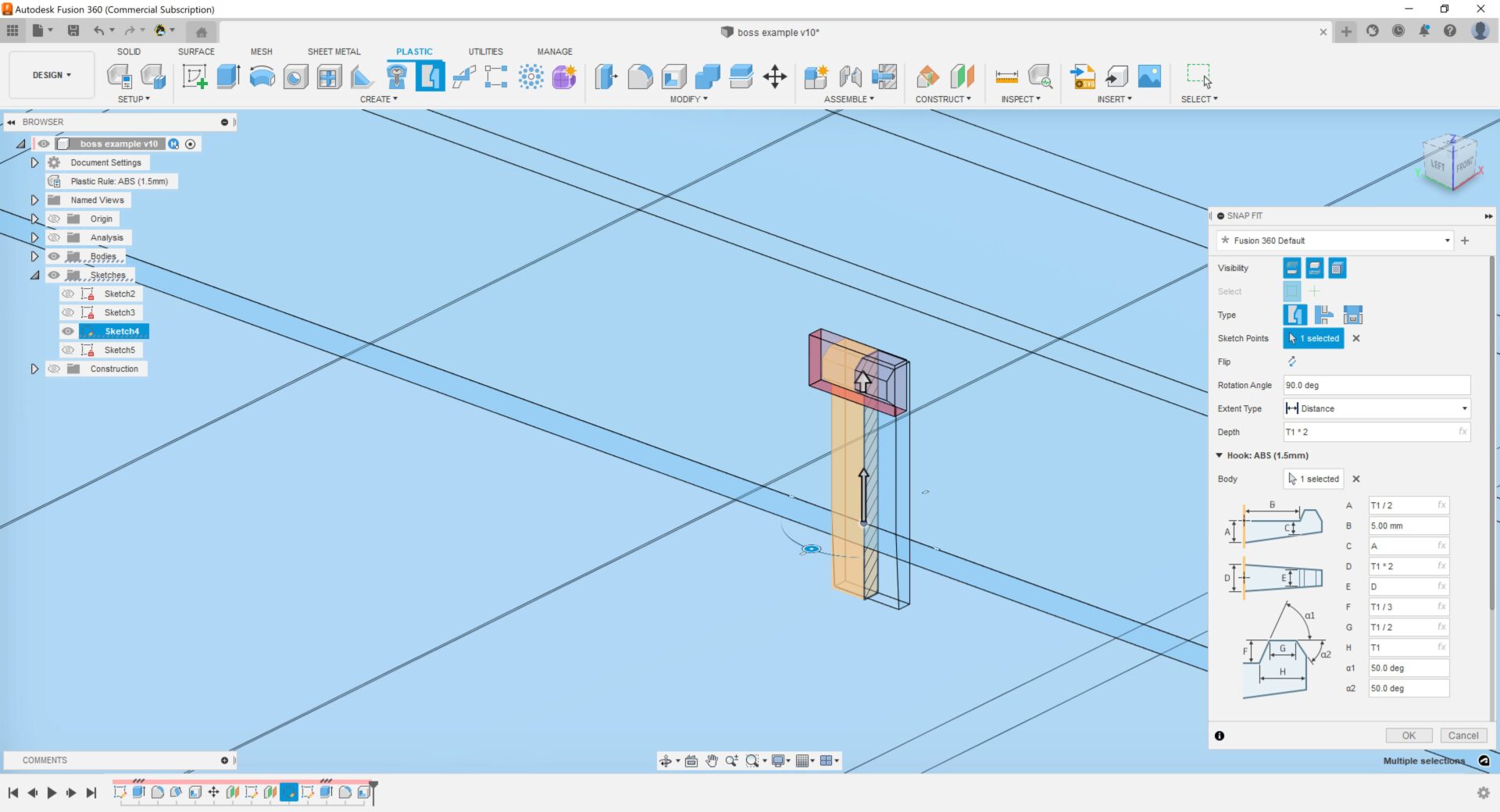
Snap fit now has better preview with transparency with section view, new selectors to select/deselect bodies, as well as having a Radius Hook Root.
Learn how to create a snap fit
Replace Component now supports patterned components
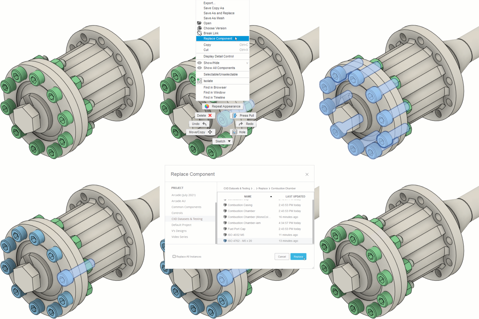
The Replace Component command that we introduced in January now supports replacing external components that are part of a pattern in Parametric Modeling mode. Select any instance of the component, right-click, then select Replace Component. Navigate to and select the new external component you want to use, and all the instances in the pattern update at once.
Learn how to replace external components in an assembly
Electronics
New Layer Stack Manager
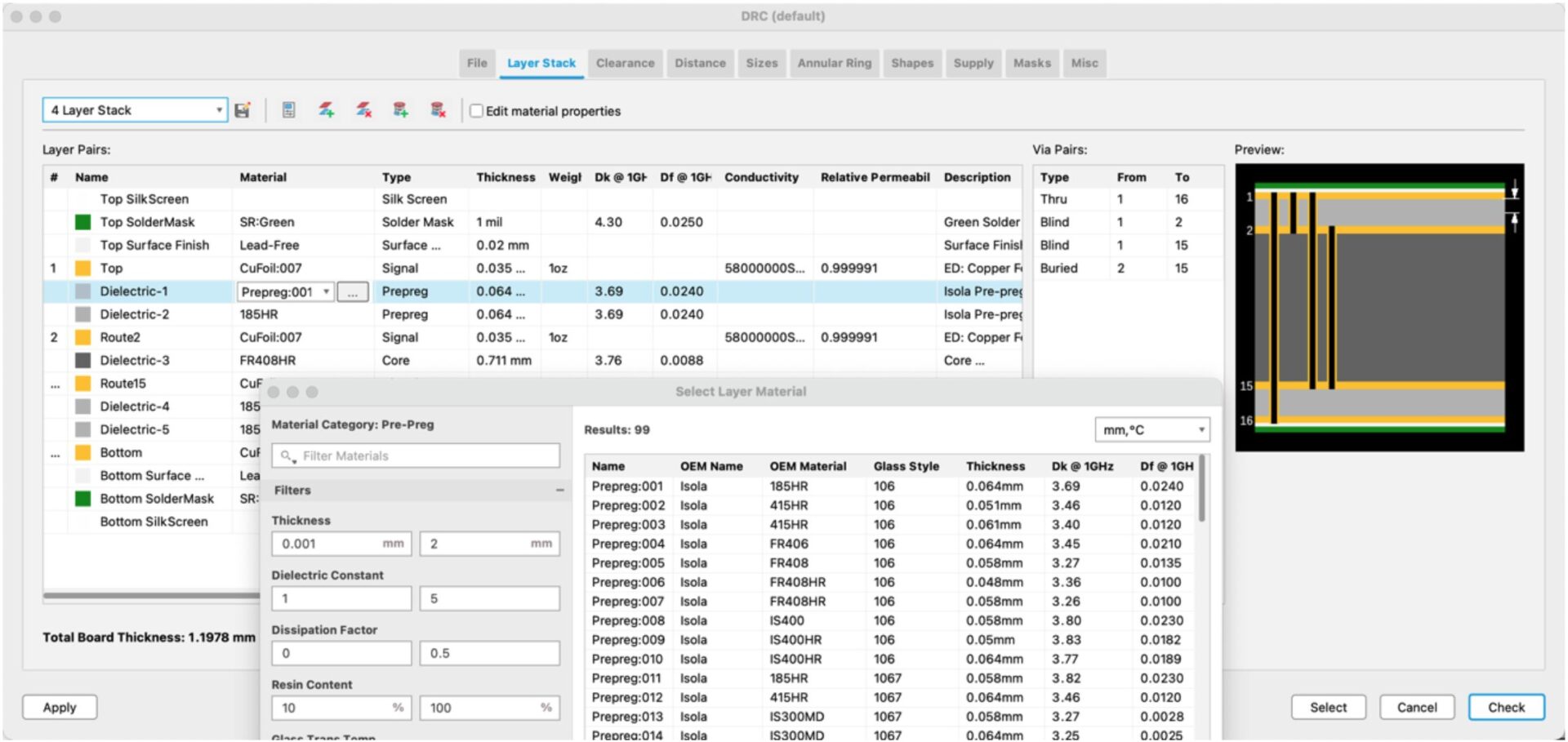
To ensure PCB manufacturability, certain design rules and regulations (such as clearance between traces, trace width and annular rings) need to be considered during the PCB design process. Before beginning the trace design process, the first step is to determine how many signal layers your board will need – i.e. your layer stack. The most common layer stack consists of 2 or 4 layers, but Fusion 360 can handle up to 16 signal layers.
Now you can specify the material (and material properties) used for all your PCB layers such as surface finish, the conductive weight property for your signal layers, and the type of dielectric material (prepreg or core) used to separate each layer. PCBs that require high speed communication, such as DDR, will use very different layer stack properties than a high-voltage power supply design. With this implementation, you’ll be able to capture and communicate your design intent to a manufacturer more accurately.
Learn more about the new Layer Stack Manager
Support for Slotted Pads
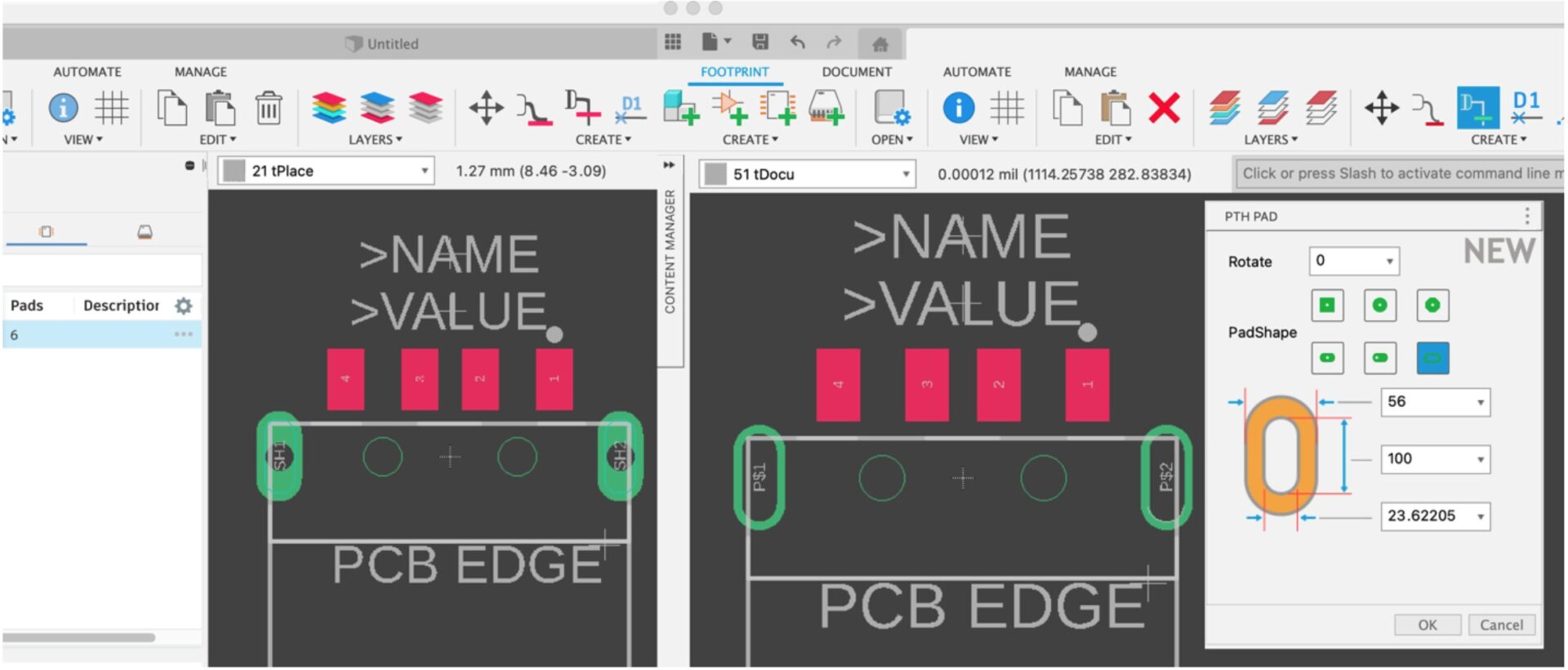
It is finally here! Many of you have contacted us asking for support for slotted pads, and we delivered. Slotted pads are commonly used for components that are subject to physical interaction such as USB-C connectors, where additional bond strength is required to resist the stresses imposed upon the board. Historically, users have been forced to use workarounds that consisted of using a long pad with a manually drawn slot in the milling layer; this is all in the past. With support for slots, you are now able to have that USB connector with slots generated quickly and natively.
Improved Handling of Panels
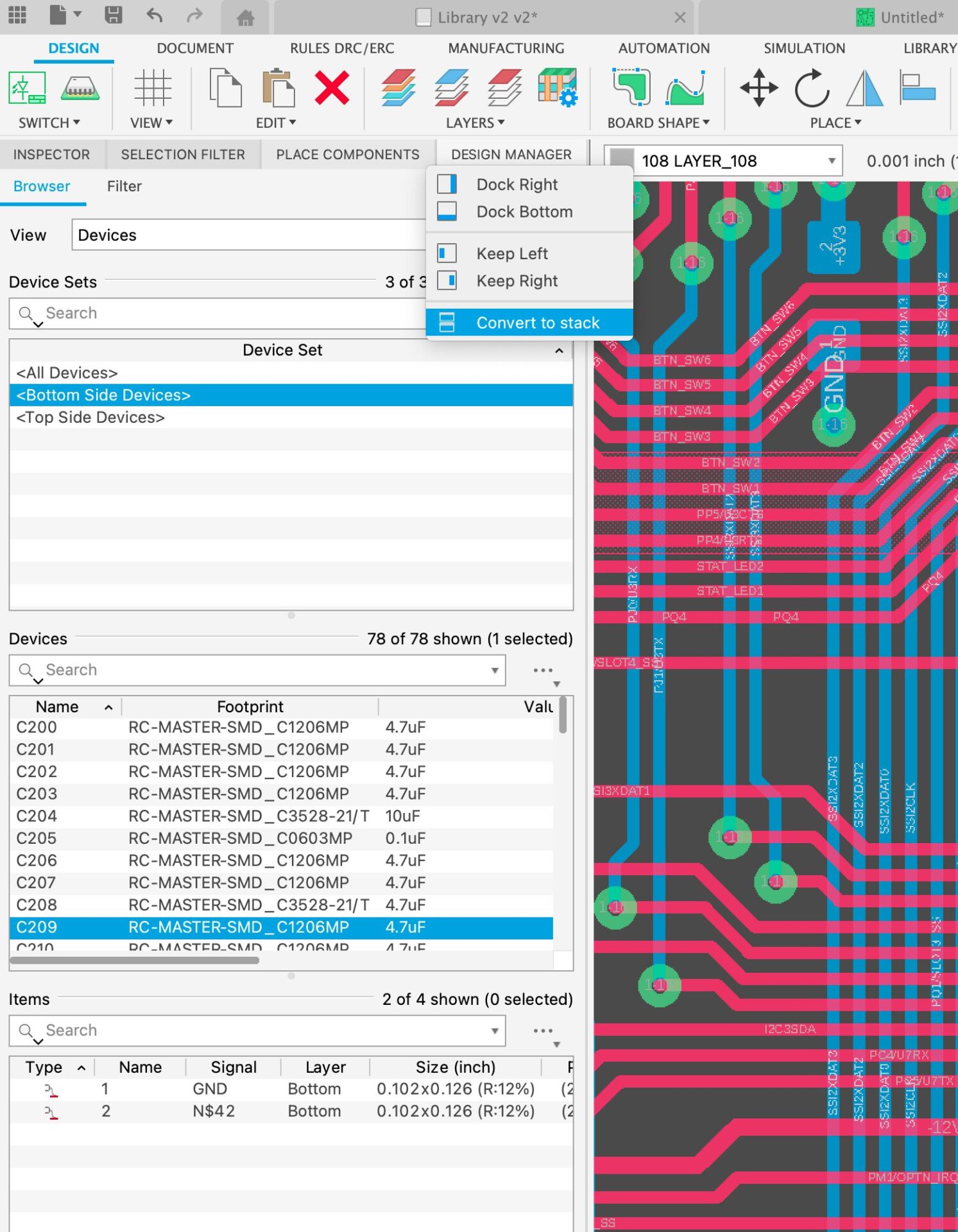
The Fusion 360 electronic workspace is surrounded by helpful panels that make it easier to navigate your design. The downside is that this convenience can make the Fusion 360 electronics workspace area crowded, especially when working on laptops or desktops with smaller monitors.
You have asked for a better panel docking experience, and our team of developers once again has delivered. With the new panels and docking system, it is now easier than ever to relocate, place and configure panels. Per your preference, panels can now natively be floating or docked, tabbed, stacked, collapsed or expanded. Don’t worry, your layout preferences are saved per environment/workspace and held across sessions allowing you to be even more productive!
Learn more about working with information panels
New Radial Template added to Library Editor
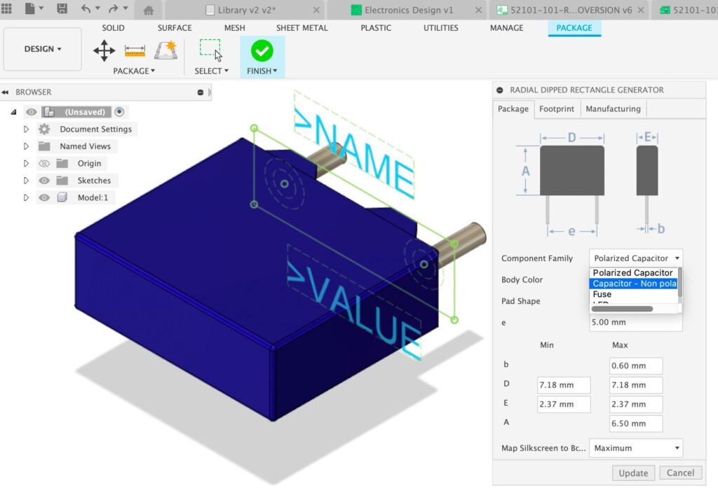
Fusion 360 includes numerous libraries created by our team of librarians as well as components added by partners such as TE Connectivity, Wurth electronics, and many others. If by chance you determine that what you’re looking for is not available, making your component from scratch with Fusion 360 Electronics couldn’t be any easier. The library editor includes an easy-to-use package generator that utilizes templates to streamline the component creation process using mechanical specifications.
In moments, you will have the footprint and 3D model created. We are excited to let you know we’ve added a new template for Radial Dipped Rectangle parts. This package style is different from the Axial component since the leads come out of one end vertical to the board. This component is somewhat different because its construction uses a plastic dielectric material made from a polymer. Radial dipped capacitors are highly coveted due to their low distortion factor and frequency characteristics, this makes them great for high voltage environments and high-frequency applications such as coupling/decoupling circuits, audio circuits, and many more.
New Sync library index
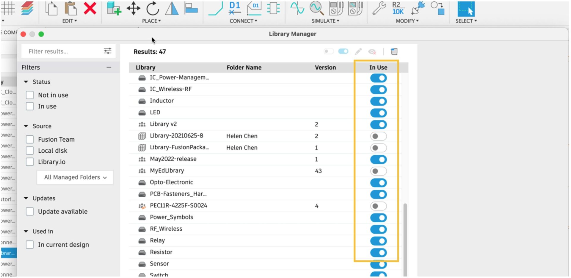
During the last few years, the physical location in which we do our work each day has drastically changed for many of us. This could be working from home, the office, or on the road, including the use of multiple computers. By switching computers, it is relatively common that you might lose many of your design environment preferences.
To help address this impact to productivity, we’re enabling your library preferences to travel with you. Preferences automatically load when you log into your Fusion 360 account from any computer. You will no longer have to navigate the repository of libraries to activate the ones you need to continue working. This feature makes Fusion 360 Electronics portable and streamlines your design time by automatically loading your library status preferences.
New Add-in Ultra Librarian
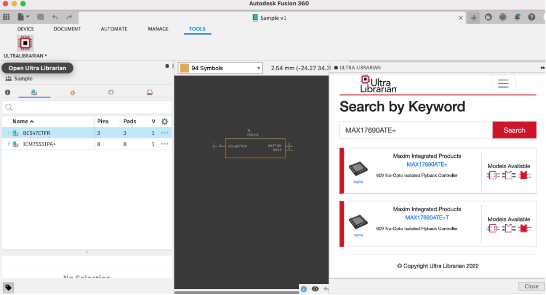
The Autodesk Fusion 360 App Store is a marketplace that allows partners and 3rd party developers to extend the capabilities of Fusion 360 by providing Add-Ins and Plugins. We are announcing that Ultra Librarian has developed an Add-In for Fusion 360 which provides access to their rich repository of design ready electronic components. Ultra-Librarian has a significant amount of electronic CAD components with schematic symbols, footprints along with 3D Models. In addition, the component description also includes links to the data sheets and the product page. With this new Add-In, you can directly import the parts required for your design into your library that can be accessed from Fusion 360 Library, Schematic & PCB workspaces. You can quickly find the verified parts in their ever-expanding database of parts.
Learn more about downloading Ultra Librarian
New User experience improvements: Updated Icons

Our user experience team has delivered a comprehensive update to all of the electronics toolsets with the ambition of making commands more visually representative and distinct, improving productivity and learnability.
New Preference Option: load 3D model when loading electronic document

Fusion 360 electronics is a design environment directly tied to the 3D PCB. The 3D PCB is not only a realistic preview of what your design will look like, but further unlocks advanced capabilities such as e-cooling simulation and bi-directional ECAD/MCAD collaboration. The 2D and 3D PCB are associative, meaning all members of your multi-disciplinary team have live access to the same Fusion File, showing any collisions or interference between components or enclosures in real time – reducing the chance of potentially costly rework.
For your convenience, loading your electronic design would automatically load the Schematic, 2D PCB, and 3D PCB all at once to maintain synchronization. With larger 3D PCBs, this may take some time. With this update, when opening the electronics design file, you can now choose to disable opening the 3D PCB. Since you are still opening the Schematic and 2D PCB through the electronics design file, synchronization is maintained and you are able to get to work faster without waiting on the 3D PCB.
Learn about Fusion 360 Electronics
Generative Design
New outcome in setups (Experimental Generative Solvers and Features Preview)
As we continue to develop and mature our Experimental Generative Solvers and Features Preview, we are adding an additional outcome to the generation process based on new solver technology we are working on that will bring improved performance and improved scalability. You will now see an additional outcome in setups that contain fixed, pinned, or frictionless constraints and force, pressure, moment, and bearing load types.
Note: Setups that contain remote forces, remote moments, remote constraints or point masses will not generate an additional outcome at this time. Additionally, the die casting manufacturing method will not produce an additional outcome.
Drawings
New Auxiliary Views
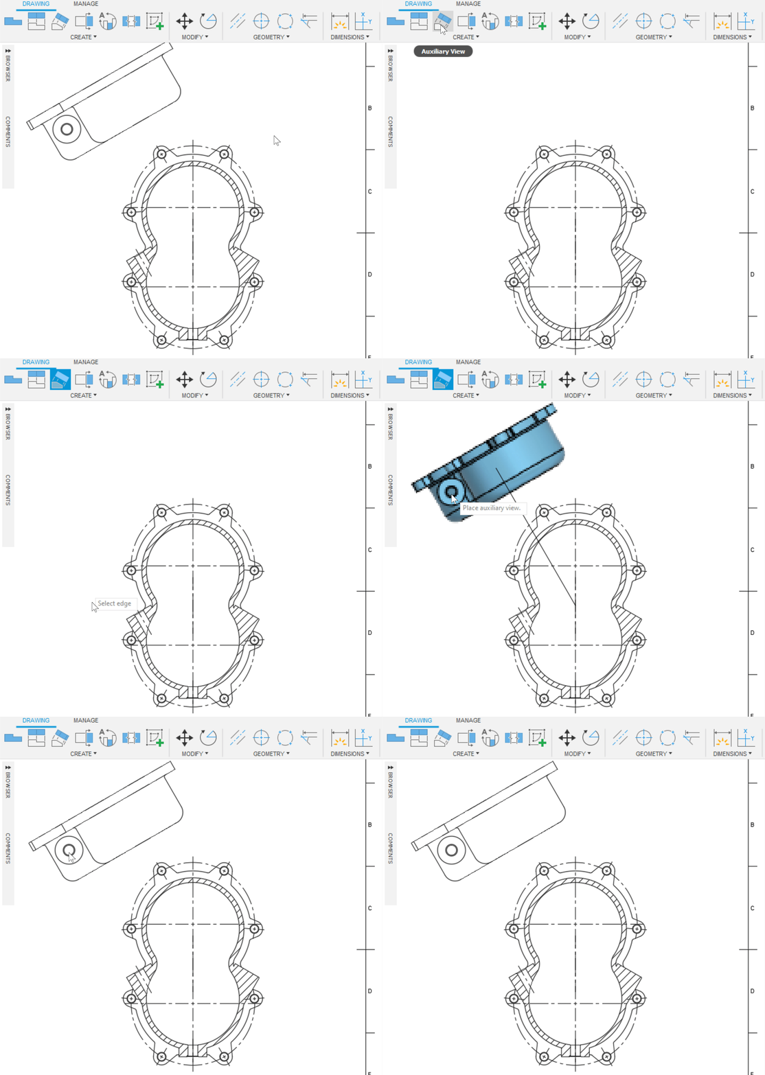
With the introduction of Auxiliary views, detailing of features on faces at an angle just got a lot easier. Auxiliary views let you project a view parallel or perpendicular to a face or edge.
New Arc Length Dimension
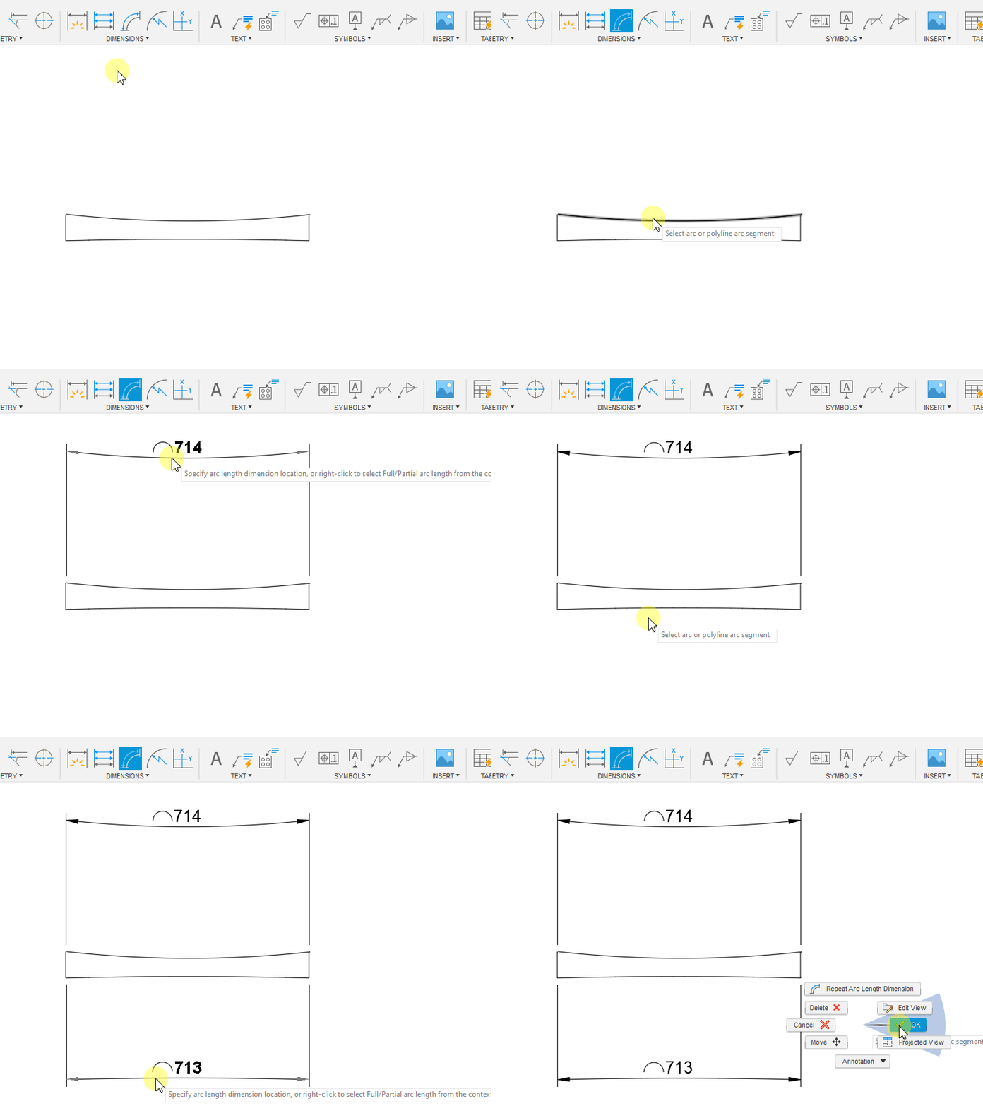
We’ve added a new Arc length dimension to our drawing toolset. This new tool lets you create dimensions that display the true length of arcs.
New Jogged Radius Dimension
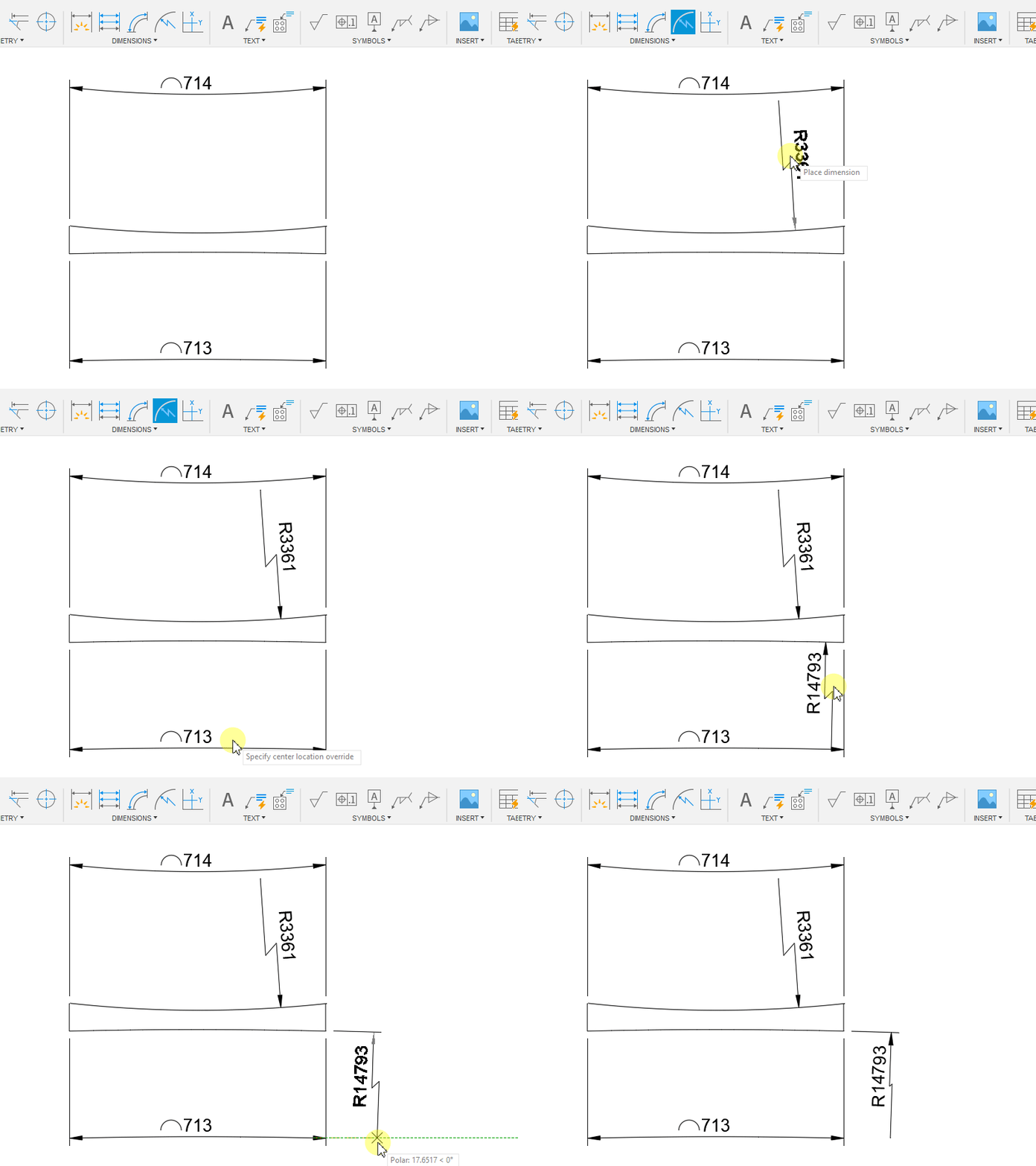
When placing radial dimensions on large arcs, or when space on a sheet is limited, The Jogged Radius Dimension, lets you override the center point of the arc and displays a jogged extension line.
New Model Properties in Title Blocks
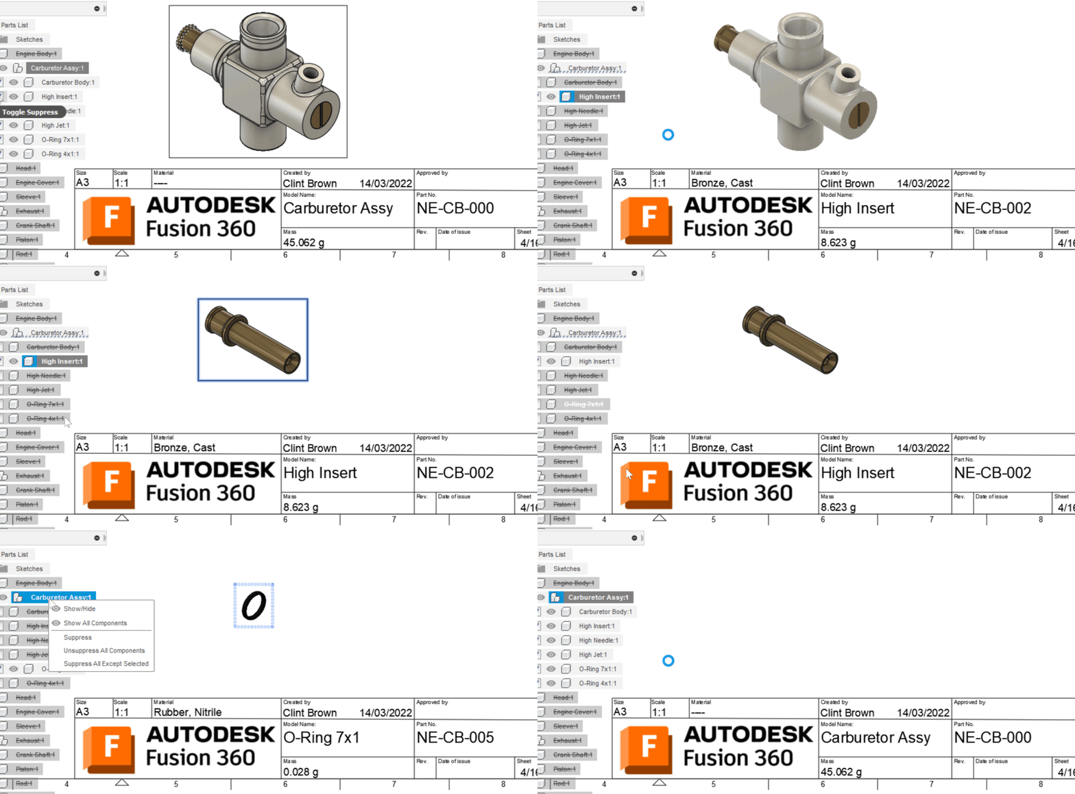
You can now insert Model (reference) properties such as Part Number, Part Name, Material, and Mass into your title blocks. What’s more, is that these properties are “model aware.” So, if your drawing displays an Assembly (or part of an assembly), the properties displayed will be for the assembly. If a change is made and the drawing only shows a single part, the properties will reflect just that part, and vice versa.

New Mass unit overrides in Title Blocks and Parts Lists
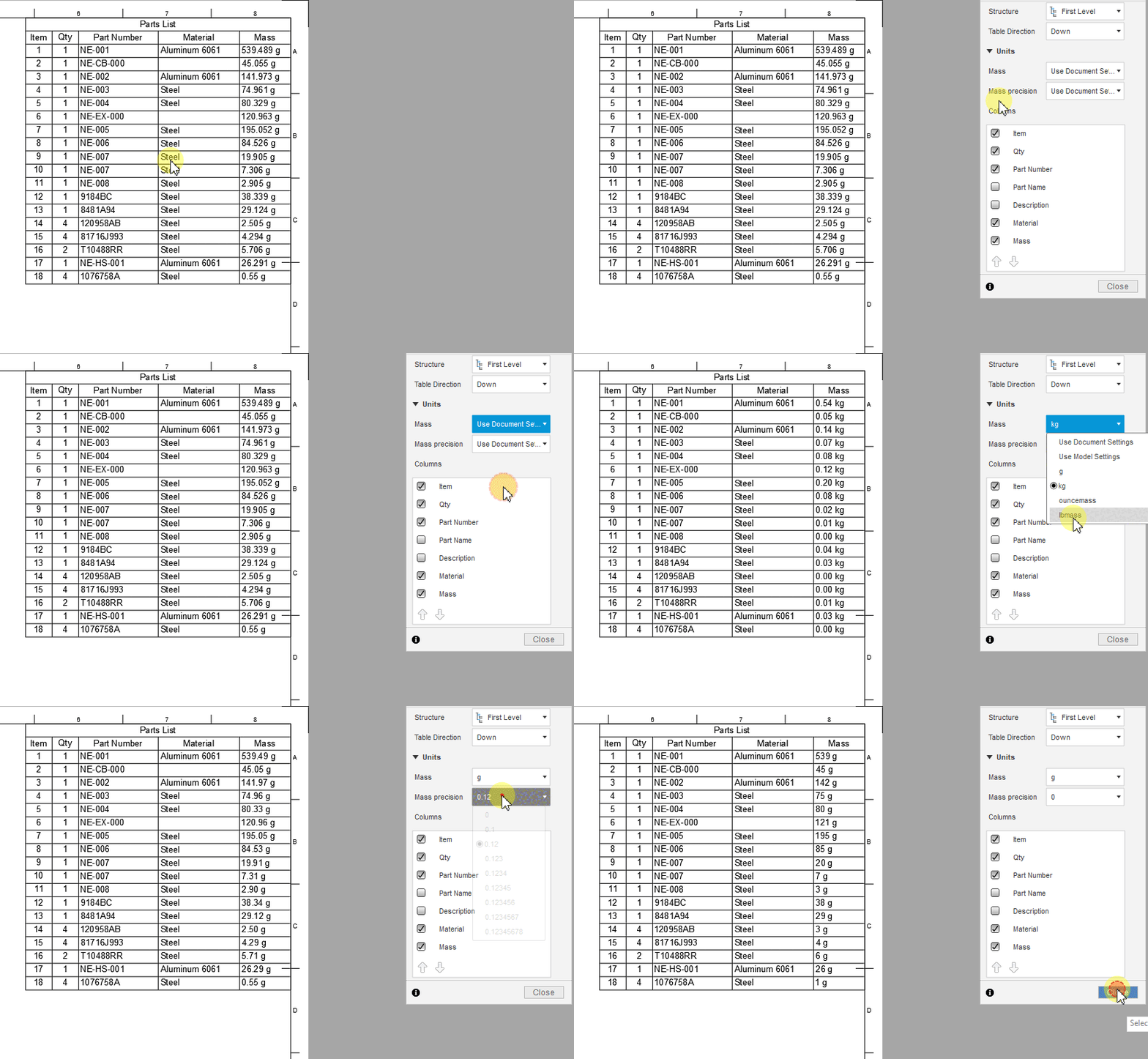
It’s now possible to override the Mass units on Parts Lists and Title Blocks. Double-clicking on either a parts list or a title block will bring up a new option which allows you to override the displayed Units. By default, units follow the Document Settings. It’s now easy to set precision or change the displayed units entirely.
Simulation
New Quasi-static analysis study type

Before this product update, a quasi-static simulation study was only possible if you selected an Event Simulation and changed the Movement option in the Manage >Settings dialog to Quasi-static (no inertia). This was really buried, and it should really be its own study type.
Now when you enter the Simulation workspace, you can select a new study type called Quasi-static analysis (left picture). In addition, note that Event Simulation has been renamed to Dynamic Event Simulation (right picture). Quasi-static analysis can be used to solve for large deformation & contact problems that involve large sliding motions and friction, or Nonlinear material behavior such as large plastic deformations.
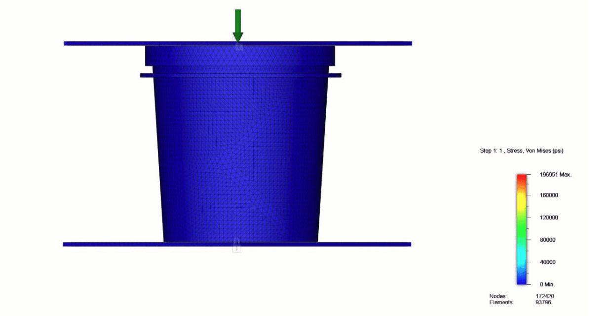
Learn how to set up a Quasi-static event simulation study.
New reaction data and result visualizations for Contact Force and Contact Pressures

We have added 2 new result visualizations for Contact Force and Contact Pressures (left picture). We have also added enhancement where the user can now get Reactions data for Force and Moment at Contact locations as well (right picture). These Reaction values can then be used as a reference when setting up a Generative Design Study.
Manufacture
Notice: Retiring the Legacy Tool Library
In the next release, we plan to fully retire the legacy tool library, moving the Tool Library out from behind public feature flag and making it the default experience for all Fusion 360 manufacturing users. We appreciate the patience and feedback from the community in the time since the release of the new tool library behind feature flag, and we feel with the extremely low usage of the old library, pace of improvements, ability to quickly address bugs and other issues, and the cost of managing both libraries, now is the time to fully transition from legacy to new. If you have any concerns and especially if you feel you must use the old library for any reason, please let us know at fusion.tool.library@autodesk.com
New Accessibility Analysis
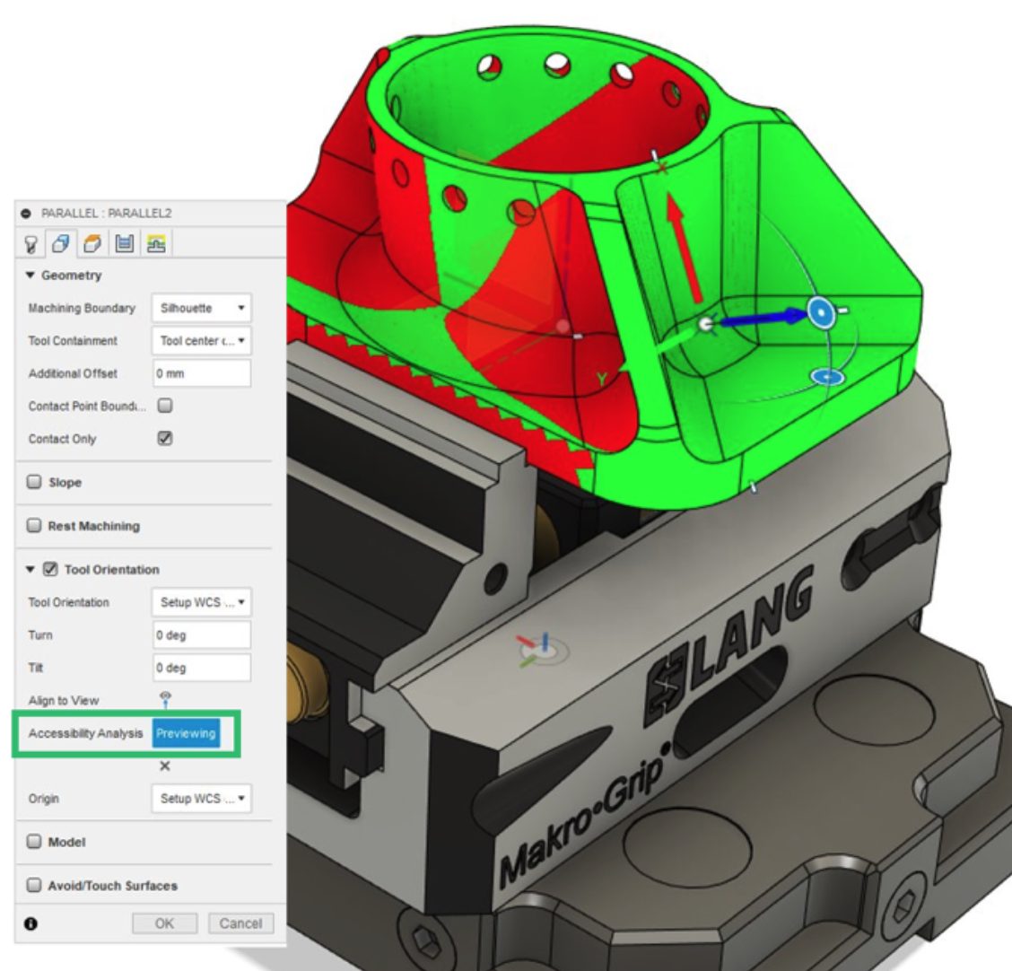
Now when you are working on tool-path strategy, there is a new option under the Geometry tab > Tool orientation called Accessibility Analysis. This shading option gives you a preview what areas of the part are less accessible by the cutting tool. It is aligned with selected tool orientation. It will update as the tool orientation changes.
Learn more about Accessibility Analysis.
Import & Export CSV files
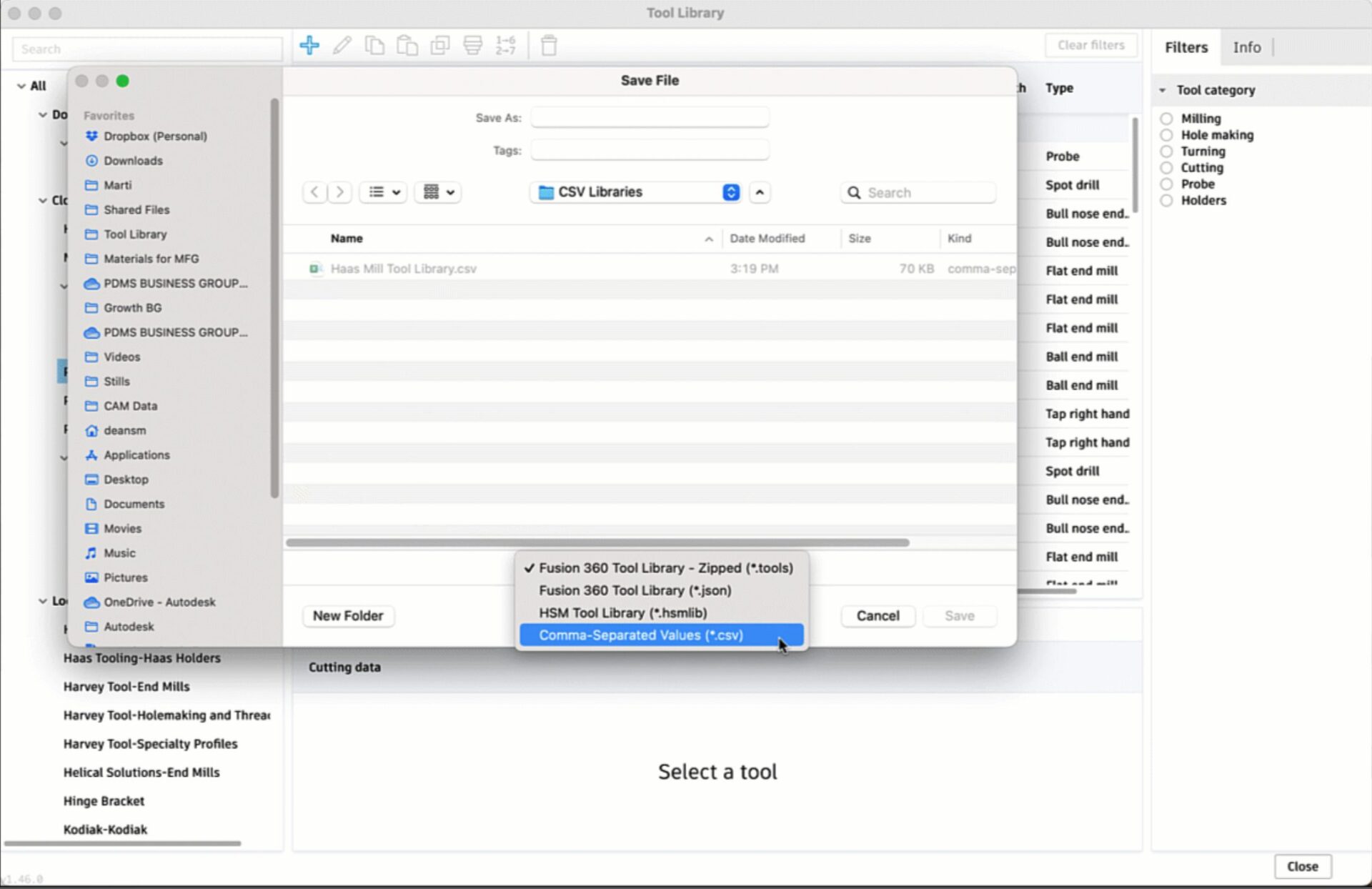
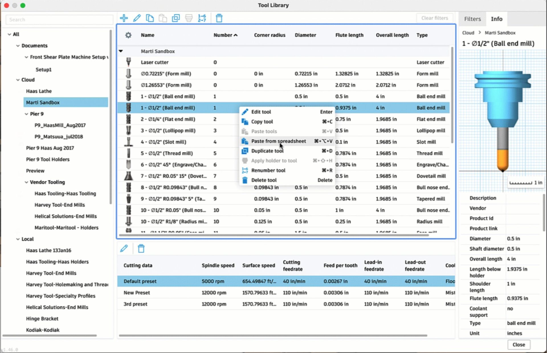
You now have the ability to import and export tools from the tool library through management in spreadsheet apps (for example Excel, Google Sheets). Management activities might include bulk editing, bulk creation of cutting presets, and other automation workflows. Also, we added the ability to copy and paste selected tools between the tool library and the spreadsheet which gives the user more granular control over their libraries.
More options to set defaults for tool strategies in Manufacture Workspace
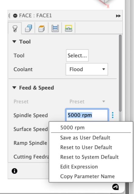
Now when you hover over a field in your tool strategy dialog, you’ll see a 3-dot menu appear below your cursor. Clicking it will reveal options for you to save the value/setting as a default, reset, edit, as well as copy it as a parameter name. This brings some consistency between what you can do in the Manufacture workspace and the Design workspace.
New & Improved Post Processors
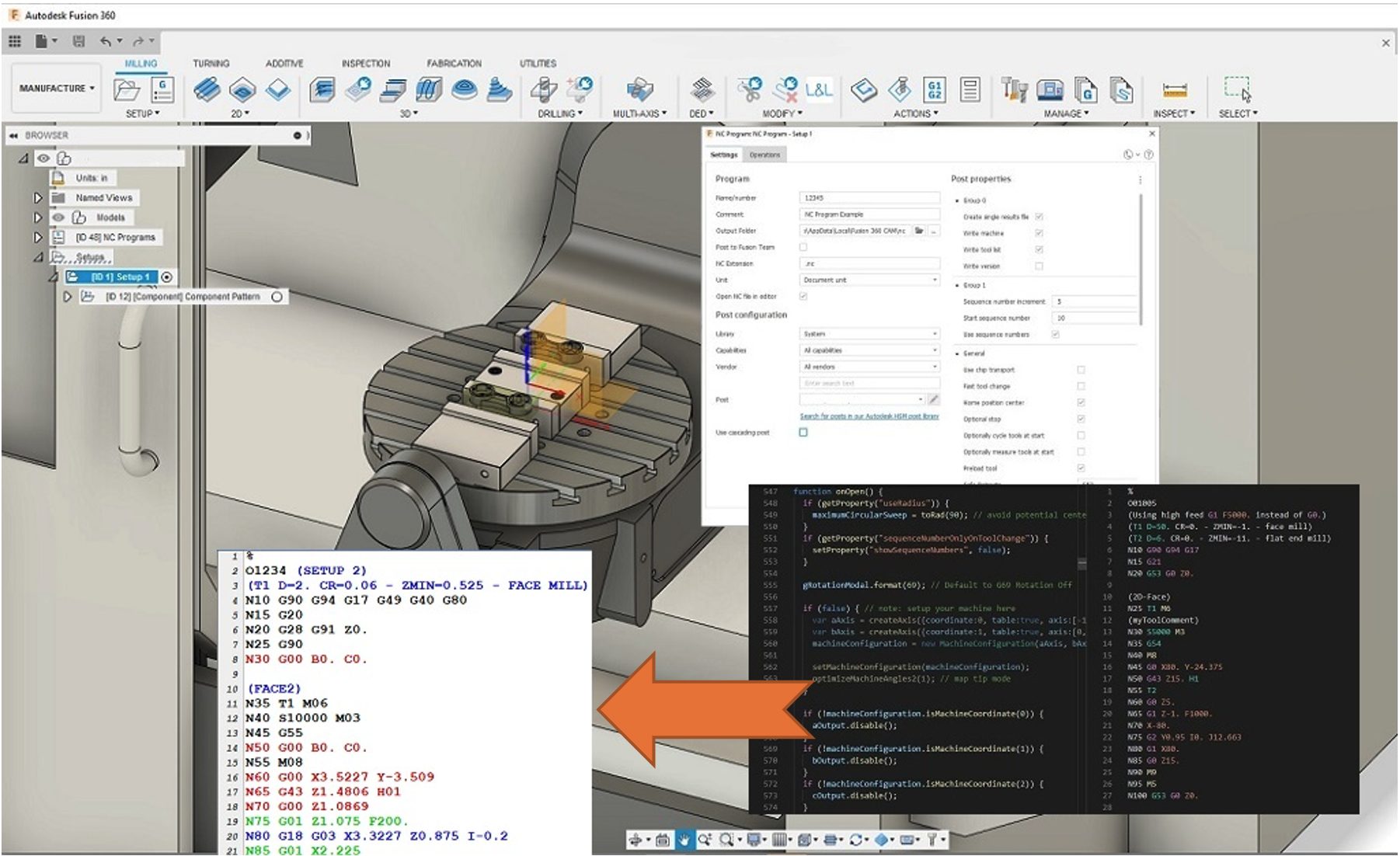
If you haven’t seen our recent forum post, we just dropped a bunch of improvements to existing post processors, as well as new ones for Datron M8Cube 3ax, ax, and 5ax machines. Head over to the forum thread to check out all the latest in more detail.
New Manufacture Previews
We’ve dropped 3 new Manufacture previews for you to try in the Preview Features section of your Preferences:

Building a tool with relevant expressions is a popular way for you to build out presets that are linked to tool geometry and will therefore consume any changes automatically i.e. Tool step-over can be linked to the tools diameter by entering a step over value of tool_diameter*.1 this results in a value being returned of 10% of the diameter value for the step-over.
To help you with this, we have added an auto complete parameter mechanism which will only return relevant parameters to help you create expressions. Through this work, we have also ensured that any modification to the tool geometry that will alter the cutting presets will modify them all and not just the preset that is focused.

If you decide that a warning for an operation does not require further attention, you can choose to hide the warning from the Browser, to allow you to focus on other warnings or errors. The warning remains hidden until the operation is regenerated. Errors always remain visible.
Learn more about hiding warnings.

This new Machining Extension preview enables you to try new multi-axis options for 3D strategies. You’ll be able to Reduce number of setup’s, avoid costly fixturing, use shorter tools, achieve better surface finish, have less tool deflection, and setup more optimized feed-rates.
Learn more about multi-axis options for 3D strategies.
Additive
Additive Simulation is now a part of the Additive Build Extension
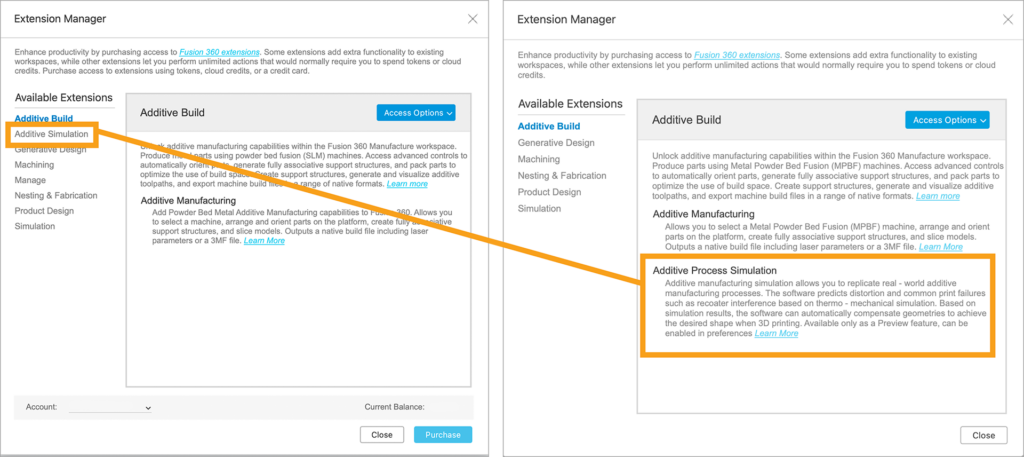
Previously, Additive Simulation, which is a technology preview functionality, was available within the Extension Manager as a standalone option. Yet it also required users to gain access to the Additive Build extension prior to being able to simulate the metal additive process.
In this product update we are merging the Additive Simulation capabilities into the Additive Build extension. You no longer need to gain access to two separate extensions to fully benefit from Fusion 360’s metal additive capabilities. Simply access the Additive Build extension and you can setup your metal additive builds like before. If you wish to use Additive Simulation capabilities and give us feedback, you can turn it on from the Preferences > Preview Features section just like any other tech preview. We think this slight change will streamline the access to Additive simulation technology and keep things organized.
Learn more about process simulation
New Center of Gravity Height Ranking criterion for Automatic Orientation
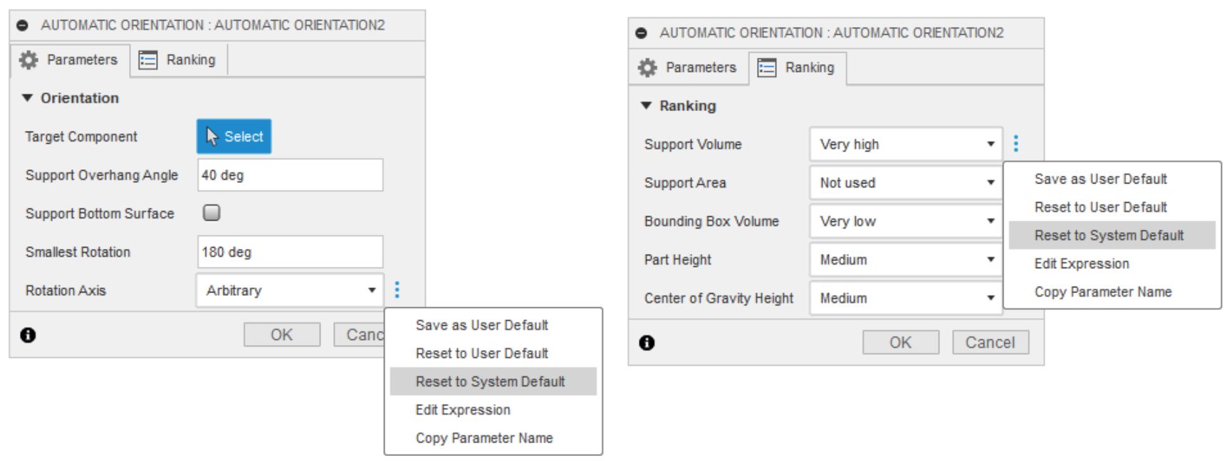
One of the first things you work on when creating an Additive setup in Fusion 360 is positioning your parts within the build volume of your printer. This often involves using the Automatic Orientation function available within the Additive tab: Position panel. In this product update, we are including a new Ranking criterion, “Center of Gravity Height”. When used alone, this criterion will rank the outcomes of an automatic orientation study, with lowest center of gravity, above other orientations.
We also modified the System defaults for the Automatic orientation dialog, so that the top ranked orientation outcomes you get after running an orientation study is the desired outcome for printing parts with an FFF printer. This change to the system defaults eliminated the need for a duplicate template to exist in the template library so we removed the “Automatic Orientation -FFF” template from the installer.
New Additive Support Templates in Template Library
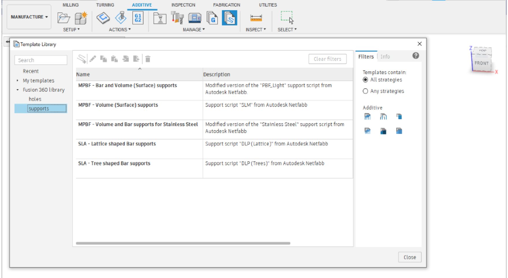
Once you have oriented your model, it’s time to see if they need support structures to 3D print them. If your model is in an orientation such that you have large overhanging regions below a certain critical angle, you will need to support them. There are different geometries you would use to support a model depending on whether you will print them using a MPBF (metal powder bed fusion) printer or an SLA (Stereolithography) printer. With all the support operations we have available in Fusion 360, it may be difficult to know which one to use and what specific setting you should use in each support action.
To make getting started with Additive Supports a bit easier, in this update we are including Several templates you can choose from when creating Additive supports. If you wish to use one of these templates, create an Additive setup with your SLA or MPBF printer, access the template library, choose a support template, and add the operations in that template to your Additive setup. Close the template library and edit each support operation to choose a target object to support.
Learn how to use the Template Library
Select Mesh face groups while creating Supports
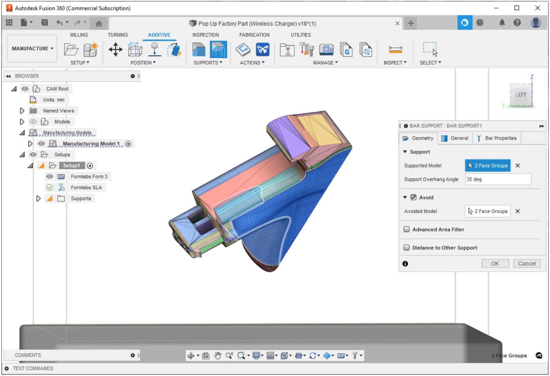
Speaking of selecting objects to create supports, this product update also extends the type of objects you can select when creating support structures. In addition to selecting bodies and faces, you can now select Mesh face groups to Support and/ or avoid while creating Support structures.
Taper angle for padded bar supports
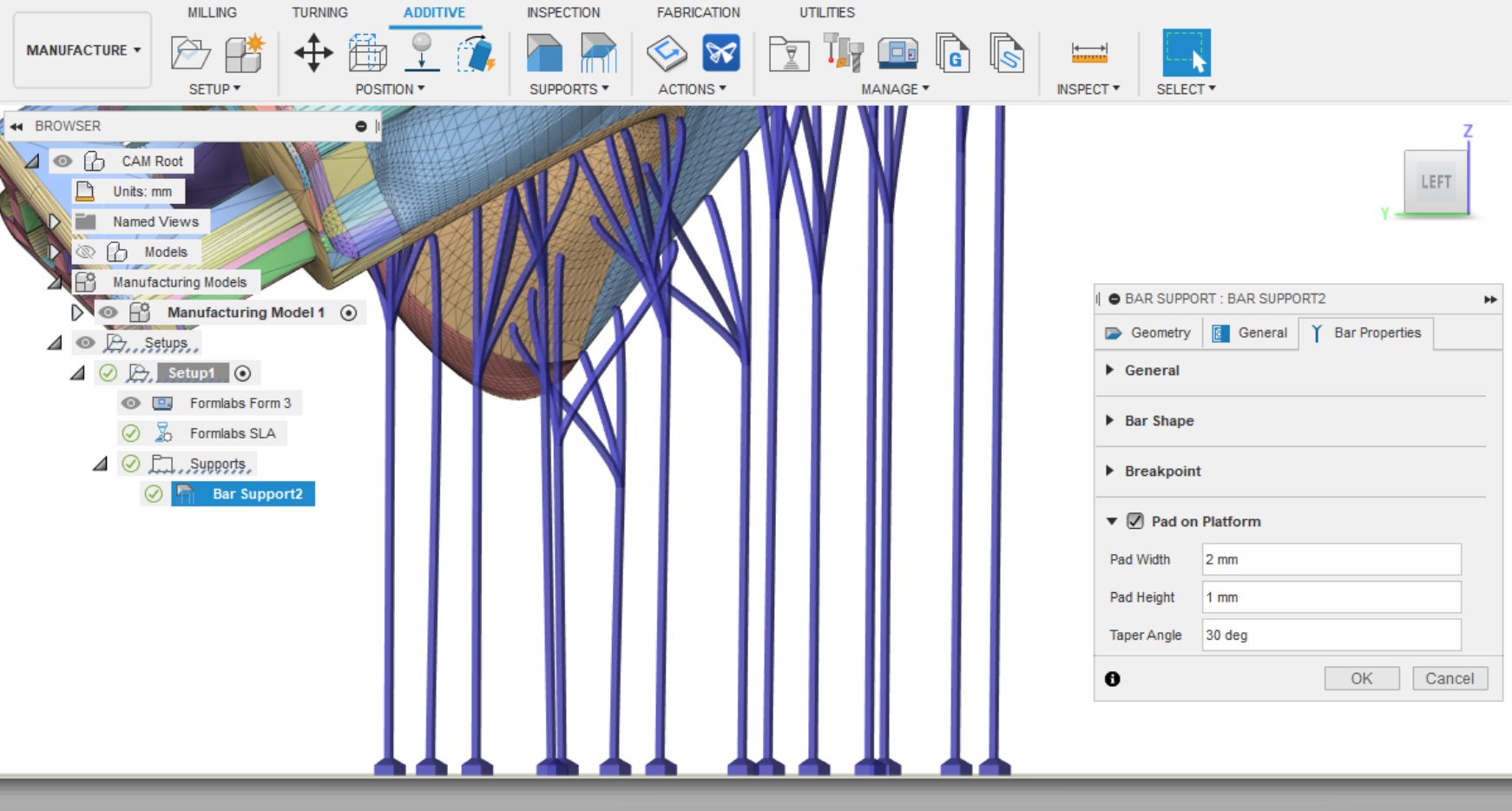
Now that you selected what to support, its time to talk about how to support it. In this product update the padded bar supports you create can have a taper angle associated with them. In the past the pads you add to bar supports were always perpendicular to each other. Now you can add a taper angle to that connection so that your supports are more stable during the printing and post processing processes.
New MPBF machines added
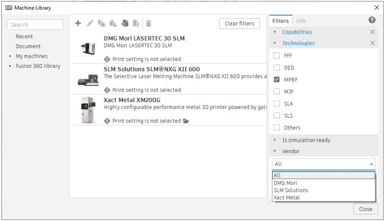
The Machine Library now includes several new MPBF machines from three key metal additive manufacturers. SLM Solutions: SLM NXG XII 600, Xact Metal: XM200G and DMG MORI: LASERTEC 30 SLM. These machines can be downloaded from Fusion’s online machine library, or you can access them directly within Fusion 360 if you have the following technology preview enabled.
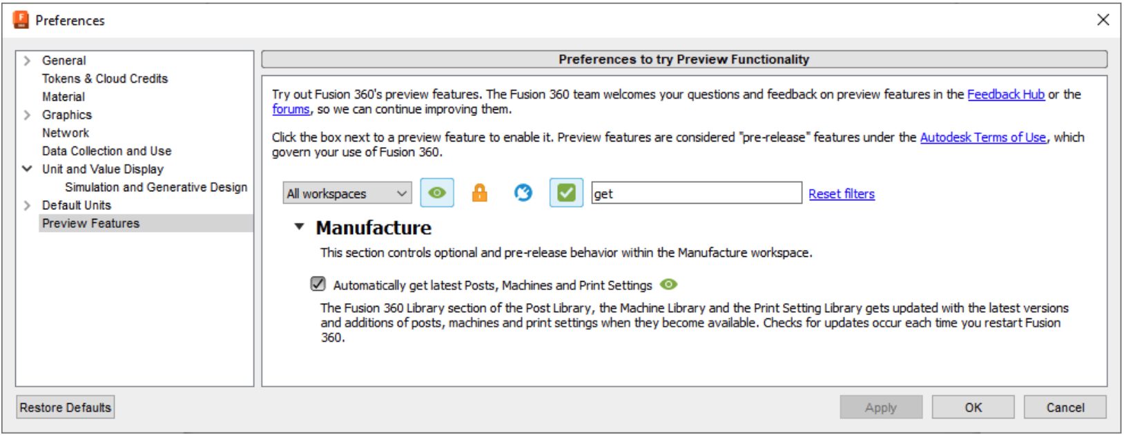
The online machine library now also hosts Print Settings. This will allow us to deliver new print settings to you more regularly and you will not have to wait for the next major update of Fusion 360 to have the latest machines, posts and print settings in order to 3D print with your hardware. As a part of that promise, we posted new print settings for a popular filament PETG so you can 3D print with your desktop FFF (fused filament fabrication) printers as well as several print settings for Renishaw MPBF printers. If you need a print setting for a certain printer and you can’t, find it on our library, please reach out to us and let’s work together to include it for everyone to benefit from it.
New Pause and Filament Change options for multi-color/single extruder printing
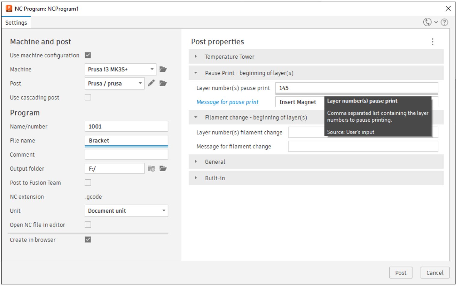
Using the latest Ultimaker post or, Prusa post, you can now Pause your prints to insert items such as magnets by simply typing in the layer number(s) you wish to interact with your print during manufacturing. You may also utilize the Filament change option to print with multiple colors on your single extruder Prusa printer. Just make sure you are using the same material when changing filament mid-print.
See more Support Structure Improvements for FFF, SLA ,and SLM Machine
Learn how to prepare parts for additive manufacture
API
Fusion Data API now in beta release
We are very excited to announce that a new cloud-based API has been released to a Beta preview. Previously you could access Fusion 360 file information via the Forge Data Management API and perform translation and viewing using the Forge Model Derivative and Forge Viewer APIs, respectively. We have just released a new API that gives you access to additional Fusion 360 assembly information that was previously locked within the files. You can now traverse assembly hierarchy and read additional component properties even for “internal” components.
We have BIG plans for this API so expect to see more information and enhancements coming over the next few releases. To see more of what it can do now, check out this blog post.
Triad Command Input

There is now support for a new command input that provides a triad manipulator to allow the user to either graphically or numerically specify moves, rotations, and scales. This is the same command input used by commands like Move, Insert SVG, and Edit Form.
3D Texture Control
Full API support is now available to control how textures are applied. You can apply, edit, and query textures. The ability to query 3D wood textures applied to a body has been requested for quite a while to allow better integration with manufacturing systems so the grain direction can be accounted for.
Active Folder
A new activeFolder property has been added to the Data object so you can determine which folder is active in the data panel. It’s a common requirement when saving or opening files to want to use the active folder.
Selection Sets
In Fusion 360, you can create Selection Sets, a named group of entities that you can use as input to various commands. The API now has full support to create, edit, and delete selection sets.