2.0.3133
We had a small update that released today, to address a couple of issues…
“Save & Quit” Hang
Starting with the most widespread of reports. Many users were finding that Fusion 360 would hang when selecting to “save and quit” after the last update. Not only did the software hang, but we left users hanging and wondering if the ‘save’ part happened. Not cool! The good news is that this has been resolved.
3D Spline Constraints
Those of you who experienced instability when adding tangency and other constraints to 3D splines needn’t worry any longer. Big thanks to @Josh.nelson for reporting this!
CAM Duplicate & Paste
CAM users may have noticed a crash when duplicating and pasting a pattern which contained drill operations to a new document. The fix is implemented, so continue duplication & pasting, and get those parts programmed faster!
v2.0.3125
Designed and rendered by Mohamad Al-Hakeem
Welcome to this installment of What’s New, brought to you by all the rad Autodeskers that helped make this update happen. The focus of the May 30th update is on improving your quality of life when it comes to using Fusion 360, and continuing to develop features that have the most impact on your workflows.
Jump to a topic or soak it all up!
[toc]
Design & Modeling
Improved! Interrupt for Shell and Fillet computes
A couple updates ago, we implemented the ability to stop the timeline and certain computes if they are taking too long. We’ve continued to build out the code so that it covers more commands, and this time, you’ll be able to lay down the hammer on Shell and Fillet computes by pressing ESC if it’s taking too long to finish.
Improved! Replace Face now accepts solid faces as Target Faces
Previously the Replace Face tool only allowed you to replace a solid face with a surface face (Patch). Now you can replace a solid face with another solid face from a different body. This means any Brep face (or group of faces) can be the target, and the tool will work as long as the source face doesn’t reach beyond the target face(s).
Improved! Mesh Transform button removed from Insert Mesh dialog
Upon inserting a mesh body, you’re given the manipulators to position the mesh, yet we had a Transform button in the command dialog that didn’t really provide any value. Now it has been removed from the dialog. If you need reposition your mesh body after the fact, you can always use the Move command at any time.
Notable Fixes:
- Plane along path issue
The distance of a plane along a path is determined by a value between 0 and 1. 0.5 means that the distance is half way between 2 endpoints. Updating the geometry of the path should also update the plane, with the distance remaining at where it was last set.Matt.soule pointed out an issue where changing the parameter value pertaining to the distance of a plane in Plane Along Path didn’t actually change the distance at all. This has now been fixed. It also works with your own custom parameters, but since Plane Along Path uses unit-less values, make sure the parameter you create has no units so that it works with Plane Along Path. - Scale Mesh issue
There were cases where if you scaled a mesh body, saved the design, closed the design, and then reopened it, the mesh body you previously scaled reverted back to it’s original size. Stubborn little buggers. We made sure that scaled mesh bodies remain scaled after a save from now on. - Quad mesh to triangle mesh issue
We found an issue where you were working with a quad mesh body, triangulated the mesh with “Triangulate mesh” tool, saved the resulting mesh as a STL or OBJ, and then tried to import the newly saved STL/OBJ into the Mesh workspace, the file will come in as an empty design. Well that’s spooky. Ghostbusters were called. All is well now.
Sketching
This update for Sketching is all about making constraints better. More consistent, more predictable, more stable.
Officially out of preview! Fully Constrained Analysis (FCA)
Yup. You’ll no longer see it in the Preview section of your preferences, because it is now baked into the sketching environment. If you’re not familiar with FCA, it basically means that when you have a sketch that is fully defined by dimensions and constraints, the sketch lines will change from its default blue color to black. This will also includes a number of fixes to how FCA works, as well improving overall constraints stability, performance and predictability.
Important note: when you edit an existing sketch that doesn’t yet have FCA coloring, Fusion 360 will compute FCA from scratch for that sketch, which may take a few seconds. Note that this is a one-off calculation per sketch, and once FCA information is present, further sketch edits will be back to normal.
Improved! Constraint icons now shown for Projected and Coincident constraints
Coincident and Projected constraints in sketches previously didn’t have icons because we thought that showing icons for all of these constraints would add a lot of clutter to your sketches. However, their absence can make it difficult to know where these constraints exist, and how to delete them if needed.
Now when you hover over geometry that has these constraints applied, you will see their respective icons. Hovering over one of these icons will highlight the related geometry (e.g. hovering over a Projected icon will highlight the geometry that was originally projected from). Selecting one of these icons and hitting delete will remove the constraint.
Notable Fixes:
- Constraining a sketch to another sketch now works fine
JamellMoore noticed that he wasn’t able to constrain sketch geometry from one sketch to another, even if he had “Auto project edges on reference” checked in the preferences. Something broke in the tool, so we dove into the code and got it all patched up. - Disappearing sketch while using spline handles no longer disappearsWhen moving the spline handles of a spline sketch with manipulators, we caught a glitch where sketch disappeared as soon as you started to drag a manipulator. Apparently this was a graphics related issue, and it had to do with with how Fusion 360 handled the spline sketch while it was being edited. Now it’ll remain visible.
- Driven dimension issue We had a sketch that was fully constrained, except for an arc that had a driven dimension. When we tried to drag the arc, the dimension that was supposed to be driving the change decided to change along with the each drag, defeating the whole purpose of a driven dimension. Something wonky was happening behind the curtains. We dug into this and straightened it up and made sure that driven dimensions cannot be overridden by cursor drags.
Reliability
New! More seamless updates
Starting with this update, future updates will appear less intrusive and more behind-the-scenes, allowing you to focus more on what’s really important: your projects.
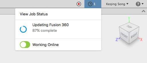
Next time you restart after we’ve pushed a product update, you’ll see a “1” next to the clock icon. (It’s pretty subtle, but that’s the idea.) Click it and you’ll see either the update happening in the background, or that it’s already landed, ready for you to take at your convenience.
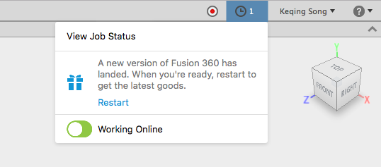
Convenience – that’s what we’re striving for. Work through updates like they’re not even happening. If you’re not ready to take the update, you don’t have to. Continue to work until you’re ready to restart, then click on “Restart” and you’ll be up-to-date.
Collaboration
We’re making good progress on core data management tools mentioned in our recent roadmap post. Although this update doesn’t include any of those features within Fusion 360, our data and collaboration experience via web browser, Fusion Team, has some new goodies in store.
New! Fusion Team markup tools
Previously if you were reviewing a model view through the web 3D viewer and wanted to mark up an area of the design for feedback, you only had access to one line tool (Arrow) and 5 types of area selections (Rectangle, Ellipse, Cloud, Custom Cloud, and Polygon). There are now a few more handy tool types for you to use.
New! Line tool and Line Style Controls
The Arrow line tool got a new roommate: the Line tool. It’s like the Arrow tool, but without the arrow. There’s also a handy Style tool for you to tweak the color, thickness, and opacity of the line.
New! Callout tools
Next to the Area Selection tools, there are new Callout tools. This makes it easier for you to highlight an area and add notes to it, all one command.
New! Text Styles

Just like line styles, you can tweak the style of your callout box, background color, background opacity, as well as text style, color, and size.
Notable bug fixes:
- The Project Transfer option was missing in personal hub “Settings” panel. Now it’s back.
- Moving folders within a project failed if the folder contained Fusion 360 designs that had relationships across folders. This is fixed.
- Inviting a team member failed when Admin Only Invite was the law of the land. Now the invite will send, but will still require admin approval.
- Invites failed when ‘About me’ section was lengthy. Now invites work regardless of how long your bio is.
- Comments did not get saved if the comments size (including screen capture) exceeded 1 MB. Now they save just fine.
Rendering & Graphics
Along with a couple of fixes, we’ve introduced a new command that enables transparent materials to work better with each other, resulting in more realistic renderings!
New! Dielectrics Priority Control
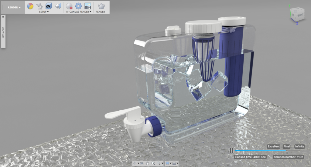
Water purifier model designed by Sergio Hernã¡ndez
It all started with this forum thread. Now when you’re in the Rendering workspace, you can right-click on a component and find an option called Dielectric Priority Control. Sounds fancy right? Well it kind of is.
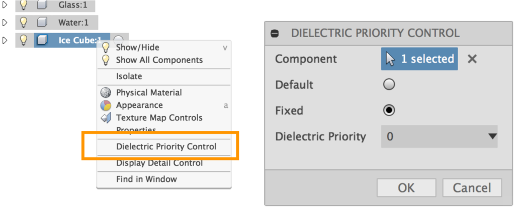
Nested Dielectrics is a solution for generating more realistic renderings with models that contain refractive materials, especially when one is enclosed in another one. Think of ice cubes in a glass of water. Previously, transparent bodies would just disappear when they are overlapping each other. You’d have to make boolean cuts so that the tool body (ice) is “nested” within the target body (water) to get the right effect. Now you can model your designs as they exist in the real life, and modify the transparency priority of each body (or dielectrics) so that the refractions look on point.
Check out this blog post on the nitty gritty details and how to best use this feature tomorrow. Check back then to learn more
Other notable fixes:
- Deleting named view renderings issue
You know how every design has a default set of named views and that these views are automatically rendered in your render gallery? Well Apvdm3 found out that if you wanted to delete these renderings from your render gallery, you could totally do it, but Fusion 360 will freeze when you try to delete the last one (whichever one that may be). After we spent some time with it, we learned that it was scared of you having an empty gallery and it didn’t know what to do. Now, Fusion 360 will no longer be scared, and is better at managing your gallery, regardless of whether it is empty or not. - Brep body still visible in Sculpt mode issue
We fixed this issue before, but it has come back in another form. This time, the bug got into our graphics department. We called the terminator and was able to get rid of it once and for all.
Simulation
Meanwhile in Simulation, we’ve added new nonlinear advanced material models, and streamlined how results are shown, giving you more control over what’s most important to you.
New! Advanced Material Models
We added 3 new advanced material models for Simulation: Temperature Dependent Isotropic, Elasto-Plastic and Mooney Rivlin. These material models will allow users to unlock additional power from the solvers by providing more accurate material data for more realistic simulations. So what are they? Funny you should ask :).
-
Temperature Dependent Isotropic
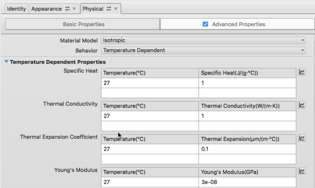
This material will allow you to define temperature dependent material properties such as Specific Heat, Thermal Conductivity, Young’s Modulus, etc.. for Thermal and Thermal Stress studies.
-
Nonlinear Elasto-plastic
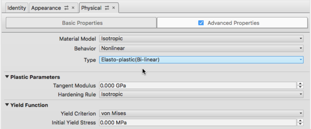
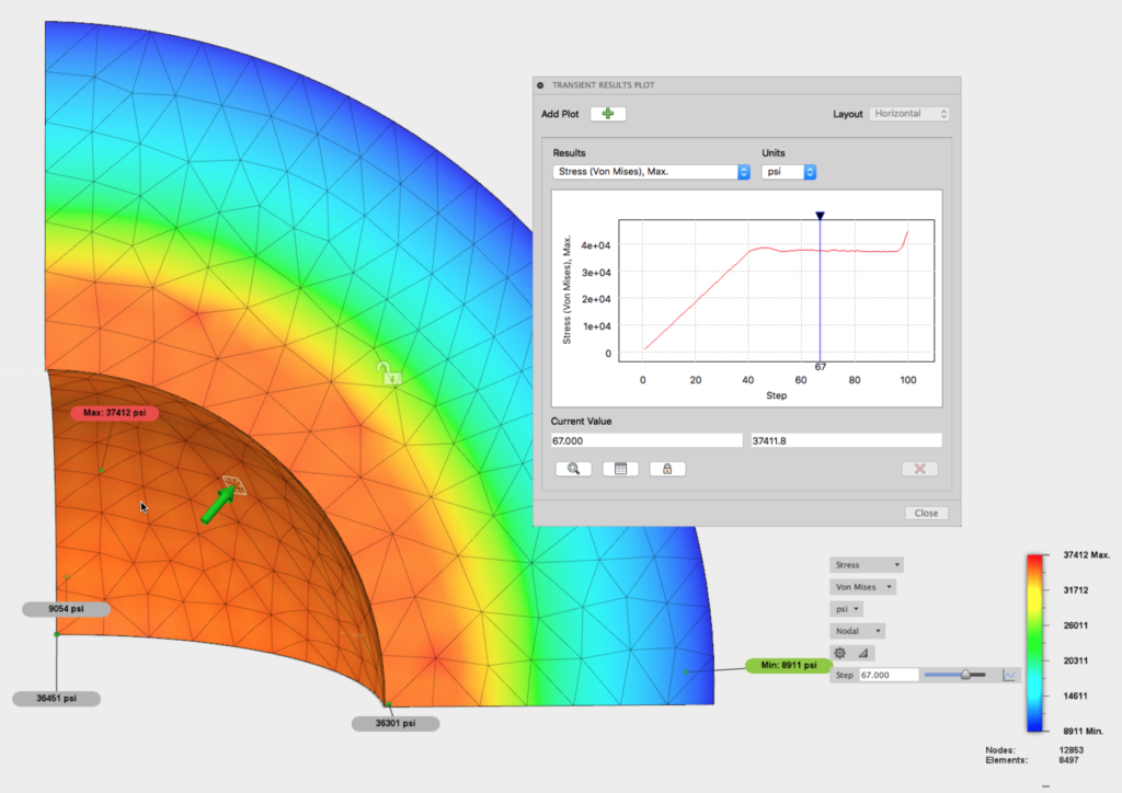
The Elasto-Plastic material model is a simplified nonlinear material model that will allow you to define post-yield behavior with a single value known as the Tangent Modulus, rather than having to define a stress-strain curve.
-
Mooney Rivlin
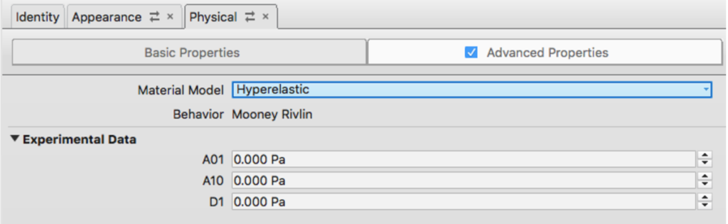

The Mooney Rivlin material model will allow users to more accurately simulate rubber materials, especially when large amounts of stretch or deformation are present.
-
Here’s how to get to them
If you don’t already know the steps to get to these material models, it can be a bit of a treasure hunt. Let me walk you through the four steps.
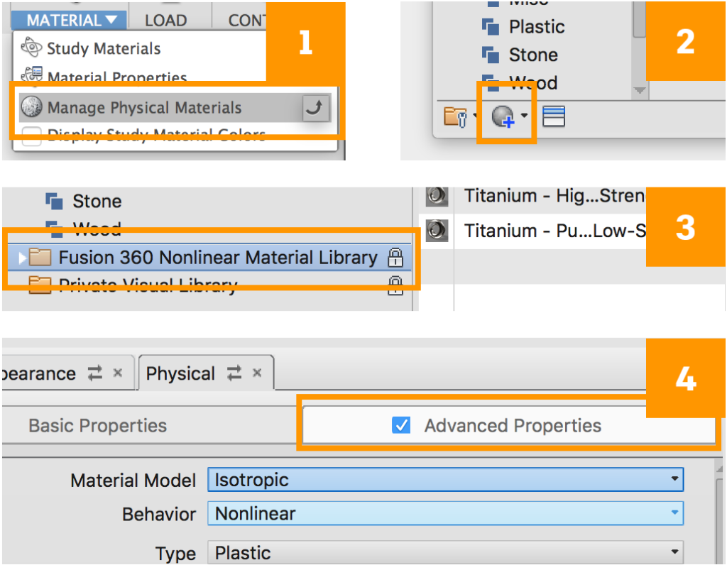
Step 1: Go to Material > Manage Physical Materials.
Step 2: At the bottom left corner, click on the Create new material icon.
Step 3: browse to the Fusion 360 Nonlinear Material Library and pick a material to start with. Any will do. Double click to select it.
Step 4: Check and hope over to the Advanced Properties tab. Material Model and Behavior drop-down menus are where you can access these material settings.
When these materials are assigned in their respective study types, the advanced properties will be used automatically for the simulation.
Improved! Streamlined Results Details
Now when you run a Linear Static Stress study on your design, you’ll be able to get a more streamlined presentation of your study results. Results Details will now include helpful tips and recommendations for over-designed, good, marginal and bad scenarios. We also made it easier for you to highlight specific areas of the model where failure could occur based on your setup. You can define custom ranges for how the designed will be assessed.
Keep in mind that the assessment you conduct depends entirely on how well you’ve set it up, so remember, garbage in, garbage out! A good set up may take some time to prepare, but the results are worth it.
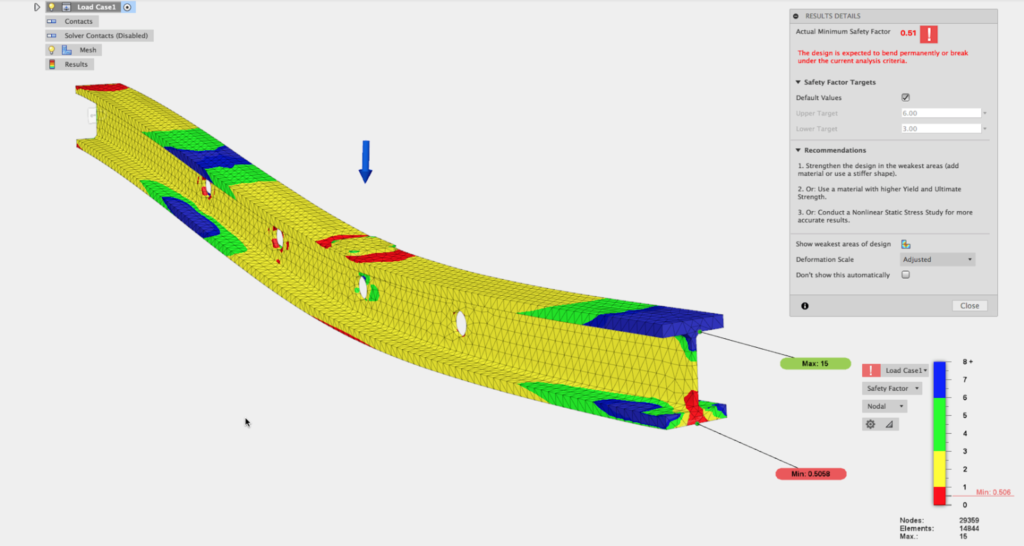
The is the default view, with Min to Max fully visualized.
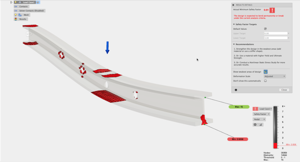
This is the view of the weakest areas
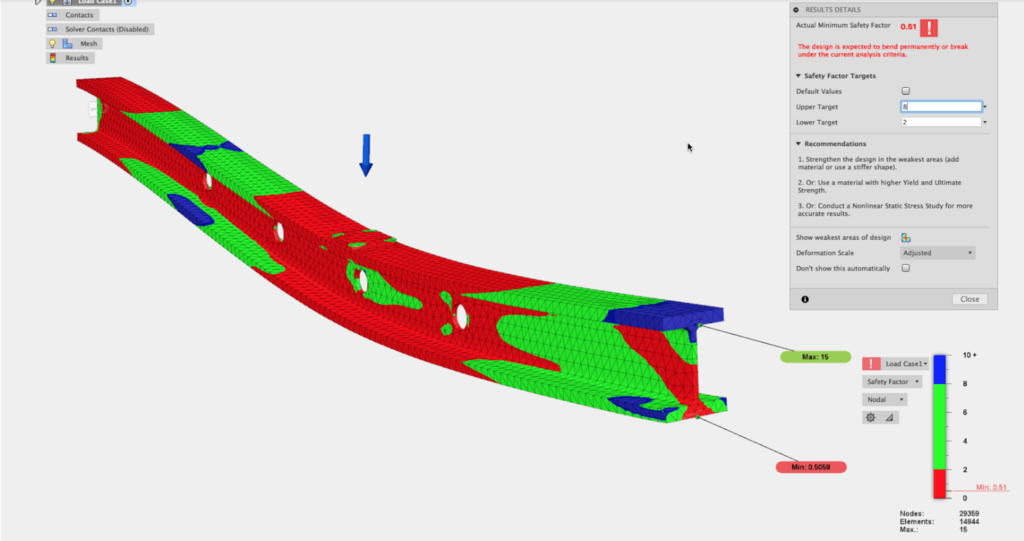
This is a view of a custom range for Factor of Safety.
Improved! New Bolt Connector Color Scheme
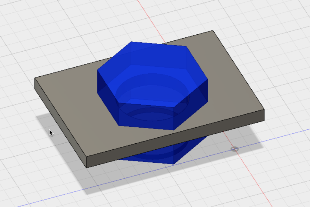
Bolt connectors were previously being colored based on their material, which often had them blending in with the model, making it hard to identify them from the rest of the model.
Now they use a basic, blue color with level of transparency to make them stand apart from the physical parts in the model.
Other notable fixes:
- Singularity Error issue
roseR2YZL ran into an issue where adding an thermal stress study to a cloned static stress study made Fusion 360 unhappy, followed by a “singular geometry” error message. We dug into the code and found that it was related to how we were writing the Nastran file. This has been properly resolved. - Local solves being stuck issue
Our support team told us that a number of you have encountered a scenario where you local solves would never start. Apparently what you experienced was the effects of a previous cloud solve that failed and consequently clogged up the system. Our bad. We called the plumbers and now we’re better at dealing with failed solves it doesn’t create blockage again.
HSM CAM
The focus for this update around CAM is to fix outstanding issues and improve overall quality of life, especially for turning workflows.
Updated kernel
We updated our kernel for both Mac and Windows, and by doing so, we were able to fix some general stability and performance issues such as:
- Gouging in 2D Contour fixed
- Gouging/bad toolpaths in Turning Profile fixed
- A “CAM kernel died unexpectedly” error in 2D Adaptive Clearing fixed
Improved! Turning
We updated our Fusion 360 Turning Help Documentation! Make sure to check it out in the help.
- Rapid Retract option now available in the Passes tab for Part, Single Groove, and Grooving.
- Reduced feedrate for part snow works with feed per revolution.
- Dwelling at the bottom of a toolpath before retracting now available for Single Groove, so you can rest assured that the part looks clean and finished. Please note that this functionality is still in beta – you can turn it on and try it by to text command “cam.betamode /on”.
- Previously, tool clearance was the same for frontside and backside by default. With our updated kernel, you can now enter a different backside tool clearance than your frontside tool clearance.
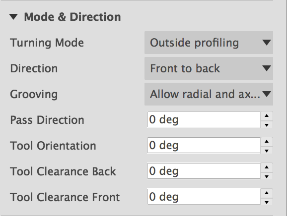
- Stock to leave is now split in two separate settings, for all turning operations where this setting makes sense, since the required tolerances and finishes are often very different in the radial and axial directions.
- We were finally able to fix this weird pecking issue during a final finishing pass around a fillet.
Other notable fixes:
- There were some wonkiness with how our selection chaining was working. There cases where parts of a continuous edge got left out of a selection set. Other times, certain contours were selectable. We tweaked our algorithms and now everything should working as expected.
- Waterjet no longer does inside > ordering for etch cutting mode.
- A weird “Create model option” dialog popped up when you moved from the Sheet Metal workspace to the CAM workspace with sheetmetal flat pattern open. https://jira.autodesk.com/browse/CAM-7317
- friesendrywall reported this “invalid or does not exist” message appearing every time he does a post process. This happened due to a folder name change. We got this sorted out.
- There was an issue where existing Sculpt bodies didn’t show up in the browser when you switched to the CAM workspace. Now they come over as expected.
- Similar to the sculpt body issue, some mesh bodies didn’t come over either. Our bad. This is now fixed as well.
- Macca5 reported an issue where sideways turn-groove wasn’t working correctly. The software made the tool spent a lot of time cutting material that was already cut, thus it was just cutting air. We dug into this and sure enough, we found a grooving bug. This is now fixed.
- ARTHUR-HM noted that he was loosing geometry references after regenerating a Spiral toolpath. Apparently, Spiral operations was having trouble retaining model surfaces between document sessions. We think we have this fixed, but would like you to try this and see if it still happens.
- Scott Moyse gave us notified us that when he was creating a custom turning tool in the tool library, he noticed that the tool image had the wrong proportions and did not match the dimensions he had entered in the entry fields. Thanks for the heads up Scott, we got this sorted for Fusion 360 and HSMWorks.
2D Drawings
We’ve been making good progress here, and continue to work towards delivering valuable features we’ve talked about in our most recent 2D drawings roadmap update. Here are some new goodies fresh out of the oven!
New! Edge Extension Tool
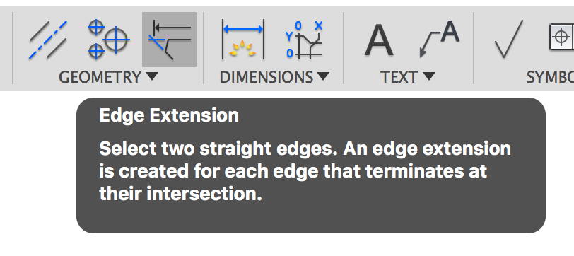
There is now a new tool in the Geometry section of the 2D drawings toolbar called Edge Extension. This tool enables you to create an edge extension for two intersecting edges (that are not touching) within any existing drawing view. And yes, it’s also associative, meaning that it’ll update if your geometry changes.
Edge extensions are helpful if you want to easily visualize where the intersection is between 2 lines, so that if you want to put a dimension between 2 intersections, you can easily snap to them. Also they just look cool on your drawings.
New! Output PDF using range or sheet selection
Now when you’re exporting your multi-sheet drawings as PDF, you can get enter a specific range of sheets to output. Under the Sheets drop-down menu, Select Range and enter the sheets you want to be included.
Another way to do this is by selecting the sheets themselves (CMD + click for Mac or CTRL + click for Windows) and then right-clicking on the selection to get Output PDF.
New! Lineweight control on output
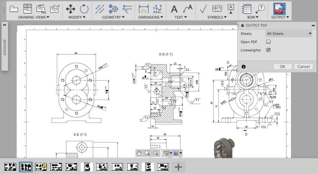
Hooray! This has been much discussed and highly requested. Sometimes when you output your drawing as PDF, there are lines that are way too thick. Now, you have the (much needed) option to turn on/off line weights, so your lines on your exported PDF have a thinner line weight. Winning.
Improved! Renumber Balloons
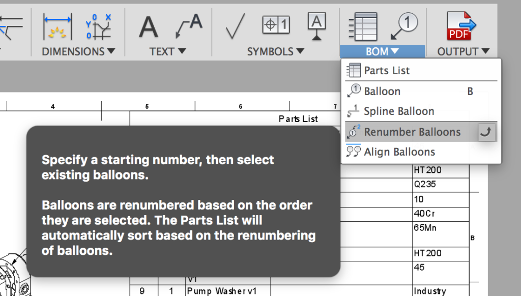
Previously if you had multiple callouts on a group of components, you had to renumber them individually, which can be a huge time-suck. Now when you select one of those balloons to renumber, the Renumber Balloons tool will automatically highlight all other balloons on the drawing with same item number. This makes sure that you don’t miss out on any balloon while re-numbering all your balloons.
Notable fixes:
- We fixed an issue where some of our European and Asian users have encountered Fusion 360 crashing when they are running the software in a resolution lower than 1024 x 768.
- Claybuddy reported an issue where the drawings he created included incorrect components. Ones that were suppressed were also carried over to the drawings, which shouldn’t of happened. Now it won’t.
- PhilProcarioJr found instances where editing custom tables caused Fusion 360 to lock up. We’re glad to report that this issue has been resolved.
- Related to the suppressed component issue, Ellworx pointed out that he was experiencing instances where Fusion 360 froze when he was switching from one sheet to another. Apparently Fusion 360 took awhile to figure out what components to show and what not to show. Now switching from sheet to sheet is instant.
- We’ve been tracking crashes issues that resulted from checking/unchecking entities in the Objects to Cut list of Section View. We tweaked it’s performance, gave it a tune-up and now it’s running like butter.
Previews
We are adding more and more people in the sheet metal preview workspace everyday, and have made progress on some core sheet metal functionality, extending its capabilities into the 2D Drawings workspace.
New in Preview! Sheet metal flat patterns now available
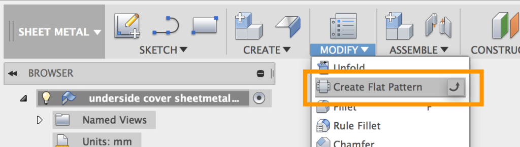
You can now create flat patterns of your sheetmetal designs! Access it under the Modify drop-down menu in your sheet metal preview workspace. We made a recent post about it that dives deeper into the details, so be sure to check it out!
That wraps up this update!
Make sure to watch the video to see all these enhancements in action!!!
As always, we look forward to hearing about your experiences with this update. Cheers and get cracking!
Keqing and the Fusion 360 team