See V.2.0.11685 improvements and fixes here

Note: In this edition of the What’s New blog post, you’ll notice a slight update in how we present the content. With Fusion 360 encompassing so many areas of expertise, our What’s New blog posts have become increasingly longer and longer, which is not ideal. That’s why for this November update, we’re going to focus on the major highlights.
Our goal here is to keep these product update blog posts as short, concise, and tight, so you can know what’s new as quickly as possible. If you do want to spend a little more time learning about improvements and bug fixes, we included a link to a forum thread at the bottom of this post that contains all those goodies for you to dive into. Thanks for your continued support! We’d love to hear what you think about this new format! And with that, on with the show.
Usability
New 3DConnexion SpaceMouse SDK Out-of-Preview (Windows Only)
After spending some time as a Preview feature, we are delighted to announce that Fusion 360 now features the latest SpaceMouse SDK V.4.0 on Windows, supporting features such as Lock Horizon. Previously available to try as a Preview feature, we took your feedback, worked with our partners at 3DConnexion, improved the preview, and made this production experience better and more seamless than ever. Please note that macOS is still on v3 of the SDK.
Fusion 360 now supports Windows 11 and macOS Monterey
Every new version of an operating system comes with a slew of updates to our services and how Fusion 360 runs. We’re happy to announce that Fusion 360 is officially supported on Windows 11 and macOS Monterey.
See more improvements and fixes
Electronics Design
Add 3D models to parts directly in the Schematic or PCB Editor
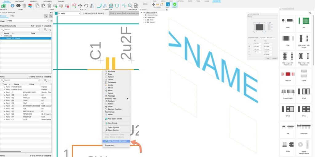
In Fusion 360, you can view and edit your PCB in the 3D Model space in a matter of moments. Using library parts that have 3D models assigned to the footprint is the most effective way to work in the electronic design space, but there will be times the parts you used had did not have a 3D model available, resulting in a default 3D grey box. To add a 3D model to the footprint would constitute editing the library and adding the 3D model in the library editor workspace. With this update, you have the convenience of mapping or creating a 3D model for your parts directly from the PCB or the schematic workspaces.
Sketch Circles can now be used to as holes in the 3D PCB
Originally holes you defined in the Sketch environment in the Design workspace were exposed as circles on the Dimension layer in Electronics Design. We have Improved this experience by replacing the circle for holes in the PCB, defining a proper hole-to-hole relationship for correct manufacturing output.
Template for DIP socket package in the Package Editor
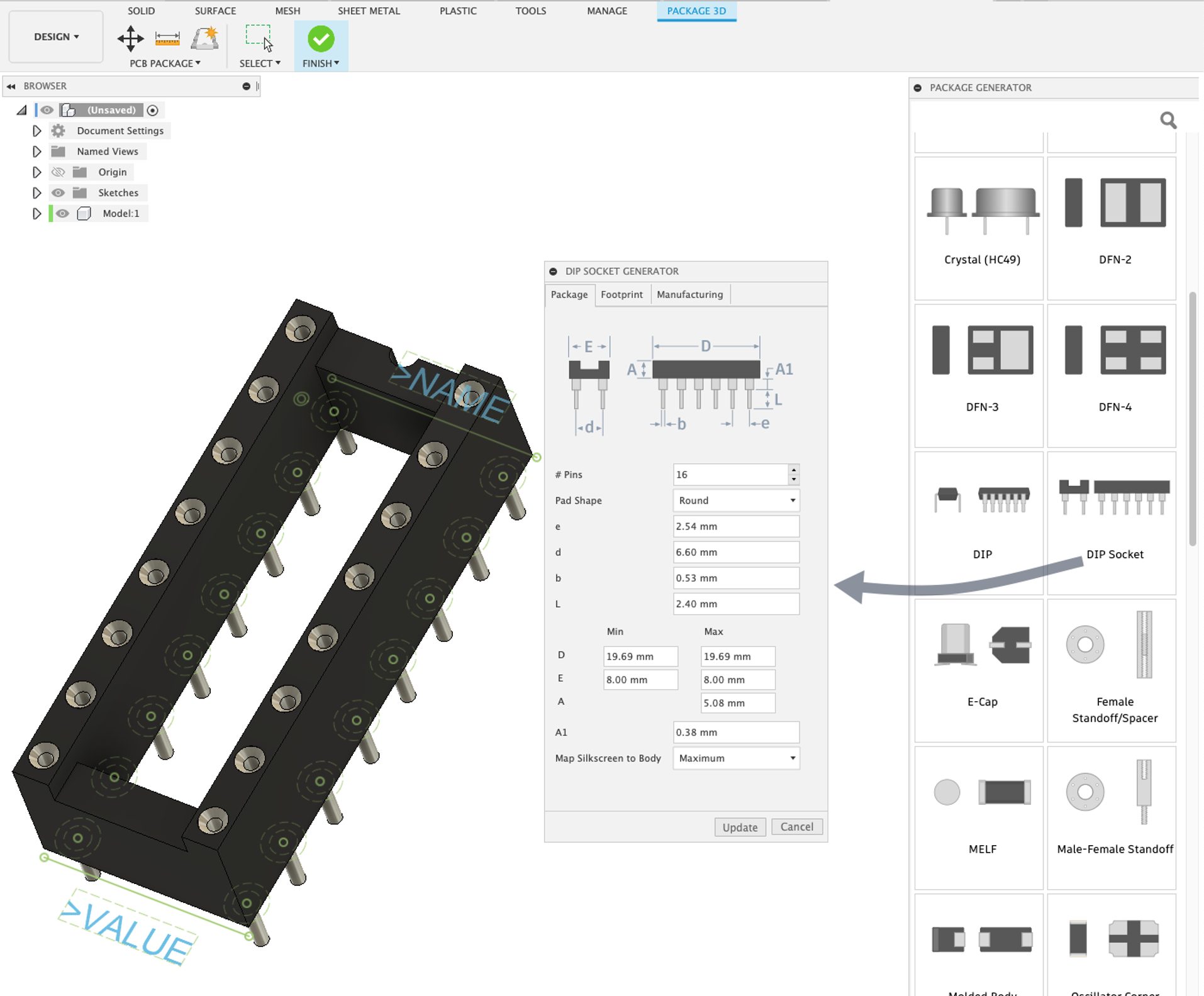
We have added a new package type, DIP Socket, commonly used on designs that require the component to be easily replaced, such as programmable devices. In this release, we support Open frame types, and we are also planning to cover the additional Socket types in the future.
Coming soon: Direct link from Tinkercad Circuits into Fusion 360 for electronic designs
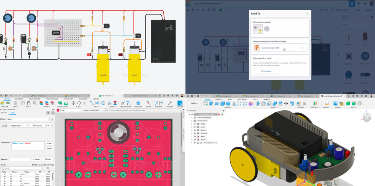
Tinkercad Circuits has become a massively used tool for electronic design and simulation at high schools and some colleges. Its shallow learning curve is ideal for beginners. Beginning 12/6, Tinkercad will provide a Send To option on the Tinkercad Circuits space that will allow users to directly send all components in their design along with a schematic into Fusion 360, where they will find all components already mapped in Fusion 360 (including a 3D representation for the 3D Board, available in the parts library). You can then continue all the necessary work to get a PCB in Fusion 360 (routing, defining which side of the board you need to place the different objects, manufacturing the PCB, etc.).
New library Parts: IC_Wireless_RF
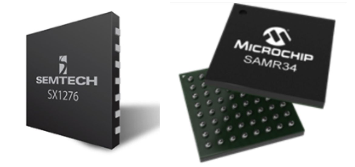
Popular Lora chips (IC_Wireless-RF library) from Semtech, Microchip which are present in Lora Modules, have been widely used for IoT applications. LoRa modules are commonly used for applications that transmit small chunks of data with low bit rates, making it ideal for actuators and sensors to operate in low power mode. Now available in the Electronics library, these IC parts will be useful when you decide to develop your own custom board.
Drawing & Documentation
Manage Extension Model Properties now supported in Title block
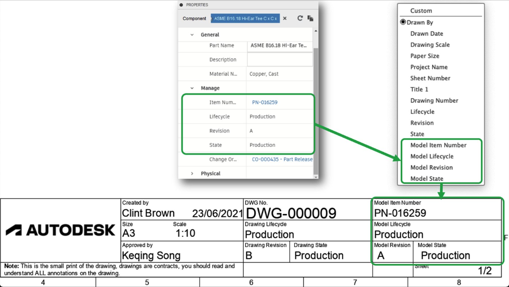
The Attributes in your drawing templates support properties from the Manage Extension. These properties are “Drawing Number,” “Lifecycle,” “Revision,” and “State.” If you are using Manage Extension, these attributes will be automatically populated with information from Fusion Manage Extension.
We have also expanded the Manage Extension attributes to include properties from the model, such as Model Item Number, Model Lifecycle, Model Revision, and Model State. Smart rules control the information displayed in the title block. For instance, the overall component properties are displayed if the drawing sheet contains views of multiple components. However, if a single part is shown on a drawing sheet, the Manage Extension properties displayed are specific to that part.
See more Drawings, improvements, and fixes.
Manufacture
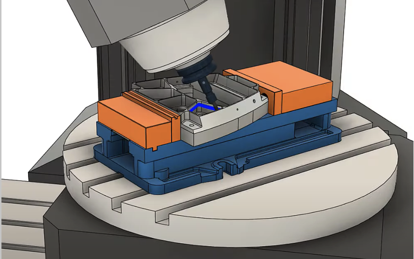
Now out-of-preview: Machine Simulation and Builder
After being in Public Preview for a while, we’re excited to say that the ability to build your own CNC machine with Machine Builder and simulate it in context to the toolpaths with Machine Simulation is now available as a production feature. We’ve improved the performance too, with a faster loading time. To learn more about the benefits of Machine Simulation and how you can build your own machines within Fusion 360, check out this video: Fusion 360 Machine Simulation – Machine Builder.
Rest Machining for Flat strategies
For those of you using Flat machining strategies, you’ll be glad to know that the Rest Machining option is now available in the Geometry tab. Rest, which stands for Remain Stock, limits the operation to only remove material that a previous tool/operation could not remove. With this option enabled, you’ll have the ability to use the most efficient tooling and still complete the part to the right specification.
Automatic Collision Avoidance for 4 Axis Rotary
Available in other strategies like Steep & Shallow, Collision Avoidance now comes to 4 Axis Rotary. Located under the multi-axis tab in the Rotary command dialog, turning this on will automatically tilt the tool around the rotary axis to avoid collision between the shaft or holder and part. This ensures a more autonomous toolpath strategy that should save you on programming time so that you can make the most out of your machines.
Ability to Machine Under Cut Regions for Steep & Shallow
The Steep & Shallow strategy just got even smarter, and it now can machine under-cut regions in your part. This furthers the automation programming toolpaths for complex geometry. The ability currently supports 3-axis Lollipop or slot mill and all 5-axis milling tools. Note that your Threshold angle must be set to 0 for this work.
Post Processors, Machines, and Tooling
We’ve added a few new post processors to our post library:
Hurco Turning with WinMax control and the Meltio M450 metal additive printer (this post exports DED toolpaths using the additive FFF operations in gcode format).
See our Improvements and fixes forum thread for what’s new with existing post processors.
See our extensive list of post processors in our post library.
New self-paced learning for Manufacturing
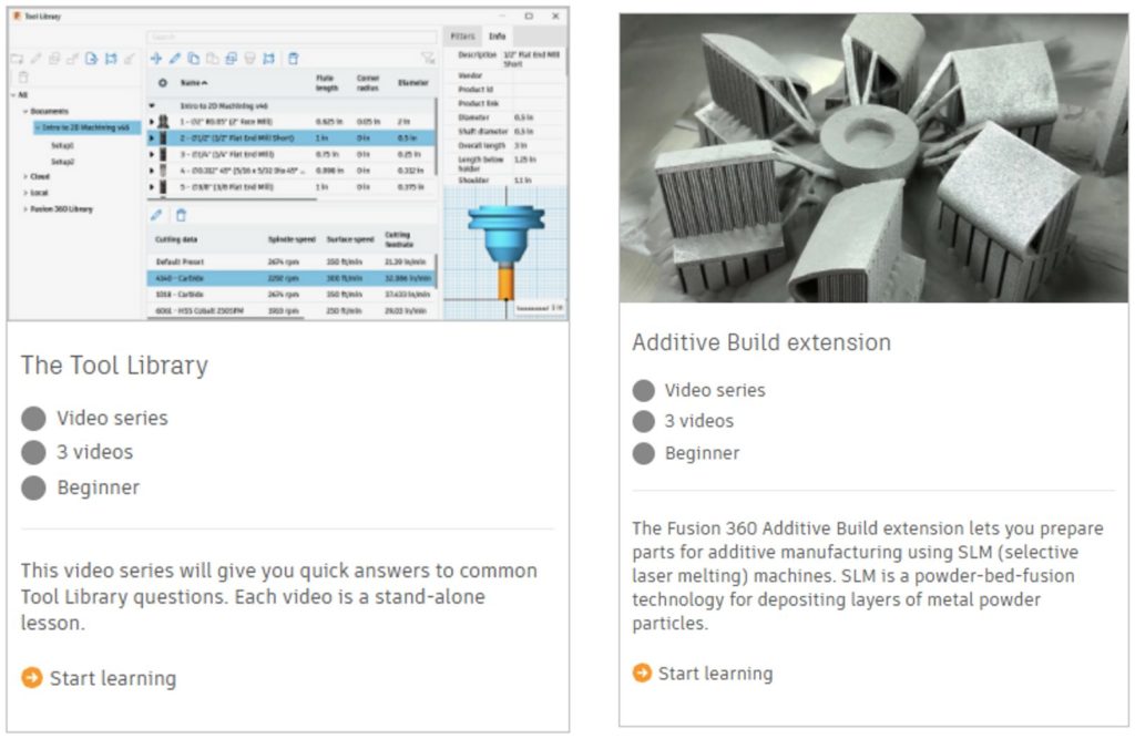
We added two new video series that are available on the Fusion 360 self-paced learning site to help you get started with different aspects of manufacturing: The Tool Library video series and The Additive Build Extension series.
- The Tool Library video series includes an overview of the Tool Library, Cutting-Data presets and calculating speeds & feeds in Fusion 360, and how to set up turning tools.
- The Additive Build Extension series walks you through the process of preparing a model for additive manufacture on an SLM (selective laser melting) machine.
New in Preview
Available on December 1: Component View in Fusion Team
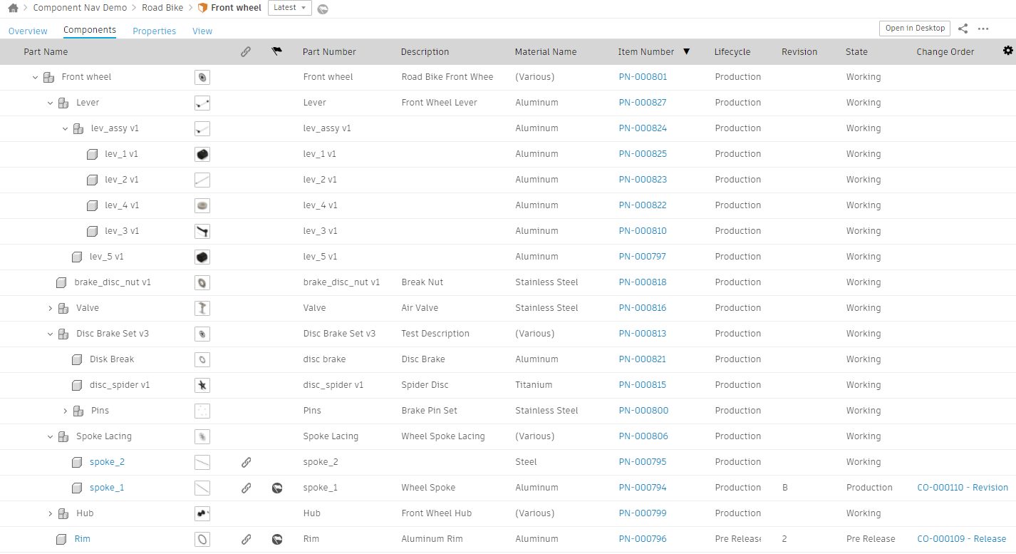
Have you ever wished you could look inside an assembly to see its internal components without having to open the entire file? This will soon be possible in Fusion Team with Component View – a view of an assembly’s structure, including all external and internal components, that exposes granular information about your design outside Fusion 360.
Component View is a tabular view of an assembly’s hierarchy, complete with all sub-assemblies and parts, nested in hierarchical order with corresponding thumbnail images. Component View lists each component’s metadata as columns in the table, and if you have Manage Extension, you can see each component’s Manage properties. The view also supports the Export of any component to the file format of your choice. Use it to quickly export internal components to STL for 3d printing or to extract internal components to share with external vendors.
Component View gives you access to internal components, assembly structure, and component data outside Fusion 360 so you can perform process, management, and collaboration workflows in a web-based environment that is practical and intuitive.
Learn More about Component View in Fusion Team
Import Product Manufacturing Information (PMI) Data on File Upload
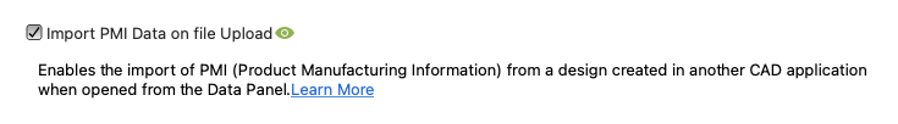
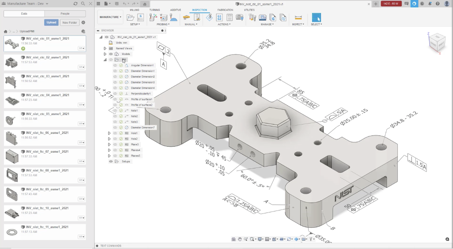
The “Import PMI Data on File Upload” preview feature lets you open designs created in other CAD applications and then visualize the designs’ PMI (product manufacturing information), making the original design intent clearer. To start trying this preview feature, first turn it on in the Preview Features section of your preferences. Then open the data panel and upload your designs containing PMI data. This preview currently supports Autodesk Inventor (.iam .ipt) and STEP files (.ste, .stp, .step). Once they are successfully uploaded, open them and switch to the Manufacture Workspace. You should be able to see a new entity in the browser called PMI.
Give it a spin and let us know what you think in the forum; we want to get your feedback on what works well, what’s missing, how you see this helping your workflows, and how you see this supporting your workflows.
Learn more about PMI
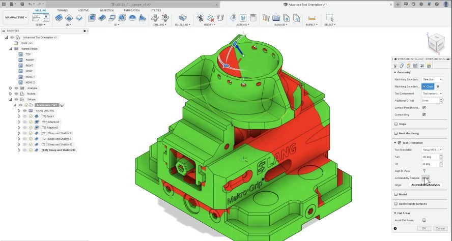
Accessibility Analysis for Tool Orientation

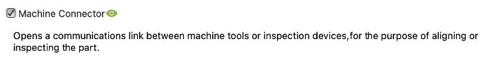
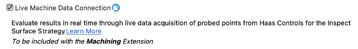
Machine Connector + Live Machine Data Connection for real-time part alignment
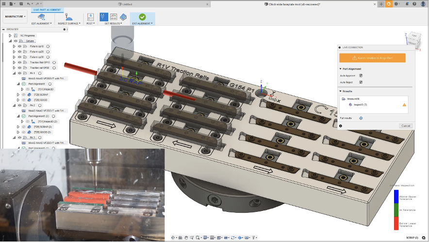
With these two previews turned on, you’ll be able to try the new Part alignment workflow. This allows you to use probing for the accurate setup of complex workpieces- typical applications are forgings and castings. Part alignment is faster, more accurate, and the time is more predictable than a manual setup.
The current alignment still needs a machine operator to be present. They will save a lot of time compared with a manual setup. However, at the end of the probing sequence, they still have to import the file of measured points, accept the results and post process an updated milling sequence with the updated alignment transformation. This preview experience currently only works for 3-axis translation on Haas machines. In the longer term, we plan to support other controls and axis rotations, but that adds a lot of new variables. Haas controls with 3-axis translation is what we can support today.
Trim tool-paths to boundary and plane

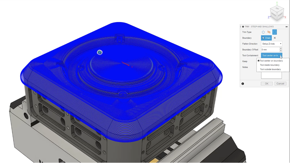
We introduced the Polygon Trim Type a while ago, but now you’ll have Plane and Boundary Trim Types to choose from.
Additive Multi-Axis Deposition toolpaths
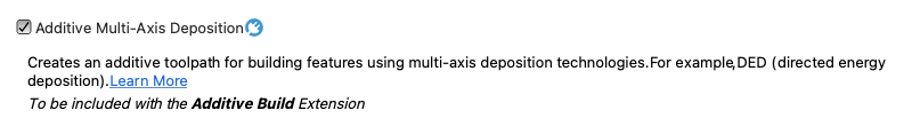
Now available as an extension preview is a brand new Additive Manufacturing toolpath strategy for multi-axis deposition. This new tool-pathing capability is primarily aimed at driving machines with Directed Energy Deposition capability. However, with some post processor modifications, it can also be used for other multi-axis deposition applications (e.g., FFF, large-scale AM, and concrete printing).
For those familiar with our machining workflow, the new multi-axis deposition workflow will feel very familiar. Along with the new toolpath, we have implemented a new tool type, “Deposition,” to store all your process parameters.
Related to the release of this preview, Fusion 360 now includes its first Directed Energy Deposition (DED) platform, the Meltio M450. Using an “FFF” style workflow, the machine, post processor, and print setting (for 316 stainless steel initially) can be found in the relevant Fusion libraries.
Additive Extension: Meltio M450, first Directed Energy Deposition platform printer added to Machine Library
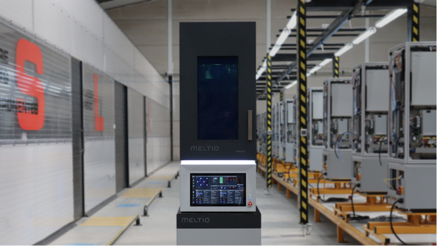
Fusion 360 now includes its very first Directed Energy Deposition (DED) platform, the Meltio M450. Using an “FFF” style workflow, the machine, post processor, and print setting (for 316 stainless steel initially) can be found in the relevant Fusion libraries. To try this functionality, head to the Preview Features section in your preferences and check the “Additive Multi-Axis Deposition” checkbox under Manufacture. Then in your setup, simply select our example machine named “Autodesk Generic DED”.
Learn more about additive multi-axis deposition
Improvements & Fixes
To learn more about other improvements that went into this update, our extended list of fixes to issues reported by you, as well as known issues, check out the related Improvements and Fixes forum thread below.
See improvements and fixes for this update
See past improvements and fixes threads