
Explore the November 2024 Fusion release, featuring improvements in Data Management, Design, Drawings, Electronics, Manufacturing, and more.
v.2.0.20981 – December 4, 2024
General:
- We fixed a variety of crashes in the Design and Manufacturing workspaces.
Data:
- We fixed an issue that caused the conversion of single storage/personal hubs to team hubs to not work as expected.
Drawings:
- We fixed an issue where certain drawings were unable to be opened due to unresolved external components.
v.2.0.20970 – November 27, 2024
General:
- We fixed an issue where the OK button was disabled when you went to save an existing design.
Design:
- We fixed an issue where editing the dimensions of a sketch would create warning messages in pre-existing modeling operations.
Manufacturing:
- We fixed a crash issue that occurred when inserting a partially threaded screw from McMaster-Carr.
v.2.0.20962 – November 25, 2024
Design:
- We fixed an issue where the camera orientation was lost when switching from the Animation workspace to the Design workspace.
Drawings:
- We fixed an issue causing Leader Notes containing part numbers to be incorrectly displayed.
Electronics:
- We fixed an issue in QuickRoute Guided where using the enter button did not commit route signals as expected.
Manufacturing:
- We fixed an issue where you were unable to add a tool to the tool library when the name ended with a space.
- We fixed an issue in Blend where the Maximum Spacing option was not shown when Stepover Calculation was set to “From Tip of Tool” and “Evenly Spaced Points” was selected as the Smoothing option.
General:
- We fixed an issue where out-of-date Windows 11 builds were being incorrectly detected as Windows 10 in the orange warning banner. The banner message was otherwise displaying as expected. If you received this banner, it is recommended you update to Windows 11 22H2 or newer.
v.2.0.20948 – November 21, 2024
- We fixed an issue causing changes to the environment settings to be lost when a new Fusion session was launched.
- We fixed a crash issue that occurred while creating text in an automated drawing from a sheet metal design that does not have a flat pattern.
v.2.0.20754 – November 18, 2024
Table of Contents
- Highlights
- Upcoming Changes
- Data Management
- Design
- Drawings
- Electronics
- Simulation
- Manufacturing
- API
- Fixes
- Insider Program
Highlights
The last major update of the year is here, bringing a range of new features and enhancements designed to revolutionize how you work. Let’s take a look at some of the highlights from this release.
Usability and Data Management
- Copy Design with Drawings with the Fusion web client
- New Search Enhancements for Home tab
- Configurable Item Numbering Schemes (Manage Extension)
- Various Performance Enhancements
Design
- New Edit Initial Position
- New Configure on the Fly
- New Configure Mesh Bodies
- Configurations Cloud Render Support
- Implicit Suppression in Configurations Table
- Form Subdivide improvement: Consistent Orientations
- Parametric Volumetric Lattices
- New Sketch Groups
- Rivets in Fastener Libraries
Drawings
- Support for Multiple Configurations in a Drawing
- Automated Drawings Views Optimization
Electronics
- Meander Improvement – Balancing Length of Signals
- Component Search Library Manager Improvement
- Custom Copper Clearance and Copper Width Rules for Quick-Route Tools.
- PCB Place Panel Improvements
- Search by Component Name in Library Manager
- Added Support for Construction Line in Align Command
Manufacturing
- Easier 4-axis Machining for 3D Milling Finishing Strategies
- Additive Manufacturing Process Simulation: Directional Part Removal from Build Plate
- Duplicate Components for 3D Printing
- New Leads and Links Modifications
- Reduced Whisper Cuts in 3D Adaptive Minor Stepdowns
- Visualization of Contact Normals
- Machine/Avoid Surface Support in Horizontal and Swarf strategies
Live with the Experts: What’s New in the November 2024 Release
Join us on Thursday, November 26, 2024 starting at 8:00 AM PST and 4:00 PM GMT for a 60-minute session going over the latest and greatest in Fusion.
Come learn about all the new functionality and tools now available in the November Fusion update in Design & Documentation, Manufacturing, Electronics, Generative Design, and Simulation.
During this 60-minute webinar, we’ll also dive into improvements around flexibility, control, and programming efficiency, show off tips & tricks, and open up the floor for LIVE Q&A.
Upcoming Changes
Important OS support information after March 2025
After March 2025 Fusion will no longer fully support macOS 12 Monterey. To continue developing Fusion with the latest advancements, we must stay current and phase out support for older OS versions. We understand that this change may require some time for you to adjust. That’s why we are letting you know now, so you have plenty of time to update your OS to the latest version.
New Standard regarding your Fusion Content
In August 2024, a new Fusion Content Storage Standard was introduced to protect and minimize how long we store your Fusion Content even after you are no longer subscribing to or using Fusion. To help ease the transition into this new Standard, the accessibility to any inactive Fusion hub that has reached the end of the relevant storage period won’t be impacted until, at the earliest, August 2025.
Learn more in the FAQ here.
Data Management
Configurable Item Numbering Schemes (Manage Extension)
Configurable numbering schemes enable organizations using the Manage Extension to define the format of their item numbers so that they match company standards. Administrators will find new tools to define their company numbering schemes in the Fusion web client. Once the schemes have been defined, you will then be able to select from a list of them while assigning numbers to their components, giving them the flexibility that they need when generating numbers.
Learn more about numbering schemes.
Copy with Drawings available in Fusion Web
In the Fusion Web client, it is now possible to copy a design and include its drawings. When copying a design file, you will be presented with a new screen where all the related design drawings are shown and an option to include the drawings. You will also be able to distinguish drawings that are out of date which will not be copied with the design.
Joining a Hub is Now Easier Than Ever
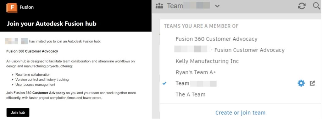
Previously, if you didn’t receive an email inviting you to join a hub or if the email got filtered from your inbox, you were unable to access the Fusion hub. Now we have conveniently added hubs that you have been invited to in our Fusion hub switcher and options to join on first use.
Exciting Enhancements Coming to Autodesk Assistant
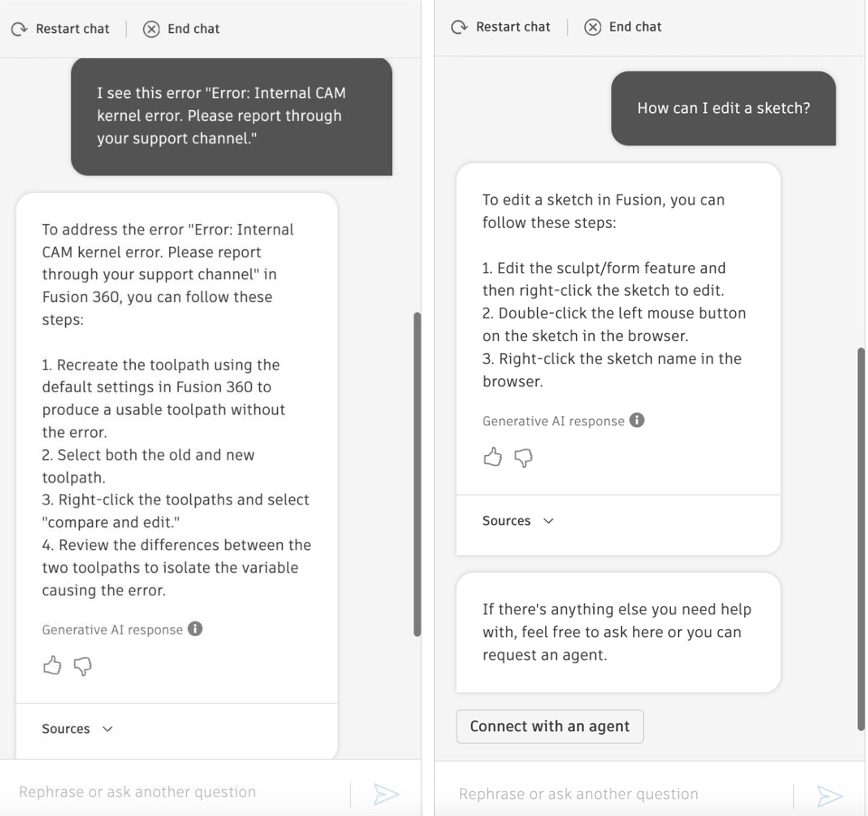
We’re thrilled to unveil upcoming enhancements to the Autodesk Assistant experience! These improvements are designed to make relevant Autodesk content more accessible than ever while you work in your Fusion workspaces. Our goal is to provide seamless access to support whenever you need it.
Our dedicated team has created a contextually personalized and conversational Autodesk Assistant experience. By integrating cutting-edge technologies such as Large Language Models (LLMs) and generative AI, we have significantly enhanced Autodesk Assistant’s capabilities.
Simply type a question to ask for help with troubleshooting an issue or find information on how to use product features all without leaving Fusion. With this new experience the Autodesk Assistant provides summarized responses or step-by-step guidance when it is confident that the content is relevant to the inquiry. This capability streamlines workflows by eliminating the need to sift through lengthy articles and improves user productivity by ensuring access to information directly within the Fusion canvas. Along with each generative response the Autodesk Assistant will indicate the content resources that were used in generating the information. If a summarized response is unable to be generated the Autodesk Assistant will continue to suggest relevant support articles.
These upgrades reflect our commitment to enhancing self-service and efficiently meeting your needs. With the introduction of specialized AI agents, you can expect significant improvements in terms of Autodesk Assistant’s capabilities moving forward. More to come!
Stay tuned for more updates and let us know how these enhancements impact your workflow.
Search Improvements
Search for Files in Home tab Based on Component Name and Part Number Properties
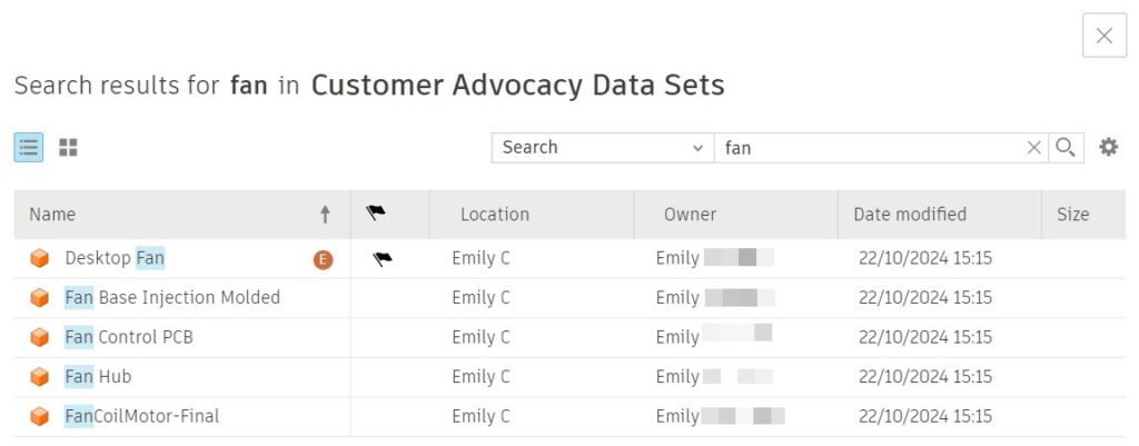
In the Home tab search, you can now search for files based on the exact Part number property value or with a “contains” search on the Component name property value. If a design matched against the Component name or Part number, the respective file would surface in the search results. Previously, you were only able to search for file names.
Note: If this enhancement is not immediately visible, do not worry. We’ll be releasing this functionality slowly over the next few weeks. So if you don’t see it today, you should be able to use the functionality very shortly. By adopting a staggered approach, we aim to seamlessly integrate this powerful feature into the Fusion ecosystem.
New Ability to Select Scope of Search in Home tab
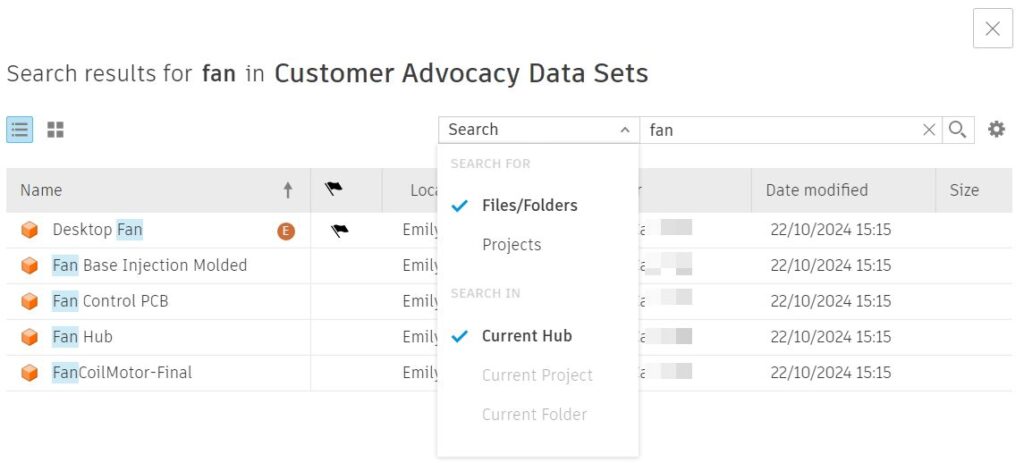
In the Fusion Home tab, it is now possible to limit the search scope before searching. You can search for files or folders in the current project or folder where you navigate to.
Performance
Each update we work to make Fusion faster and better than ever. By investing in performance, we’re committed to enhancing Fusion’s speed and ease of use with each release. This November we have so much to share with you. Here are some of our favorite performance enhancements:
Design Enhancements
- Properties, Center of Mass, and Drawing Workflows: Experience up to 3x performance improvement when showing properties, creating the center of mass, and creating drawings for large design files with numerous overrides.
- Component Pattern Creation: In the November release, creating component patterns for typical assembly design files is up to 40% faster compared to the September release.
- File Opening: Opening files saved between the January 2024 Fusion update and the October 2024 Fusion update is about 3.2x faster. This improvement is most noticeable in files with Manufacturing data, especially when the active workspace is not set to CAM.
Usability Enhancements
- Look At Command: The Look At command now supports selecting sketches or work plane nodes directly from the timeline.
- Select By Name: The “Select By Name” feature can now highlight and select components in the Browser even if the component is not visible.
Design
New Edit Initial Position [EDIP] – Unlocking the Fusion’s “One Free Move”
We are introducing a new feature “Edit Initial Position“, allowing you to modify the initial position of a component directly from the context menu.
Previously, when inserting a component into an assembly or creating a copy of an existing component, you positioned the instance exactly where you want it during the initial placement and once this position is confirmed, any further adjustments would generate a new move feature in the timeline. Once you position a component precisely during the initial placement after confirmation, changes to this position traditionally resulted in a new move feature being created in the timeline.
When you used “Ground To Parent” on an instance, the component would automatically move to its default(initial) position. Any downstream features that change the position of the component would not be considered. As a result, it was not possible to position a component anywhere other than the default and Ground To Parent that component.
The new functionality enables you to adjust the initial position without adding new features to the timeline, streamlining the design process. This capability is applicable in both Parametric and Direct Modeling environments, as well as in Edit in Place (EIP) mode and the PCB package generator workspace.
It’s important to note that “Edit Initial Position” is only available for components without any external geometric references, ensuring that modifications are clear and manageable. This feature significantly enhances the flexibility and usability of component positioning within assemblies.
New Sketch Groups
You can now create named groups within the Sketches node in the browser, making it easier to organize and sort your sketches. This is especially helpful in cases where you are working with complex models with many sketches. Within Sketch groups you will be able to move Sketches in or out of the Sketch Group, as well as rename and restructure the groups.
Groups can also be nested within each other to create sub-groups for improved structure. Drag and dropping the sketches and groups can also be used to reorganize the group structure.
Volumetric Lattices are Now Parametric (Design Extension)
Volumetric Lattices are now fully parametric. This means you will now see a Volumetric Lattice feature in the timeline, be able to edit values using the parameters table and create configurations which include lattice structures.
In the past, volumetric lattices were a non-parametric feature inside of Fusion. This had limitations and meant manual changes were needed when a design change was made upstream. With the November release, the Volumetric Lattice and the Create Mesh from Lattice commands are parametric, which means they will fit more seamlessly into your product development workflows.
We have also improved the visualization quality of Volumetric structures inside of Fusion. This will most clearly be seen by those of you who use the NTop For Fusion add-in, when importing complex geometries from NTop platform.
The Volumetric Lattice command is available via the Design Extension.
Insert Derive & Insert Component from Toolbar While In Offline Mode
We know it’s not always possible to be connected to Wifi, for those times where you are disconnected from the internet Fusion offline mode allows you to continue their design process. Within offline mode most design capabilities are available but insert of components and derives was not available. This release we expand the capabilities of offline mode by enabling these capabilities to provide a more complete offline design experience.
Learn more about Fusion Offline Mode.
Form Subdivide improvement: Consistent orientations
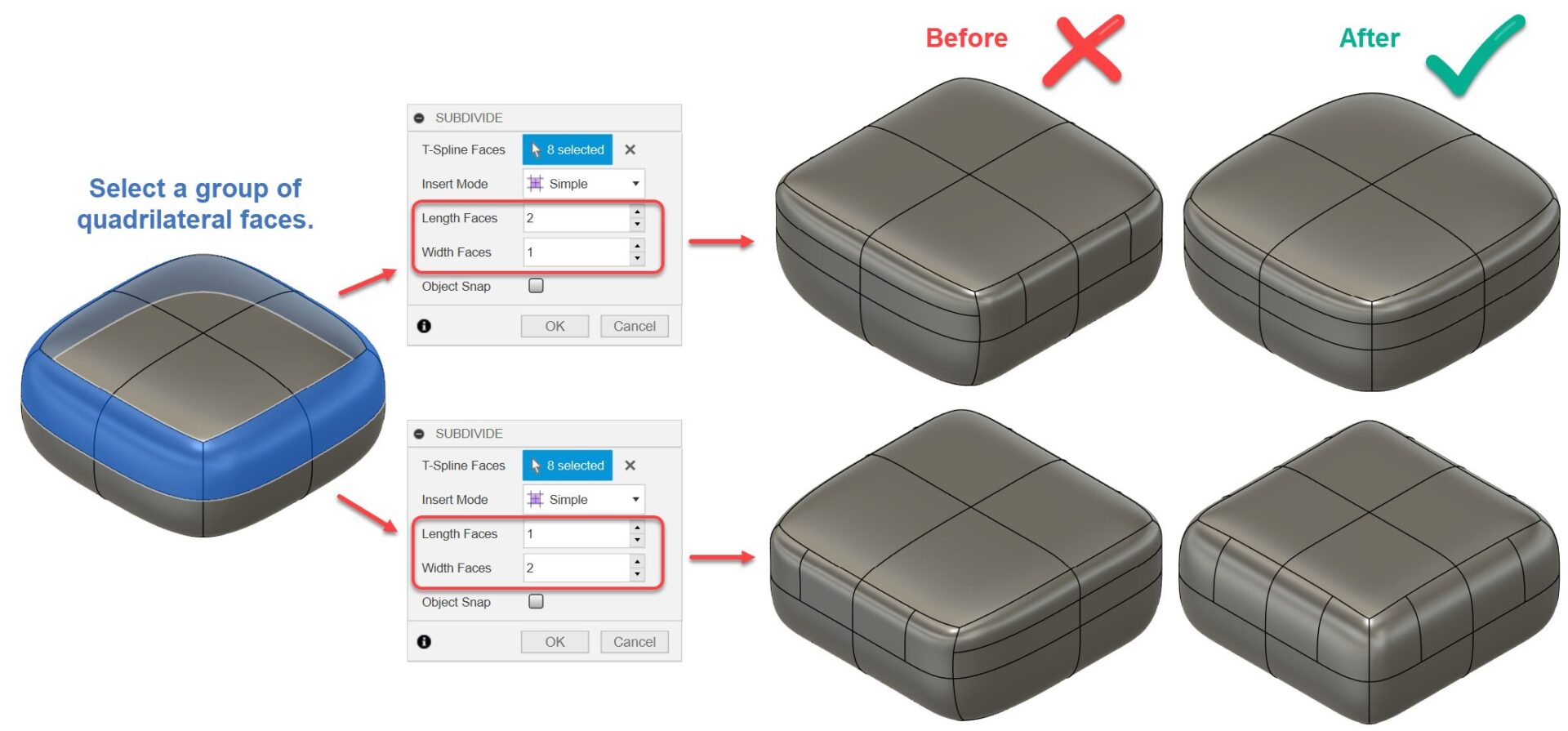
Design > Form > Modify > Subdivide
Previously, when you used Subdivide for a ring of quadrilateral faces, the direction of the divides was inconsistent. Now, Subdivide orients the divides consistently across the selected faces providing you a more predictable experience.
Improved Management of Disassociated Assembly Contexts
If an Assembly Context becomes disassociated from the driving assembly (due to designs being moved, copied, or deleted), then the link can be broken. Now, when breaking the link on an Assembly Context, cached bodies and sketches will be placed into new custom groups in the browser, so you can easily find and mange the geometry that was previously associated with Assembly Context.
If any Assembly Contexts have become disassociated due to copying or moving the driven component or driving assembly, then a warning will inform you about this and automate the cleanup of those Assembly Contexts.
Export Construction Curves as Dashed Lines while exporting Sketch to DXF
We heard feedback expressing the need for construction curves and lines to be exported as dashed lines in DXF files generated from Sketch. This highly requested feature is now included in our latest update.
Surface trim now available during edit in place
The surface trim command has been enabled during edit in place.
Fastener Library Improvements
New Rivets in Fastener Libraries
Each update our teams have been working hard to make Fasteners Libraries work better for you. To do this we’ve been listening to your feedback. This update we added a highly requested new category to Fasteners Library, Rivets. This means you will now be able to add Rivets to your assemblies using the fastener libraries automated workflow. This is a new category and will be seen alongside bolts, nuts, and washers. Within Rivets you will see over 70 different rivet families have been added.
Continuous Enhancements to Fasteners Library
We are thrilled to announce that within the November update, we’ve added 700 new families to our library. These new families are primarily based on ANSI/ASME standards. This enhancement comes directly from user-submitted requests, reflecting our commitment to listening to your needs and continuously improving our offerings. Your feedback has been instrumental in guiding these additions, and we are grateful for your active participation.
Configuration Enhancements
Configure On The Fly
In the November release of Fusion, we’re adding a Configure tab to some of the most-used modeling commands, to make it easier to configure aspects as you model without interrupting your design flow.
As you create or edit a configurable feature:
- Use the controls on the Feature tab as normal to define the feature
- Switch to the new Configure tab
- Check the aspects you want to configure
- Click OK to complete the command
Each aspect you checked is added as a column in the Configuration Table, and you can continue modeling without the need to switch contexts.
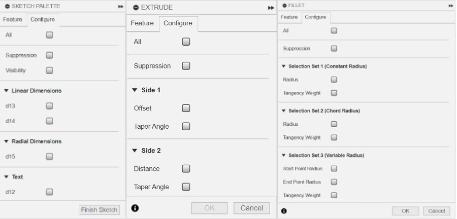
You can find the new contextual Configure tab in the following command dialogs
Solid:
- Extrude
- Revolve
- Sweep
- Loft
- Rib
- Web
- Emboss
- Box
- Cylinder
- Sphere
- Torus
- Coil
- Pipe
- Hole
- Fillet
- Chamfer
Surface:
- Extrude
- Revolve
- Sweep
- Loft
- Ruled
- Offset
- Boundary Fill
- Patch
Stay tuned as we support additional commands in future releases.
Learn more about Fusion Configurations
Implicit Suppression in Configuration Table
In the November release of Fusion, we’re enhancing the way we represent and treat implicitly suppressed features in the Configuration Table.
We added a third state to the table:
- Unsuppressed: feature is unsuppressed in this configuration.
- Suppressed: feature is explicitly suppressed in this configuration.
- Implicitly Suppressed: feature is implicitly suppressed by an upstream feature in this configuration.
Implicitly suppressed features are suppressed by an upstream feature, which may or may not be a configured feature. If you unsuppressed the upstream feature, the implicitly suppressed feature will return to its previous state. This provides clearer and more predictable implicit suppression behavior when working with configurations.
The suppression state for features in the inactive configuration rows are now accurately reflected as well, so you don’t have to activate a row to compute and understand the suppression states. We’ve also added tooltips to each suppression icon in the table to help you better understand suppression states and identify upstream dependencies for implicitly suppressed features.
Learn more about Configurable Aspects and how to Configure Feature Suppression in Fusion
New Configurability Support for Mesh Body Visibility/Appearance/Material
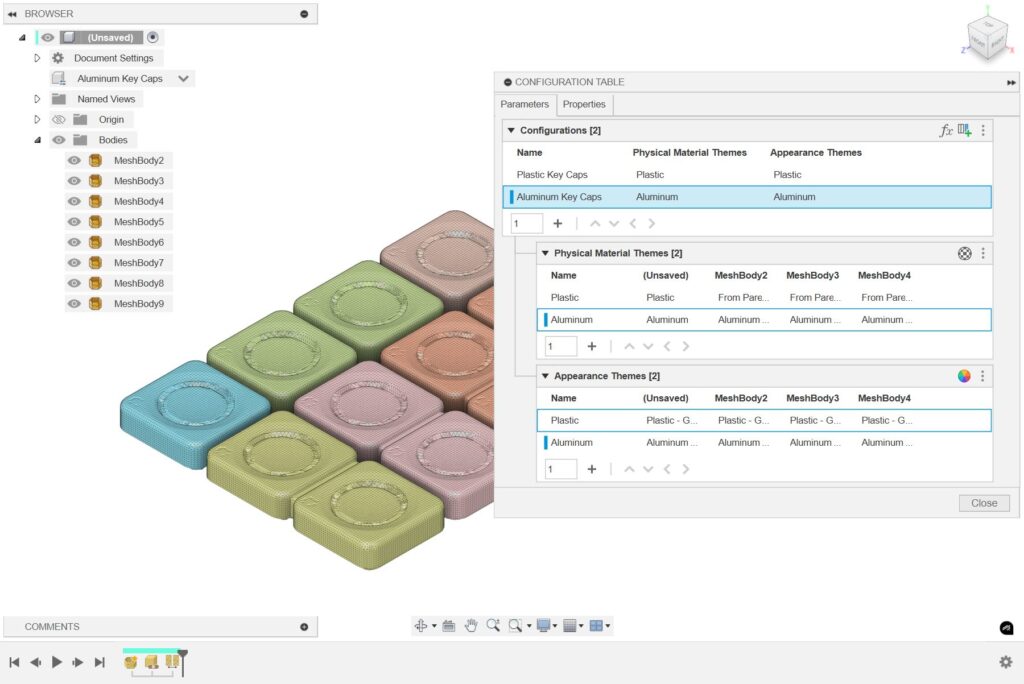
In the November release, we’re adding configurability support for Mesh bodies. Now you can configure the following aspect for Mesh bodies in a Configured Design:
- Physical Material
- Appearance
- Visibility
In Configuration Mode, click a mesh body in the Browser to display its Configure dialog. Check the aspects you want to configure, and they’re added as columns in the Configuration Table.
Learn more about Configurable Aspects in Fusion
Enhanced Support for Configurations in Cloud Render workflow

Up until now, if you wanted to create a set of rendered images for each of your configurations, you had to activate the configuration you want to render, save a new version of the Configured Design with it active, and then render your images. Then repeat the process for each configuration. This could be repetitive and required you to save a lot of unnecessary versions just to render your set of configurations.
In this release, we’re enhancing support for Configurations in the Render service. Now you can:
- Activate any configuration you want to create images
- Adjust the settings
- Render the image
- Then activate another configuration and repeat the process
All without saving unnecessary versions of the Configured Design in between each different configuration you need to render.
Learn how to Render Configurations in Fusion
Drawings
Support for Multiple Configurations in a Single Drawing Document
Up until now, when you documented your Configurations, you had to create and manage a separate Drawing document for each Configuration in the set.
In the November release, we’re adding support for multiple Configurations documented within a single Drawing:
- Create View Sets for 2 or more Configurations within the same Drawing document, as long as they’re siblings defined within the same Configured Design.
- You can even create View Sets for 2 or more Configurations on the same Sheet.
- Duplicate a sheet, and from the Browser or the right-click context menu on any View, use Switch Configuration to select a different Configuration.
- Set the new Scope option to View Set to switch only the configurations in the selected view set.
- Set Scope to Drawing to switch all views in the Drawing document.
Learn how to Create Drawings of Configurations in Fusion
New Automated Drawings Views Optimization
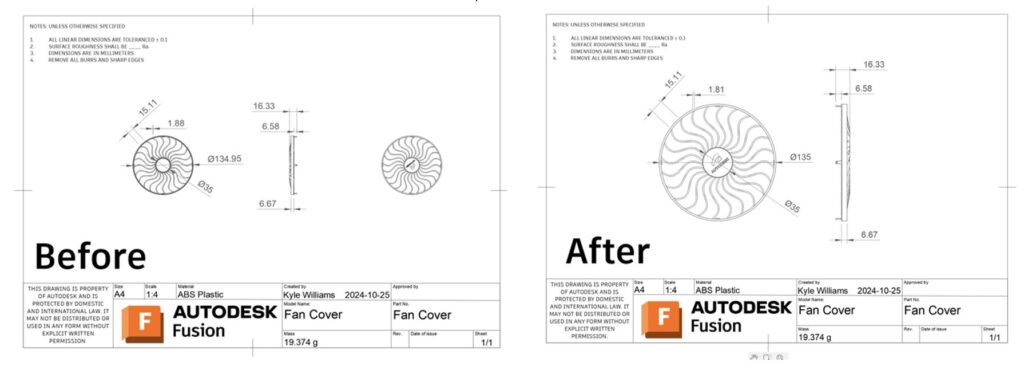
Earlier this year we introduced Automated Drawings, allowing you to create Drawing, sheets, views, dimensions for a design in just a few clicks. Since then we’ve heard some feedback on improving the views that get generated through automated process. We have now optimized automated views creation to avoid creating unwanted/similar views.
Improved Performance
Fusion Drawing will now default to using high performance graphics settings. This will help with drawing performance and stability particularly with more complex models
Electronics
Meander and QuickTune
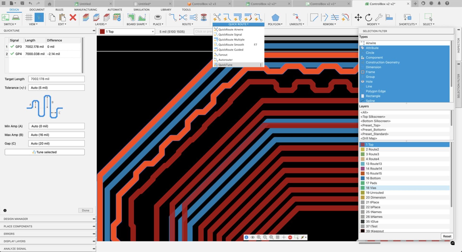
Meandering on a PCB involves shaping a trace into a wavy or serpentine path to increase its length. This is essential for balancing signal delays between traces and maintaining timing and signal integrity in high-speed circuits. This update features an intuitive interface for the Meander command, where you can specify the length, tolerance, and gap spacing. When working with differential pairs, the Meander command automatically adjusts to match the length of the longest trace, simplifying the design process.
QuickTune is an essential new addition to our Quickroute family. It allows you to quickly length-tune a single trace, differential pairs, or a group of traces, offering the flexibility to either match the longest trace or set a specific length. The interface also lets you define amplitude and gap spacing, giving you precise control over trace tuning and ensuring optimal signal alignment across your design.
Component Search by Name
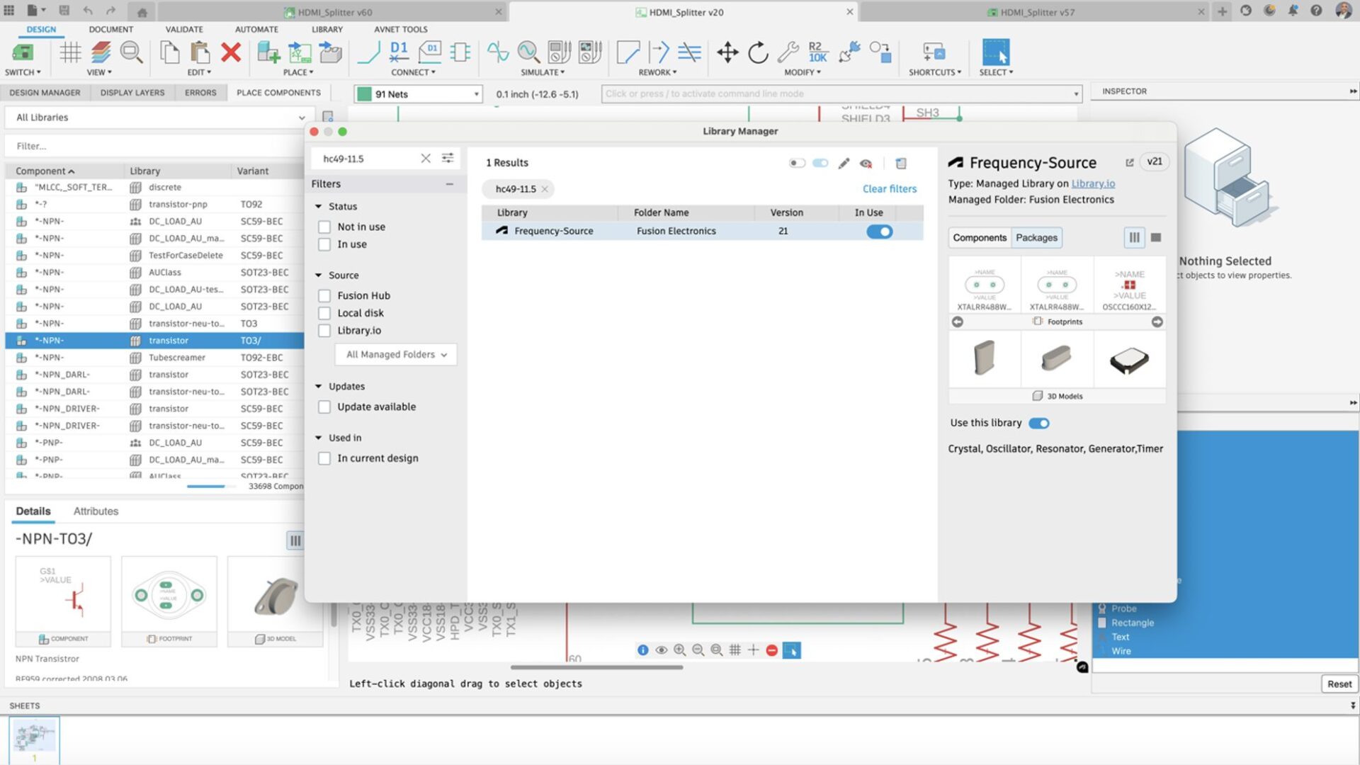
Finding the correct parts for your schematic Fusion design is essential; this Fusion update makes it even easier. Now, you can search for parts directly within the Library Manager, accessible from the Place Panel. Type the name of part of the name of the part you’re looking for in the Library Manager Filter, and you will get a list of libraries with that component. This feature is invaluable, especially when you want to use a part created by a specific librarian or supplier. With a clear view of all available options, selecting the ideal part for your design becomes simple and efficient, helping you save time and resources.
Improved + New Soldermask and Paste Stencil Support for Vias, Pads and SMD

The solder mask is a protective layer applied to a PCB to insulate the copper traces and prevent accidental solder bridging. The paste stencil is a thin metal sheet made by the board house that is used to apply precise amounts of solder paste to designated pads, ensuring accurate component placement during the soldering process. Please review our recent blog post about layers to get a good idea of the function of the Fusion Electronics layers.
In this update, we have added more control to the Solder Mask and Stencil in the Library Footprint editor. You are now empowered to have much more control over the type of exposure PAD, SMD, and Via on your PCB design. The new grid-style stencil configuration provides a more SMD-precise paste application, keeping the component in place during the wave soldering process.
Align with Construction Lines
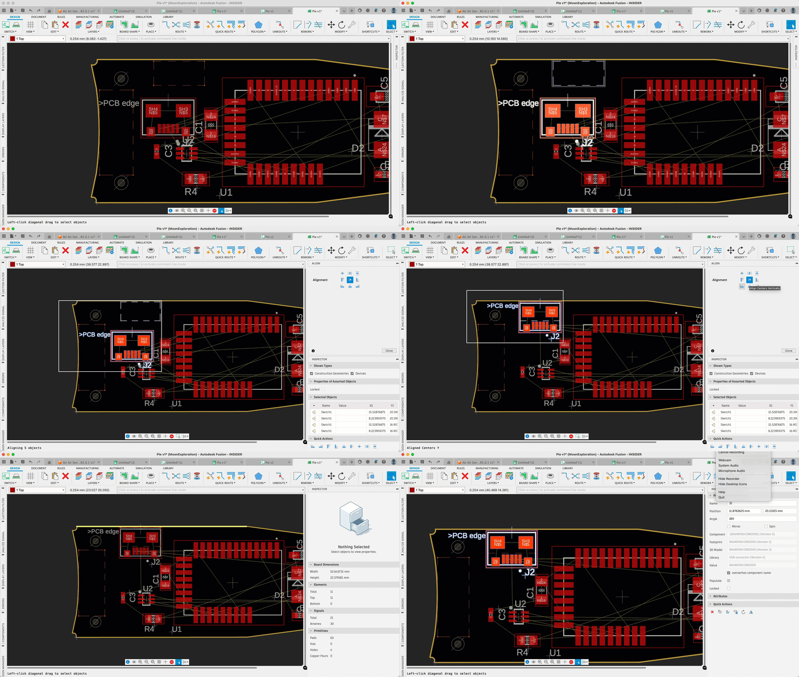
In the latest version of Fusion, we’ve introduced an enhancement that allows seamless alignment of PCB assets with construction lines defined in either the Fusion Design or 3D workspace. This feature supports the cohesive, integrated workflow that makes Autodesk Fusion ideal for consumer product design, bridging the mechanical and electronic engineering gap in a single, unified platform.
Fusion’s electromechanical capabilities eliminate the traditional hurdles of file conversion, enabling smoother collaboration across disciplines. The construction line feature allows mechanical engineers to draw reference lines and shapes directly on the PCB layout, guiding electronics engineers in precise component placement. This recent update will enable electronics engineers to leverage the Align command to accurately position assets along these construction lines, accelerating the design process by providing a clear reference for component rows, breakout holes, and more. This streamlined approach reduces design time and ensures higher accuracy and alignment for complex consumer electronics projects.
Learn how to Align Objects.
Allow Face Selection in PCB Hole in the 3D PCB workspace
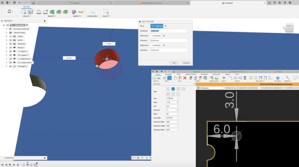
In the Fusion 3D PCB workspace, you can now choose the exact plane for placing holes, adopting the familiar behavior from the Design workspace. This approach enables reference capabilities for precise placement, which the 2D PCB editor will adopt. This enhancement ensures a smoother workflow between mechanical and electronic design, allowing you to seamlessly align mounting points and standoff locations, ultimately contributing to a more cohesive and manufacturable product design.
Quickroute follows DRC Custom Rules
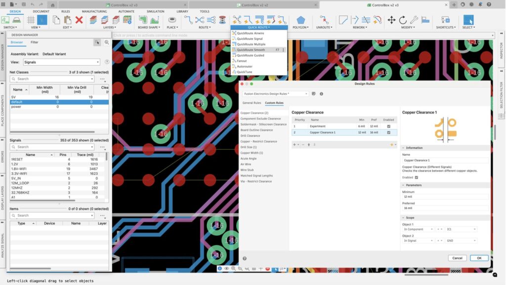
Our latest update has significantly improved PCB design constraints, moving from a single global setting to a more refined structure divided between Preferences and Design Rules. Design Rules now offer separate sections for General and Custom rules, with Custom rules introducing a range of flexible options to meet the specific constraints required by any board house or PCB complexity. Additionally, Fusion’s QuickRoute capabilities—a suite of interactive tools designed to streamline PCB routing—now fully support the custom rules defined in the Design Rules dialog, allowing faster, more efficient design completion with tools precisely tailored to your specifications.
Library Swap Update
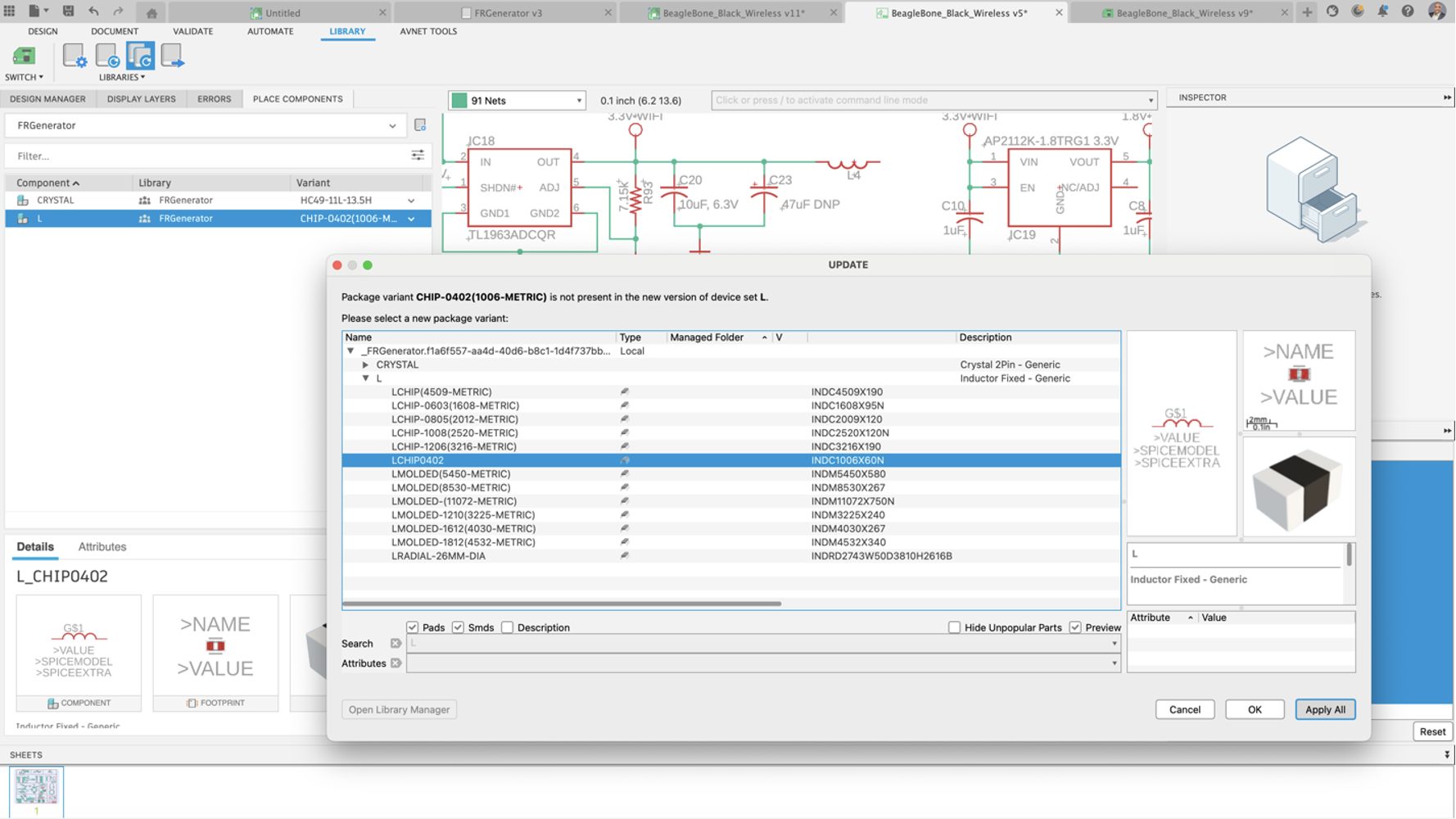
In consumer product electronics design, it’s common to encounter situations where components in the schematic need to be swapped for alternatives—whether due to better pricing, supply chain constraints, or changes in part availability that could impact manufacturing Timelines. Fusion’s Library Swap capabilities make this process seamless, allowing you to efficiently replace parts throughout the design with just a few clicks. In this update, the library update dialog box will prompt you to select a new package variant, “Apply All” option to all
Components of the design. Traditionally, you were prompted for each instance, and with this new implementation, updating the schematic with variant options became much more accessible.
Simulation
Injection Molding Simulation Material Database Updated (Simulation Extension)
The Injection Molding Simulation material database has been updated to give a more comprehensive database of both materials and manufacturers:
- Total number of New Materials added: 216
- Total number of Materials updated: 121
- Total number of Materials deleted: 9
- New Manufacturers added: 9
- Manufacturers deleted: 1
- New Total number of Materials: 13423
- New Total number of Manufacturers: 615
Manufacturing
Leads and Links Modifications (Manufacturing Extension)
A new toolpath modification is being introduced to the Manufacturing Extension, which allows the Leads and Links to be adjusted on a toolpath without full recalculation. Not only does this offer a significant reduction in programming time to adjust toolpaths, it also allows you to overcome issues that might be difficult or impossible to work-around by altering the strategy parameters alone.
The modification will allow all leads and links, or a manual selection, to be updated. You also will have control over the clearance geometry (plane, cylinder, sphere), as well as clearance and retract heights, start and end positions, rapid links, transitions, and leads.
The default leads and links modification parameters should in most cases be a close match to the base toolpath parameters, and it’s possible to create expressions in leads and links modifications to reference the base toolpath, the parent toolpath, or the tool.
When a lead is selected to be modified, Fusion will highlight the corresponding link to indicate that it will also be updated out of necessity to match the new lead.
Learn how to modify Leads and Links .
Machine/avoid surface support in Horizontal and Swarf strategies
The new table for machine and avoid surfaces, including fixture protection, is now added to the Horizontal and Swarf strategies. It revolutionizes how you use your toolpaths giving you greater control over what gets machined and doesn’t get machined.
Easier 4-axis Machining for 3D Milling Finishing Strategies (Manufacturing Extension)
The 4-axis Machining Type option is now available to all 3D finishing strategies for milling, making it much easier to use 4- or 4+1-axis machining. This is accompanied by options that make it easier to obtain safe linking moves on 4- and 5-axis toolpaths, enabling Heights to be defined with respect to a cylinder, sphere, or inclined plane.
Learn how to create a 4-Axis Toolpath.
Improvements to Flat Machining
Improvements have been made to approach moves on closed profile passes next to walls in the Flat machining toolpath. We now add a horizontal arc move with a slight incline to reduce the risk of the tool leaving marks on either the wall or the floor of the part as it enters and exits the profile pass.
We have also significantly reduced cases where the toolpath rolls around corners as it exits an open pocket. Instead, the toolpath will exit the pocket with a straight motion, leaving the sharp corner on the model intact.
Reduced Whisper Cuts in 3D Adaptive Minor Stepdowns

This November we are worked to help you reduce the amount of Whisper Cuts you encounter. We did this by reducing cuts that only remove a minuscule amount of material using an improved surface tessellation. If you encounter issues while using this enhancement the improved tessellation can be reverted using an optional feature called “Legacy surface tessellation”.
Visualization of Contact Normal
There is now the option of showing contact normals as well as tool axes in the Toolpath Data Dialogs settings. It will show the contact normals for each toolpath point on toolpaths that have contact normals available. This feature will help you better visualize the tool axis especially in multi-axis moves as well as help you determine if there is something potentially wrong with the underlying model data or triangulation
Probe Geometry Fitting Can Now be Used to Probe Stock (Manufacturing Extension)
Probe Geometry Fitting is an alternative probing method that extends the capability of Probe Geometry, allowing you to probe angled faces, holes and bosses that you would not be able to measure with standard probing cycles.
Within this update we have enhanced Probe Geometry Fitting to support the probing of stock (for example ‘Fixed size box’ or ‘Relative size cylinder’) by enabling the use of “Probe Mode-Stock” in the Geometry tab. This provides similar extended probing capability for measuring the geometry of the workpiece stock, for example probing with a Tool Orientation applied, or checking against asymmetric or unequal tolerances.
As with the initial release of ‘Probe Geometry Fitting’ you must import the measurements results into Fusion for evaluation, and you will need a postprocessor with ‘inspect surface’ capability.
Learn more about the Probe Geometry strategy.
Improved Silhouette Selection Support for Mesh Bodies
Silhouette selection now produces a more accurate boundary for mesh bodies. Previously the silhouette selection would sometimes create an oversized boundary that surrounded the mesh but did not closely follow its shape. Now the silhouette selection will give a more accurate boundary that closely follows the shape of the mesh. There is now a setting in Preferences (Legacy Mesh Silhouette) which allows you to restore the previous behavior if you find problems.
Improved Usage of Multiple Cores on Mac when Calculating Steep and Shallow and Toolpaths That Use Collision Avoidance. (Manufacturing Extension)
Previously, Mac users could only use four cores for calculating Steep and Shallow toolpaths and toolpaths with Collision Avoidance. We have now improved support for multi-core calculations on the Mac, lifting this restriction. Mac users will now utilize all cores on their machines when calculating these toolpaths.
Iscar Tool Advisor Add-In

The Iscar Tool Advisor add-in connects Fusion to the Iscar Tool Advisor, which helps recommend cutting tools based on the machine tool used, material cut, feature, part geometry and more. Each tool comes with the corresponding recommended feeds and speeds, to help provide a baseline to machine from and helps automate tooling selection for specific jobs.
Try it today by downloading the Iscar Tool Advisor add-in from the Autodesk app store.
Threading: Put Back Retraction Policy for “Use Canned Cycles” On
We now allow for minimum retraction between passes for a turning thread operation with canned cycles enabled.
Additive Manufacturing
Additive Manufacturing Process Simulation: Directional Part Removal from Build Plate (Manufacturing Extension)

The removal of the part from the build plate can now be simulated by directionally cutting in either the X direction or the Y direction, or with the default single-step removal. When directional removal is enabled, the build plate is gradually cut away over the course of four time steps near the end of the process simulation.
Learn more about Additive Manufacturing Process Simulation.
Duplicate Components for 3D Printing
You can now duplicate their components within the context of their 3D printers build area / volume. In the past, if you wanted to 3D print multiple copies of the same part, you had to duplicate your components ahead of creating an Additive Setup in the manufacture workspace. With this release, you can create additional copies of your components within the Additive setup.
The new Duplicate command creates instances of a selected component within the associated Manufacturing Model and adds the newly created components to the active Setup. There are 3 options to choose from when placing the new instances. You can create the new instances at the same location as the original one, so that you can rearrange them manually or automatically using Additive Arrange. Alternatively, you can use the bounding box method to create a pattern of parts in X, Y and Z axes. Or you can use the True shape algorithm we introduced with the September to create an array of parts along a single axis. The True Shape option gives the best outcome for keeping parts as close possible as the gap between the parts relies on a components True Shape instead of its Bounding Box.
Learn how to Duplicate Components.
Enhanced Post Processor and Machine Simulation
Looking for the latest post processors and machines updates? This November we released a ton of new updates and improvements to many of the open-source Post Processors and Machines we offer for free. Within this release you will find improvements to post processors including Generic Post Processors, Milling Post Processors, and Turning Post Processors. We also added new machines to our Machine Library, updated our Workholding library, and improved functionality around the Autodesk CAM Post Processor engine.
Learn what’s new for Post Processors and Machine Simulation this November.
Missed the August update? Learn what’s new for Post Processors and Machine Simulation from this past October.
API
API Support for Spun Profiles in Sketch
The API supports the new capability to create and edit spun profiles, which are commonly used as input for lathe operations in CAM.
Easy Access to Joint Positions
Previously, to get the position of a joint, as-built joint, or joint origin, inferring it from the geometry used to create the joint was necessary. Using the geometry to get the position wasn’t intuitive and there were problems if the geometry had been modified after the joint was created. The API now supports getting the positions directly by providing the geometryOneTransform and geometryTwoTransform properties on the Joint object and the transform property on the JointOrigin and AsBuiltJoint objects.
Thumbnail Creation
You can now generate thumbnails of components. Thumbnail creation uses the new createThumbnail method of the Component and FlatPatternComponent objects.
SelectionCommandInput Enhancements
A new capability has been added to the SelectionCommandInput. When there is more than one SelectionCommandInput on a command
dialog, only one SelectionCommandInput is active at a time. Previously, these inputs shared a single internal selection set. This means that each SelectionCommandInput can select entities, and each SelectionCommandInput remembers the entities that were selected while they were active. But this also means that once an entity is selected, it can’t be selected again because it is already in the shared selection set. The enhancement lets you specify for each SelectionCommandInput if it has its own selection set. If enabled, an entity selected by one SelectionCommandInput can be re-selected by another SelectionCommandInput. Defining this behavior is done using the hasDistinctSelectionSets property of the Command object. The default behavior for this property is false, so there is a single selection set, which was the previous behavior.
There is also an enhancement to control if the entities already selected when a command is started are made available to the SelectionCommandInputs of the command. The previous behavior is that they always were. Now, there is the isUseCurrentSelections property on the SelectionCommandInput object that lets you choose if they’ll be considered or not. Setting this property to False will completely ignore the current selections.
Redefine the Original Transform of an Occurrence
When you add a component (Occurrence) to a design, you can reposition it during the initial placement. Fusion now supports editing the initial position of an occurrence after it has been placed. The API also supports this through the new initialTransform property of the Occurrence object.
Not all occurrences have an editable initial position. For example, if you pattern an occurrence, the initial position of the occurrences created for the pattern cannot be changed. The isVaildForEditInitialPosition property tells you if the initial position can be modified.
Use ASM to Quickly Calculate the Outline of a Body
The TemporaryBRepManager has been enhanced by adding the createProjectedBodyOutline method. This method is similar to the Project command in a sketch, which supports projecting a body onto a sketch to create the outline of the body as the sketch curves. With the new method, no persistent entities are created, and the result is a temporary BRepBody that contains one or more faces representing the “shadow” of the body.
This method uses ASM’s (Autodesk Shape Manager) fast calculation capability to calculate the outline of a body as it is projected onto a specified plane. This is much faster and more robust than using the Project command. There are cases where the Project command does not result in closed curves. This new method should return more reliable results, although there are cases where the result will be approximated using a tolerance you define.
Fixes
Forum Reported Fixes:
Your feedback matters to us, and we’re dedicated to improving your experience with every update. You’ve shared your thoughts, and we’ve listened and acted. Within each workspace our teams are constantly working to make your experience within Fusion as smooth as possible. If you haven’t already, now is a great chance to check out what forum reported issues we have addressed in the November update.
Check out what we fixed in Design.
Learn what we fixed in Electronics.
Discover what we fixed in Manufacturing.
Additional Fixes:
Usability:
- Mac Launch Hang Issue: We resolved an issue that caused Fusion to hang during launch due to loading the protein library on Mac.
- Fixed being unable to use short names in the Browser: We fixed an issue that prevented renaming a Component Browser node if the new name was shorter than the original (e.g. from Body1 to Body, from 1234 to 1).
- [Windows] Parameters window no longer shrinks when dragging Fusion: We fixed a Windows-only issue where the Parameters dialog (and possibly others) would shrink in window size as you dragged the Fusion app frame.
- [Windows] Undocked command windows will no longer dance around when dragging the Fusion app window: We fixed an issue with the Windows client where undocked command windows would shake as the main Fusion app frame was moved. They should now stay put. Mac users were unaffected, as their command windows hide when the app frame moves.
- Fixed browser nodes being stuck highlighted after deleting a feature from the timeline: We fixed a bug where deleting a feature from the timeline caused the body nodes in the model browser utilizing that feature to remain in a permanently-highlighted state.
- Fixed right-click Timeline Feature menus when right-clicking on a browser body: We fixed an issue where right-clicking a body in the browser would show the menu for the timeline if a feature was highlighted.
Manufacturing:
- Align Extensions for Geometry Features gives Accurate Preview: “Align Extensions for Geometry Features” was added in the July 2023 release to enhance open chain selections- it allows you to change multiple extension values at the same time, and a graphical preview helps you to set the appropriate value for the extensions. A recent regression meant that the graphical preview was not displayed. This is now fixed and the graphical preview is displayed correctly.
- Fix for Rest Machining with Empty Toolpaths: Rest machining keeps track of the remaining stock from previous operations but there has been a problem with empty toolpaths. (Empty operations or toolpaths are common in automated CAM programming when particular features are absent.) An empty toolpath can be ignored for rest machining purposes and the remaining stock should be carried through from the previous operation. There was a bug where empty toolpaths did affect the stock model, making it unusable for subsequent operations (the workaround was to suppress the empty toolpath.) The issue is now fixed.
Electronics:
- Invalid Airwire Issue Resolved: Invalid airwire will appear when the user has top and bottom polygons connected with a via stitch object. The airwire should not appear because the top and bottom copper-pour polygons are connected through the vias in the via stitch object.
- Design Rules Check Fix: Design Rules Check cannot flag the overlap between spline outlines and route lines.
- Board Design Manager Fix: Fix the crash in Board Design Manager when swapping the current library with the user’s choice. This random crash usually required many library swap operations before it happened.
- Referenced Geometry Fix: When creating an associative PCB from a sketch with referenced geometry, it can be the case that after push to 2D PCB is executed, some of the holes on the 3d PCB do not show correctly, leading to confusion regarding whether the holes still exist, etc. This customer reported the bug has been fixed, and the holes should now show correctaly.
- Improved Place Panel: The place panel will now remember your last selected variant for each component and the last selected attribute set for each variant.
- Document Tab Fixed: The untitled Electronic document tab will now automatically close when opening an existing document.
Insider Program
Do you want to engage more with the Autodesk community, use Insider previews, and test out the latest build one month before it’s released to the general public? Check out the Fusion Insider program! The Autodesk Fusion Insider Program enables you to access the next version of Fusion and all the new features, improvements, and fixes, 3-4 weeks before the general public. As a member, you’ll gain inside knowledge of when we are deploying an update, what’s new, and what’s coming next . You will also have the opportunity to join exclusive events, try pre-release functionality, and give feedback straight to the product teams.
Note: When you work in the Insider build, you are working with your existing Production data. If you are collaborating with people with production builds, they will not be able to access your Insider designs. This is because designs saved on Insider are not backwards compatible with production versions. (This will only happen for the Insider weeks since the general public will catch up on official release).