V.2.0.4854
October 19 Update fixes the following issues:
- Crash on opening files having a Boundary Fill feature created after the September 18 update
- Exporting a F3D from Fusion Team yielded a F3Z instead.
- CAM tool libraries were not sorted the first time you accessed them, whereas selecting a different library and then going back to the first library will cause it to be sorted correctly.
V.2.0.4801
“A must see – 2 thumbs up!” – a self-proclaimed YouTube-obsessed critic
[toc]
Generative Design
🎁 New! Generative Design is now in Fusion 360
Previously, Generative Design in Fusion 360 meant that you clicked on the “Generate” button in toolbar and it took you to a separate app experience where you did all your setup and definitions there. Once you were happy with a result, you had to export your results out and bring it back into Fusion 360.

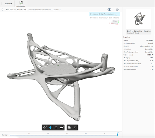
Now when you access your workspace switcher (as a commercial subscriber), you’ll see a new workspace called Generative Design. This is where you can perform all your Generative Design related workflows, define constraints to explore iterations. Once you’ve selected the result you want to keep, save it, bring it into the Model workspace, and start cleaning it up with T-Spline editing tools in the Sculpt environment, without leaving the software even once.
And yes, now that Generative Design is a workspace, it works natively on macOS as well.
Edit Model
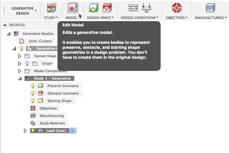
Inside the Generative Designs workspace, you’ll have access to the Edit model workflow. This experience is just like the Simplify workflow in the Simulation workspace. You will be able to make the necessary tweaks to your design or create your design space geometry without changing your original design model.
Design Space, Constraints, Loads, and Objectives
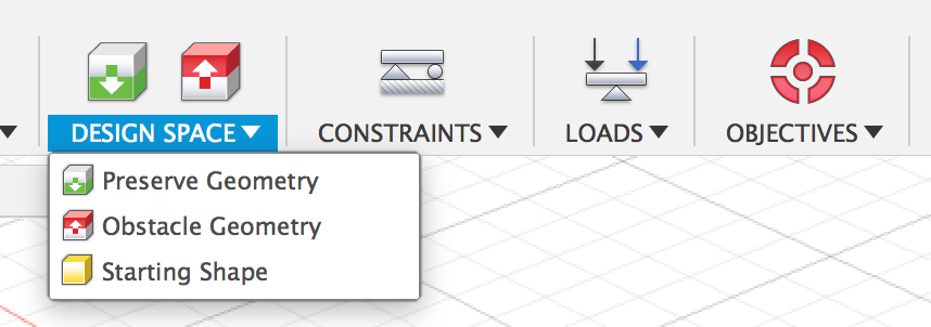
The Design Space and design conditions are just the beginning of what you are telling the Generative Design solver to help you develop a design. Simply put, Preserve Geometry let’s you tell Fusion 36y0 where you must have material in your design, Obstacle Geometry is where you absolutely cannot have material and the Starting Shape (if you want to use one) will point the Generative Design solver in a certain direction. The design conditions represent how the design will work, i.e. where is it held and how hard are you going to push on it. Lastly, the Objectives will allow you to tell the system how strong your design needs to be.
Manufacturing Recommendations
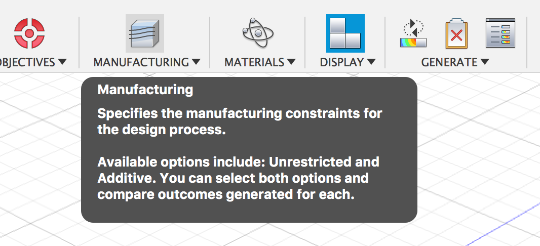
What’s so smart about Generative Design is that it is manufacturing process aware. Now that it is Fusion 360, it can recommend outcomes based on advanced additive or 3 and/or 5 axis milling processes considerations.

Explore your options
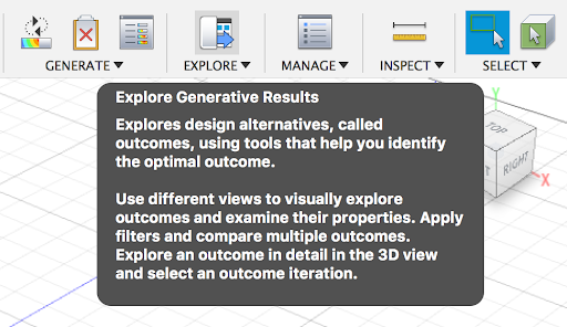
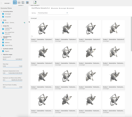
Previously you explored your options in a separate Generative Design window. Now you do it in Fusion 360 by accessing it through the Explore icon in the toolbar. The same tools, filters, and result view types will be there for you to toggle through.
Resources to help you get started
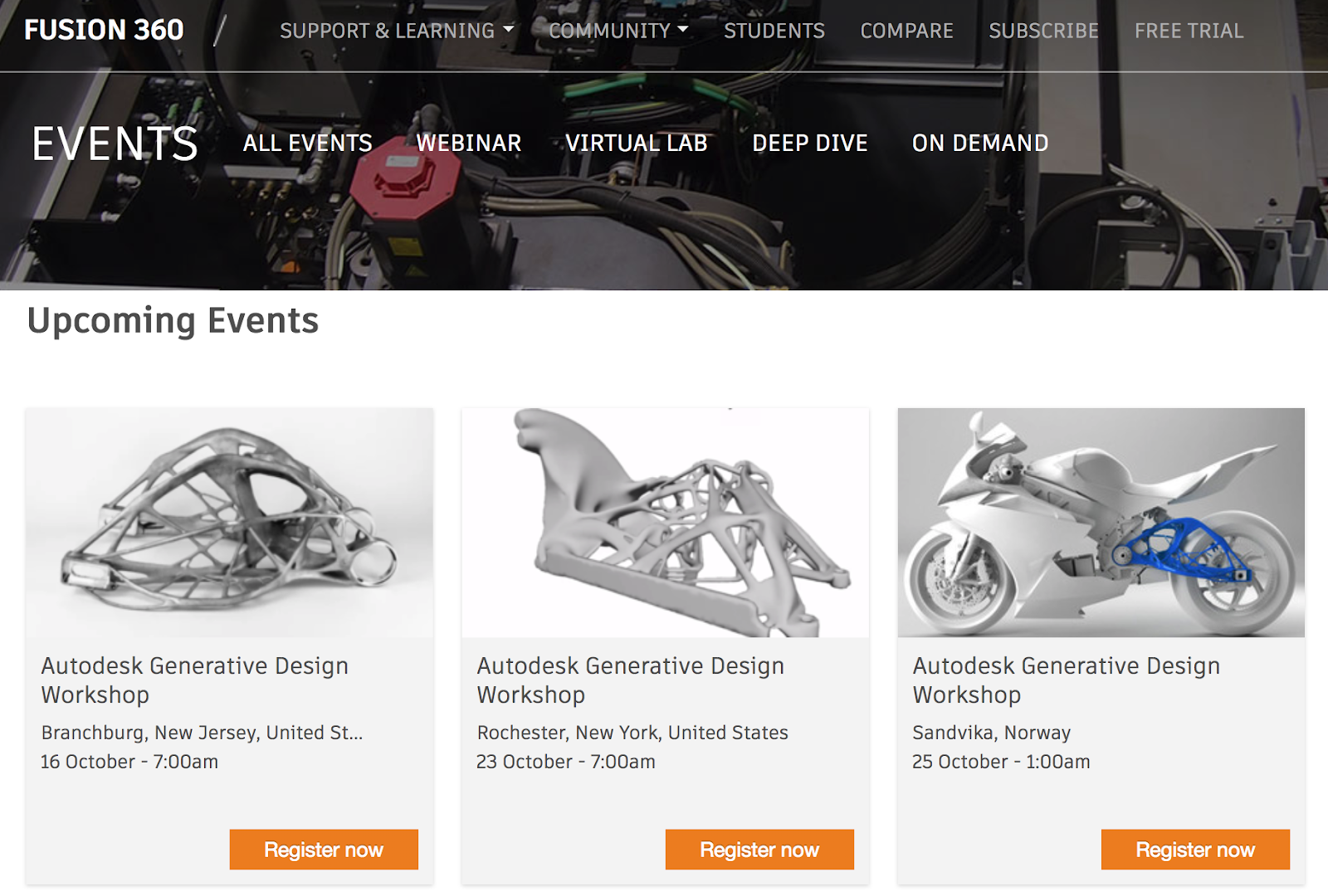
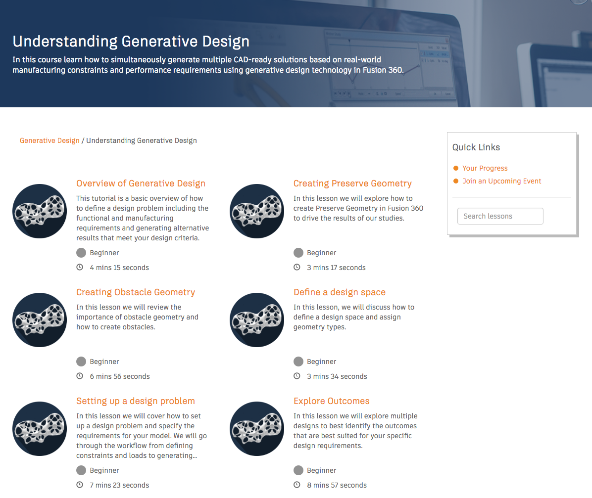
This stuff goes pretty deep, and that’s why we have a bunch of content and training out there on how to work with Generative Design, best practices, as well as workflow pro-tips. Check out the Generative Design Help pages as well as these ongoing online webinars and onsite workshops, lead by our cracking team of Generative Design experts (you may recognize some of them, since they are YouTube all-stars as well).
➡️ Workshops | Register to attend one near you
➡️ Webinars | Register now
➡️ Getting Started Tutorials | Start by learning
Generative Design Editing
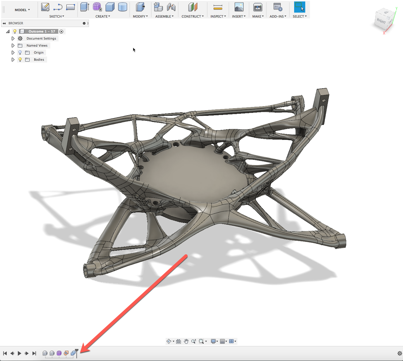
One of the main benefits of Generative Design being inside Fusion 360 is that the outcomes you chose to work with are fully editable with the modeling tools available in Fusion 360. It’ll come in as a T-Spline body and appear right in your parametric timeline. From there, you can edit the T-Spline with all the Sculpt tools at your disposal.
🎁 New! Erase and Fill tool
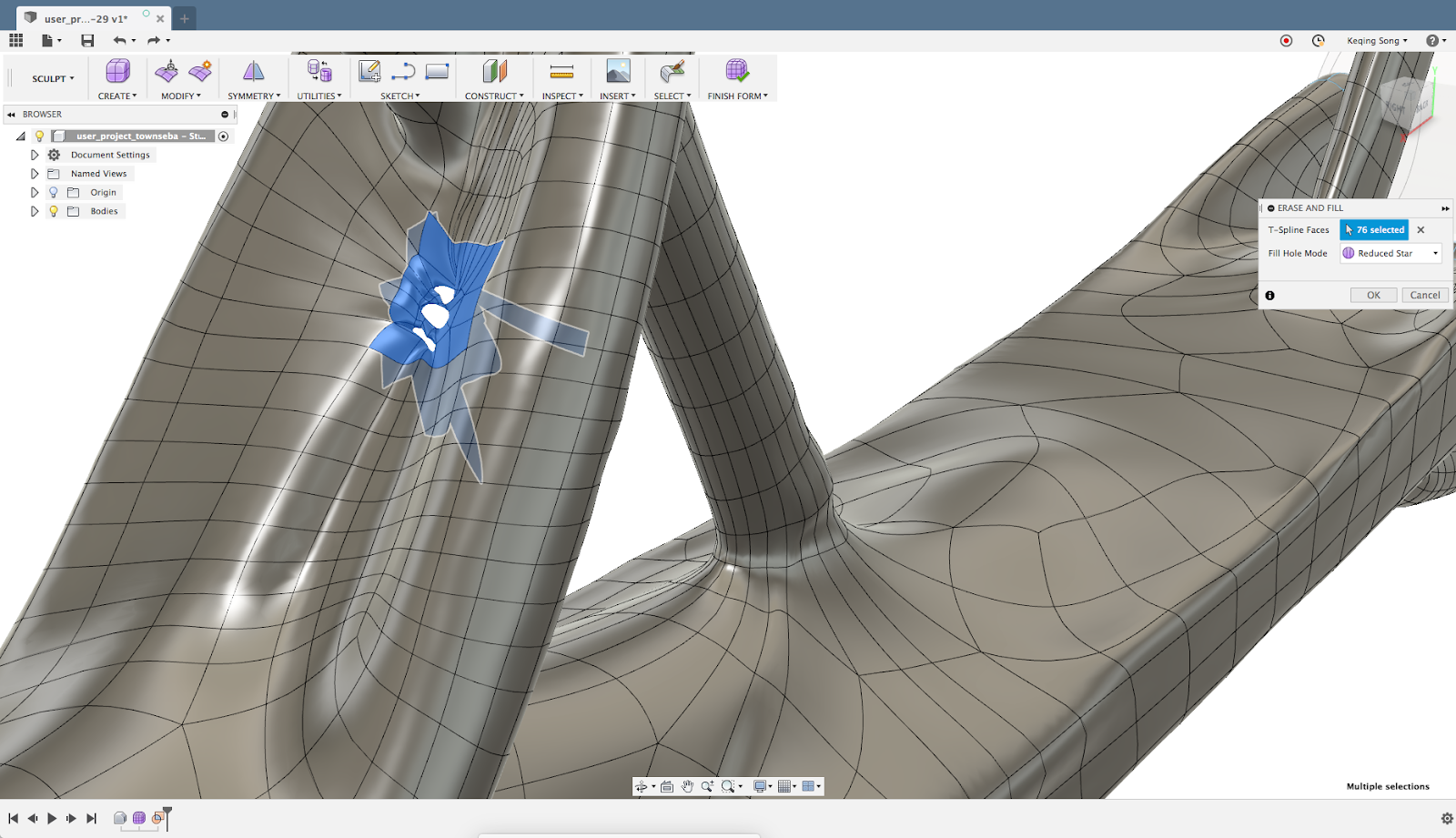
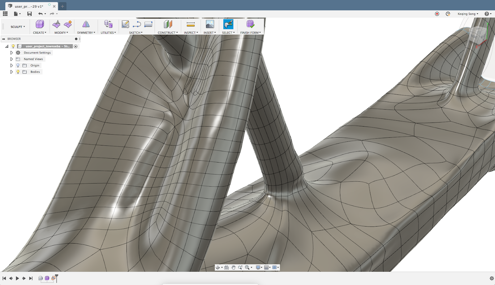
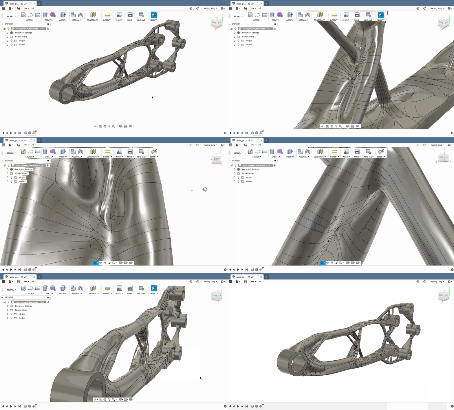
We’ve also added a tool that gives you the ability to select an area of the T-Spline body that may be overly complicated/not that important to the overall integrity of the part, erase the area, and fill it with faces that are more logical to the selected area with a Reduced Star or Fill Star.
🎁 New! Better Manipulator Re-orientation
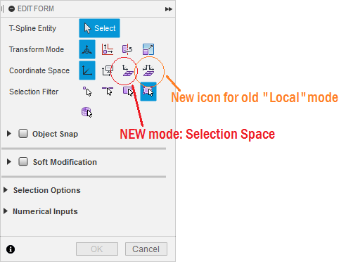
Now when you’re in Edit Form, you can also re-orient the manipulators in the direction of a selected strut or pipe, so that editing geometry becomes more predictable. Under the Coordinate Space option, you’ll see a new mode called “Selection Space”, next to “Local Per Entity”.

Selection Space transforms selected objects as a group in the direction of the axis of the manipulator. Local Per Entity transforms each of the selected objects locally, relative to the direct of the axis of the manipulator. There’s no special command for this to happen – just toggle the re-orient option in the floating dialog and the manipulators will naturally snap to the most logical direction.
🎁 New! Hole/Strut selection
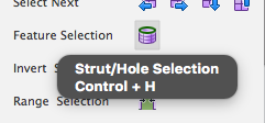
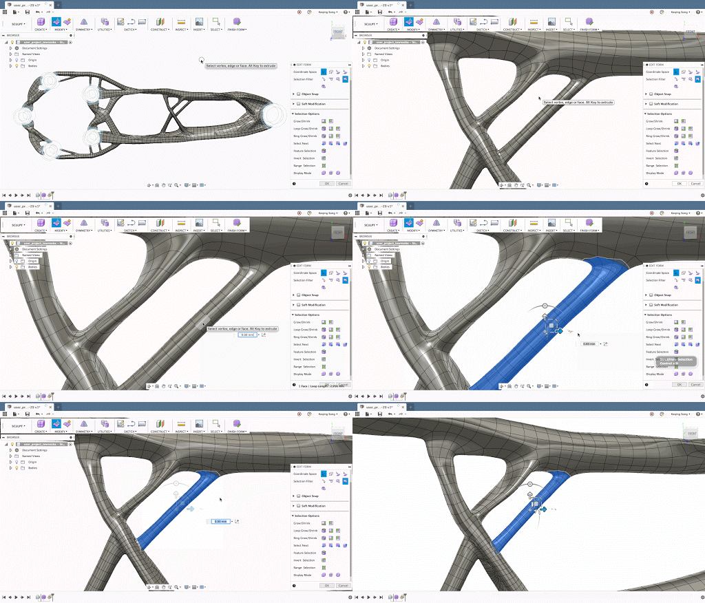
This handy selection tool enables you to select a strut or a tube that starts from one side and terminates (unevenly) at the other side. Instead of selecting each face individually (and painfully), hit CTRL+H (ALT + H for Windows) and voila, the whole strut is selected.
Derive Designs
This is a new powerful workflow that has a ton of advantages, and sets us up for future projects. Consider this: today if you insert a design into another design, you can’t edit the inserted design unless you “break link”, which in that case, all associativity to the original is lost. This means that if the original design changes for whatever reason, you will not be able to update the inserted version and will have to manually do the change since the link has been broken.
Here’s an example of how Derive shines
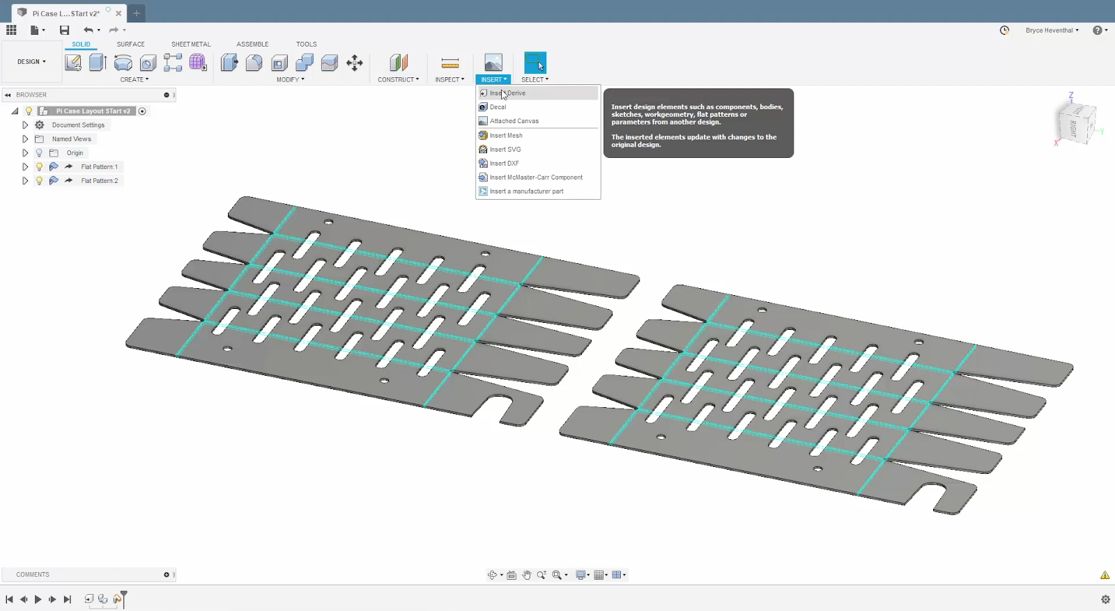
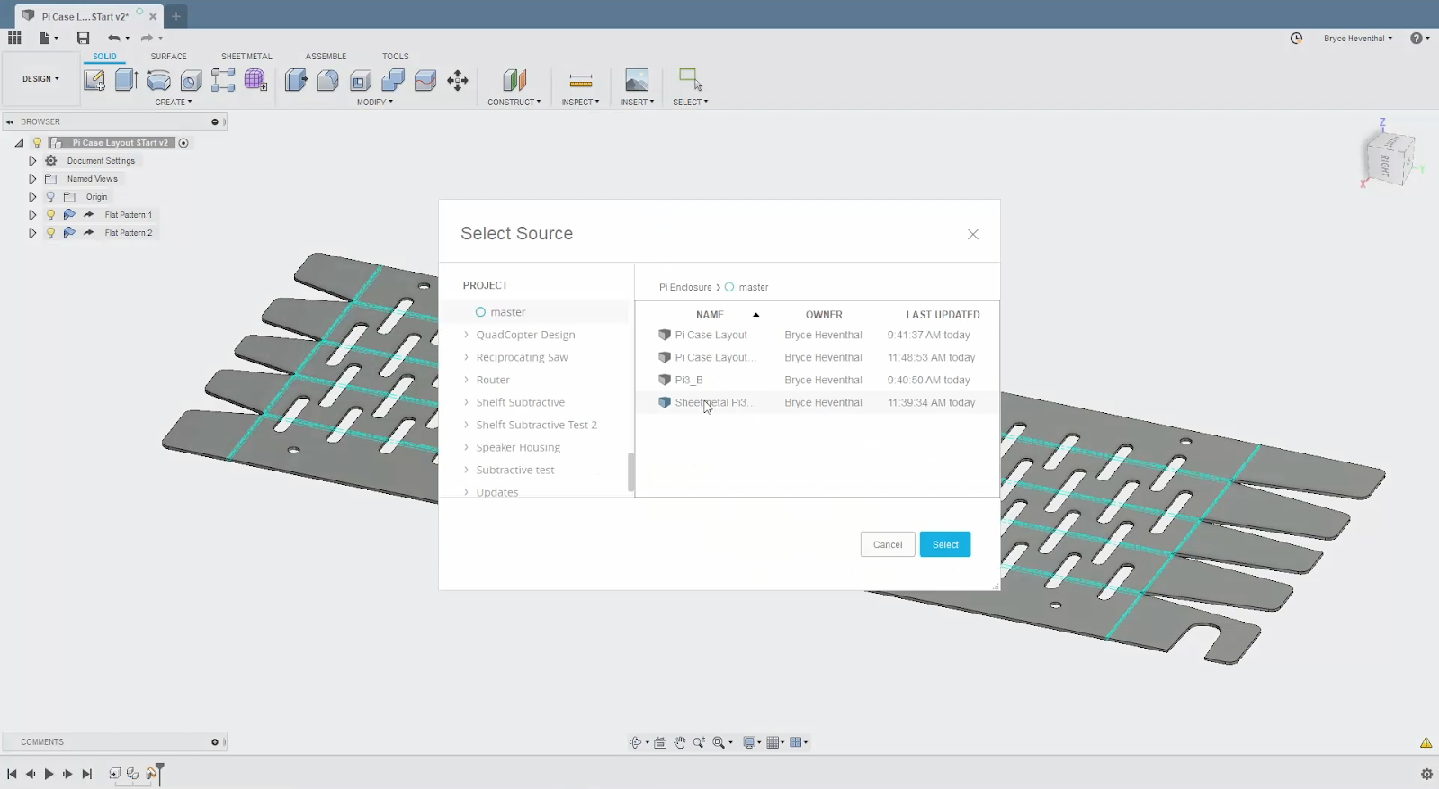
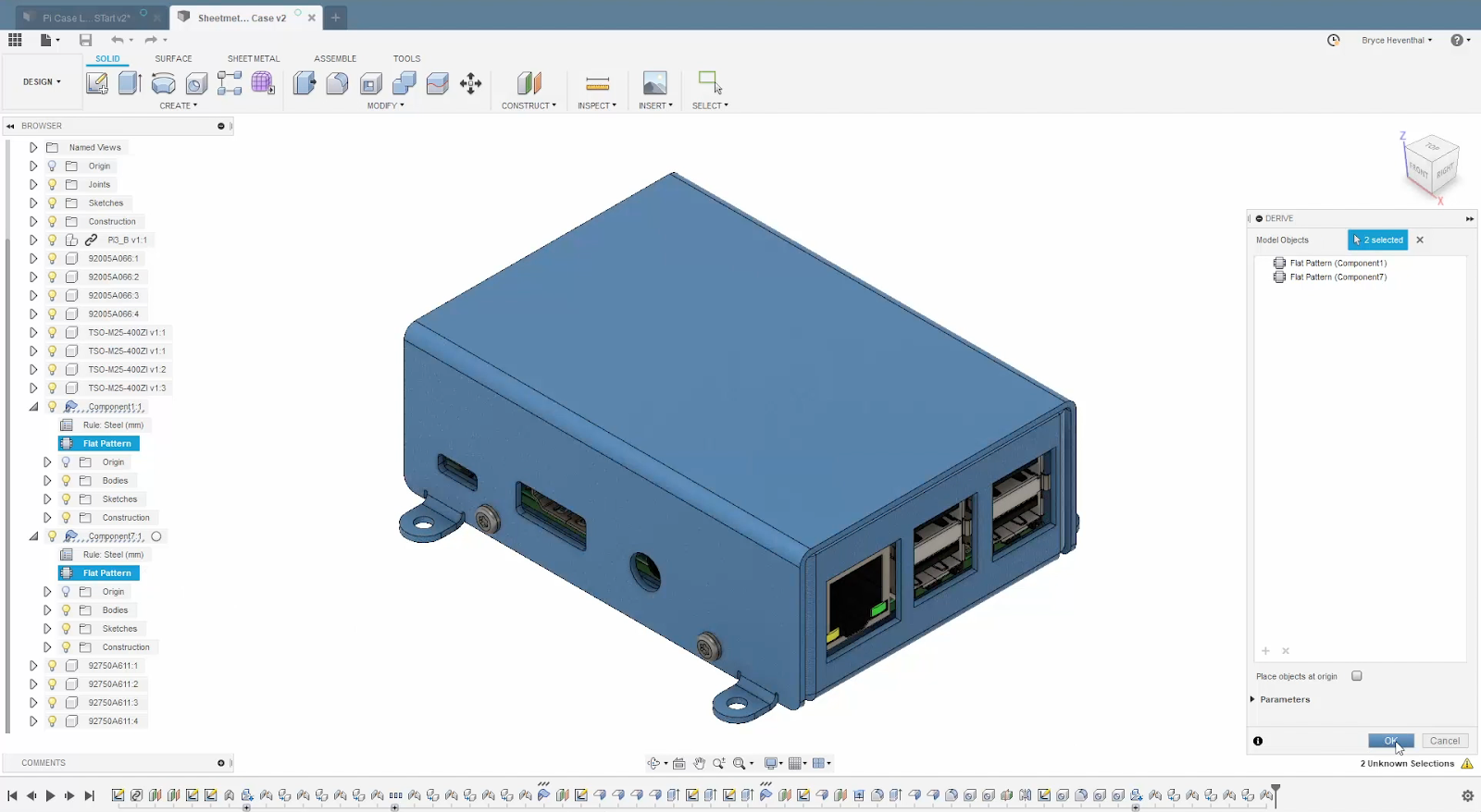
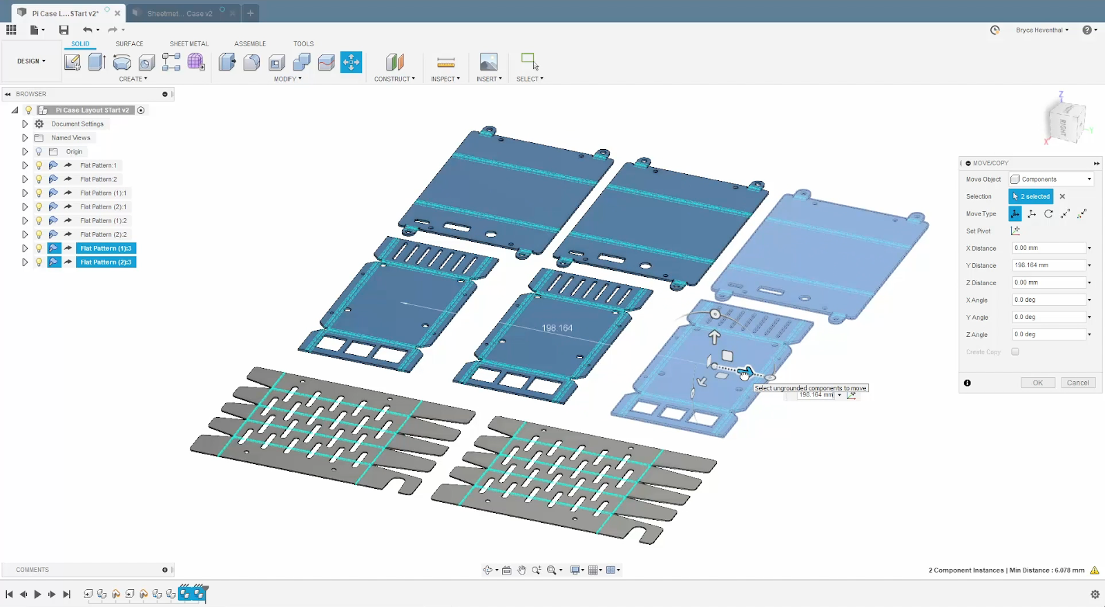
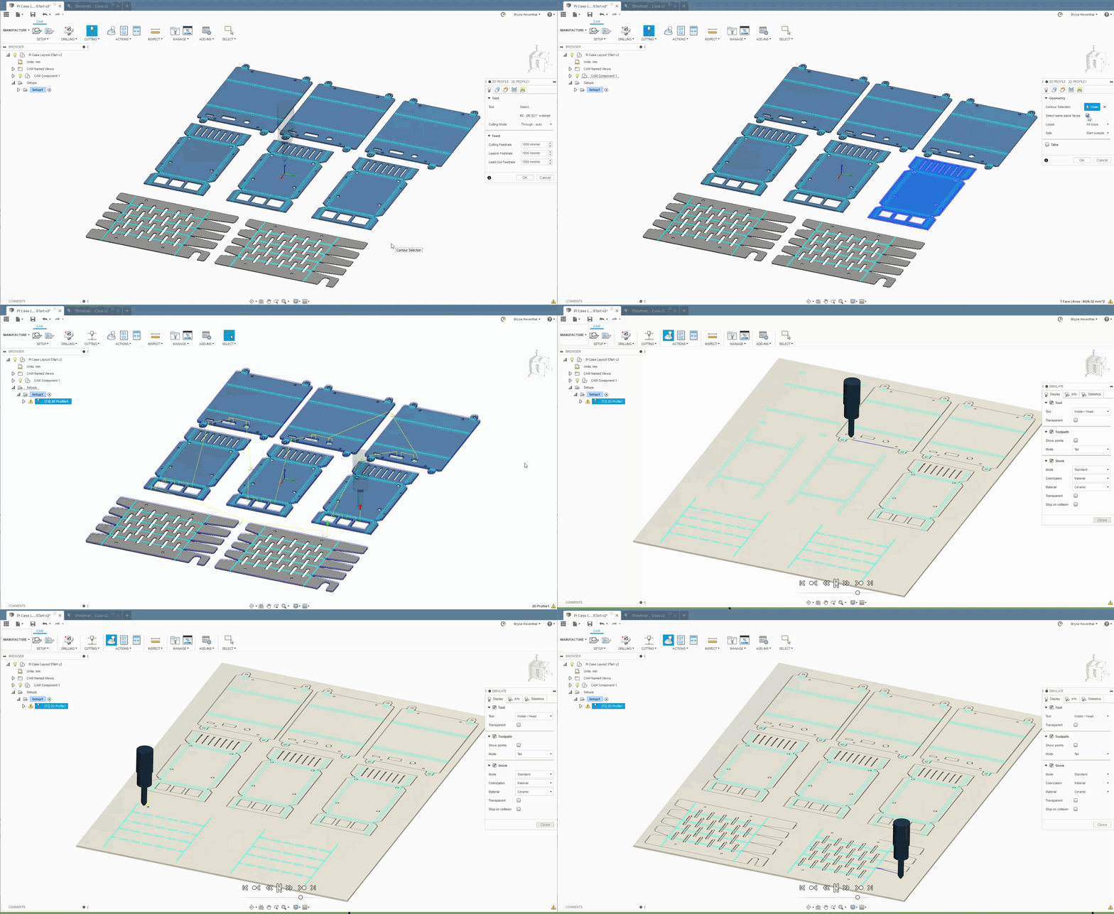
Bryce showed a great example (in the video embedded above) of how all of this can benefit your manufacturing workflow. Say that you’re working in a team where you’ve been tasked to go cut out an sheet metal enclosure. The flat pattern designs exist in separate projects, but with derive, you can perform an Insert Derive, grab the appropriate parts from each project, and organize them in the correct layout for 2D cutting in your own derived document.
Once you’re happy with the layout, create the tool-paths, and then simulate them to make sure everything is in good shape for physical cutting.
Changes Are Inevitable
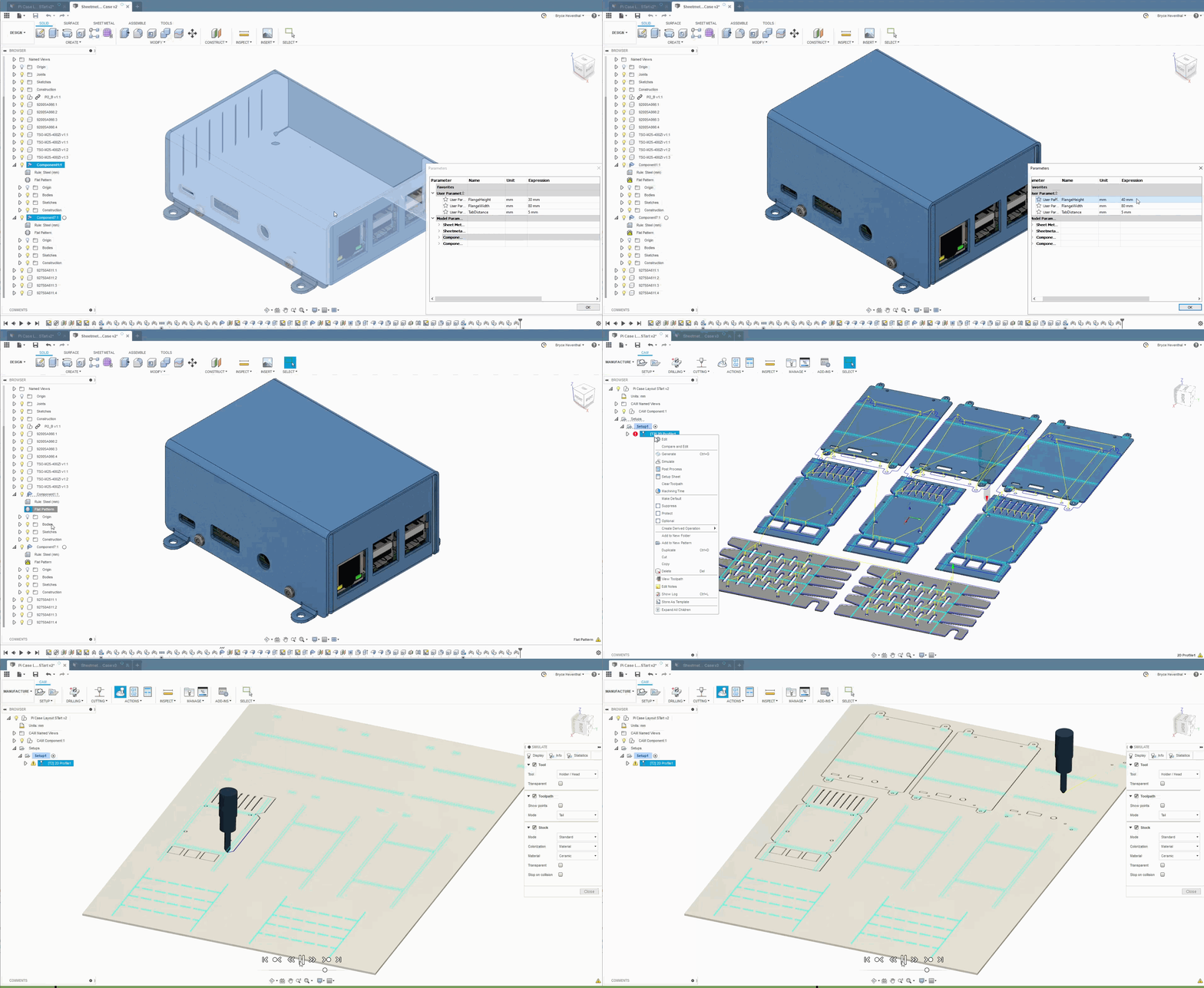
Let’s face it, design changes will always happen. Here’s where Derive really shines. If a change is made to any of the sheet metal parts, your derived flat patterns are associatively linked to the source, which means all you have to do get the change updates is a simple click-of-a-button. Your layout updates, your tool-paths update, and all is dandy in the world.

Driven Designs let’s you derive bodies, components, sub-assemblies, sketches, construction geometry, joints, sheet metal flat patterns and even parameters. You can derive them from one project and insert into/create a new project with the derived part in them, while maintaining associativity with the original design. Best of all, you can also edit the derived part without affecting the original while associativity is maintained.
So how do you do this? There are two ways to derive a part – Create Derive or Insert Derive.
🎁 New! Create Derive can be found under the Create drop-down menu in the Model workspace.
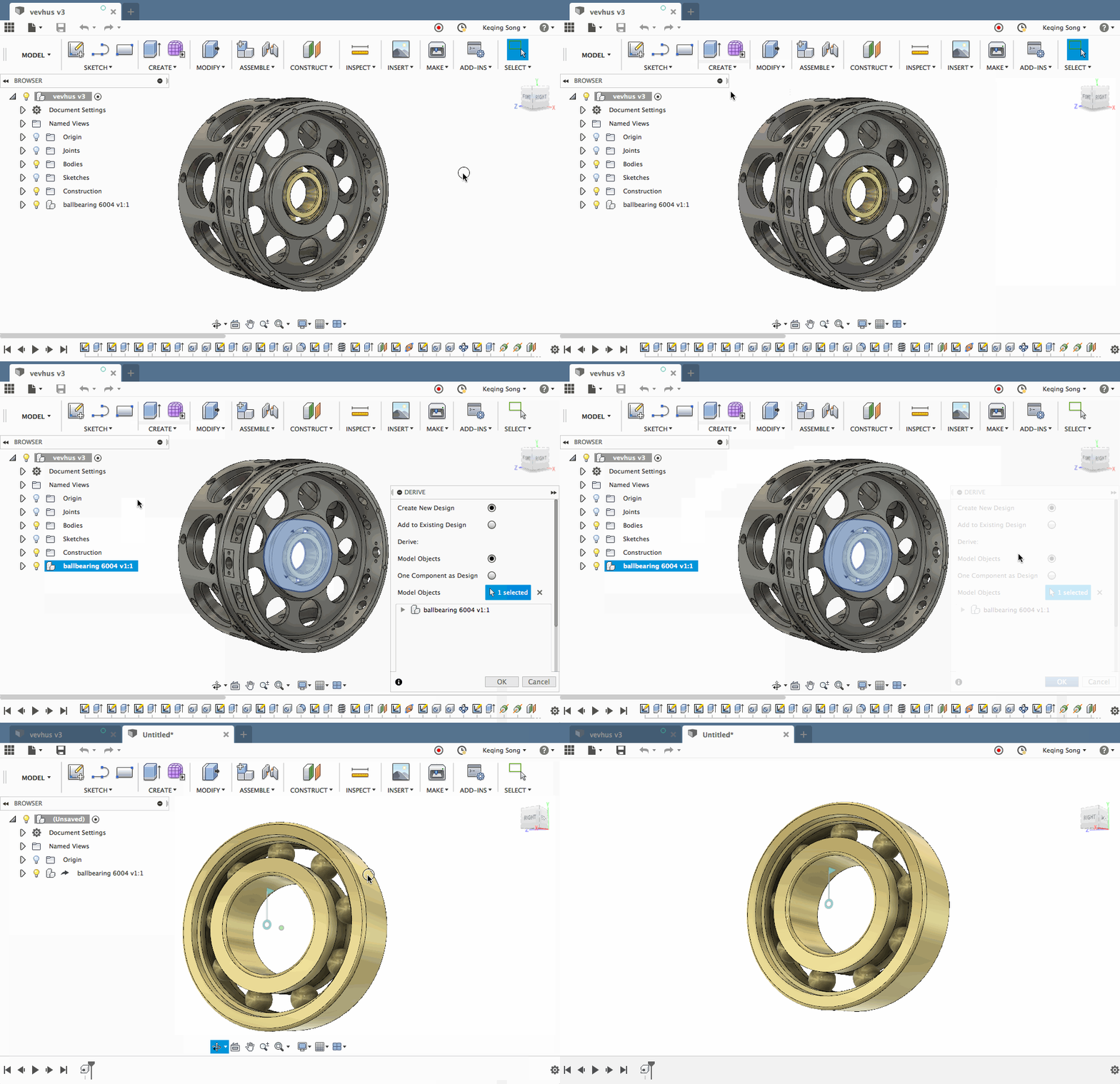
Invoking Create Derive is like pushing the whatever you want to derive into something else. It will give you the options to select the part you can like to “derive” out. That’s not all; you can also decide whether you want to that derived part to become a new design, or be placed in the existing one.
If you select the option where it will become a new design, you can go another level deeper and tell it to either be at the root level, or be a component under the root level.
🎁 New! Insert Derive is located under the Insert drop-down menu of the toolbar. Unlike Create Derive, Insert Derive lets you insert (or more like pull) a part from another project into your existing design as a derived part.
*Protip: How you select your part determine what gets included in your selection
There is a subtle difference between how you select the part, and being aware of this can save you a lot of time. Derive has the ability to include bodies, components, as well as their related sketches and parameters.
Selecting in Canvas = bodies only
If you select your part by clicking the geometry in the canvas, you are just selecting the part itself, without any reference .
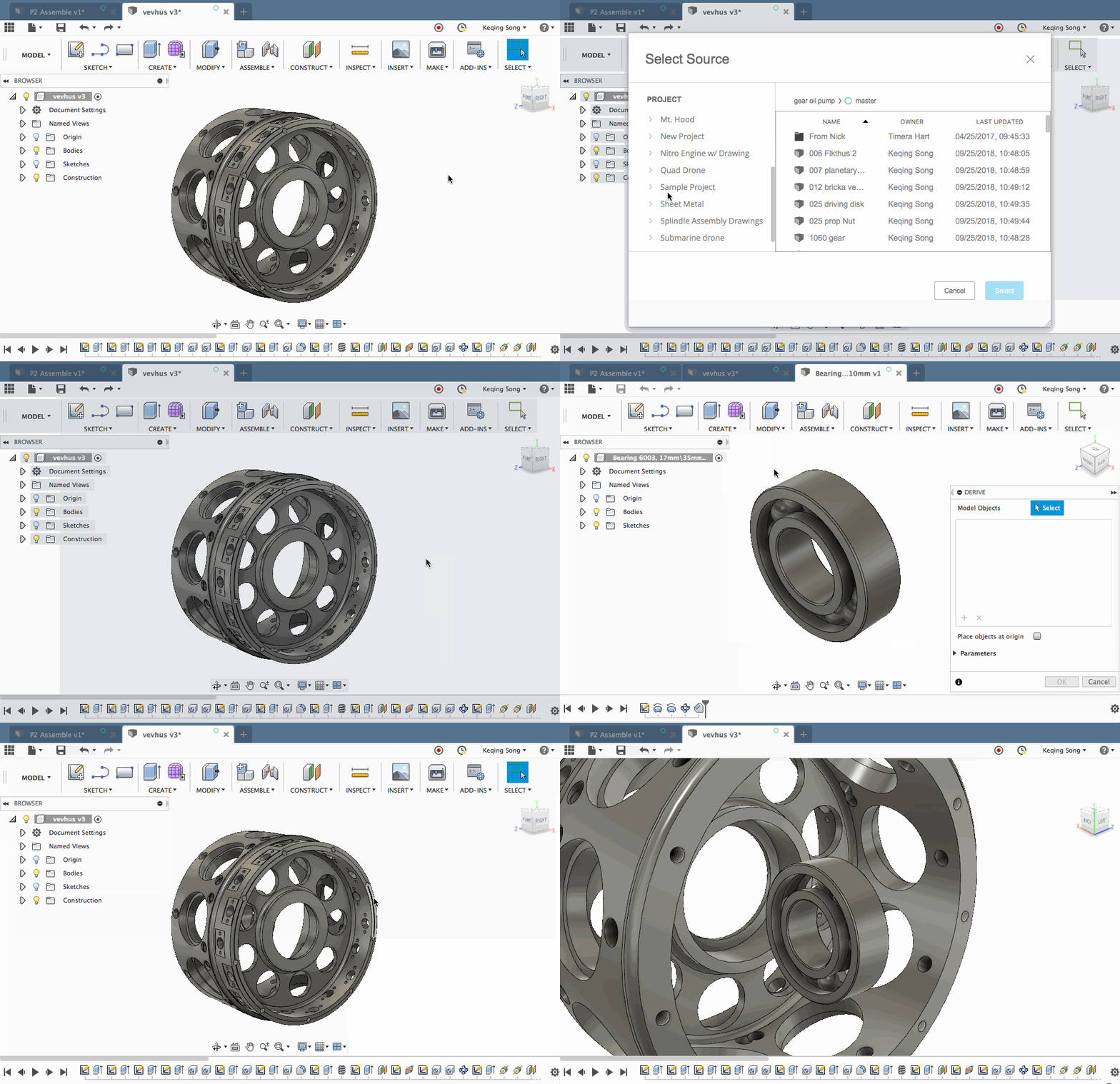
Selecting from Browser = bodies, sketches, joints
If you select your by clicking on the entity in the browser, that you are selecting the part as well as its related sketches and joints.
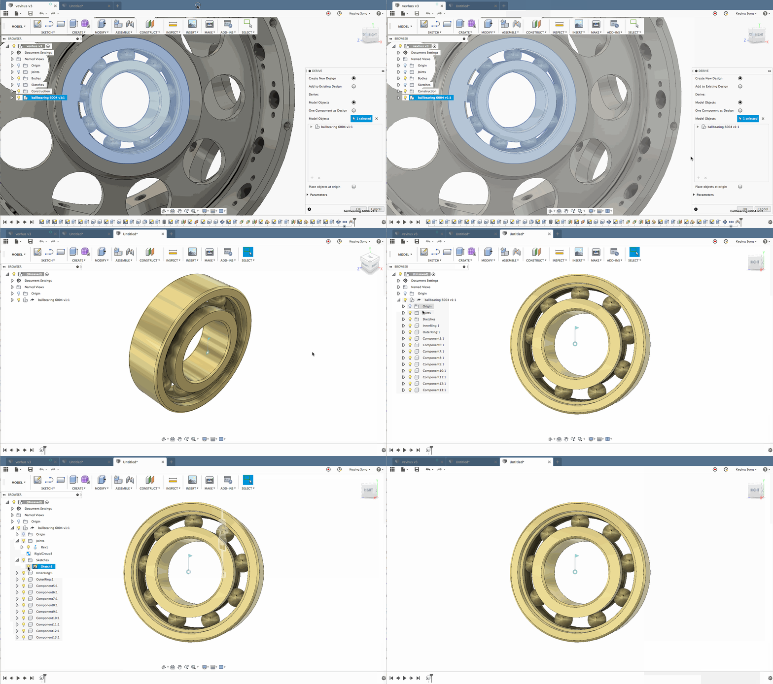
In short, Derive enables your team to be more flexible, gives you more control over the task at hand, and saves you all the trouble of getting a part updated due to changes made upstream. There are so many other examples out there where Derive can help you, and we’d love to see you put this functionality into use and hear about your experiences.
Modeling
👍 Improved! Fillet Command
We’ve talked the talk, and now we’re walking the walk. Previously the Fillet command felt clumsy when you wanted to fillet multiple edges with different radii for each set of edges – there wasn’t a good way to do in a one clean sweep. We also had a separate Rule Fillet command, which felt disconnected from the Fillet toolset.
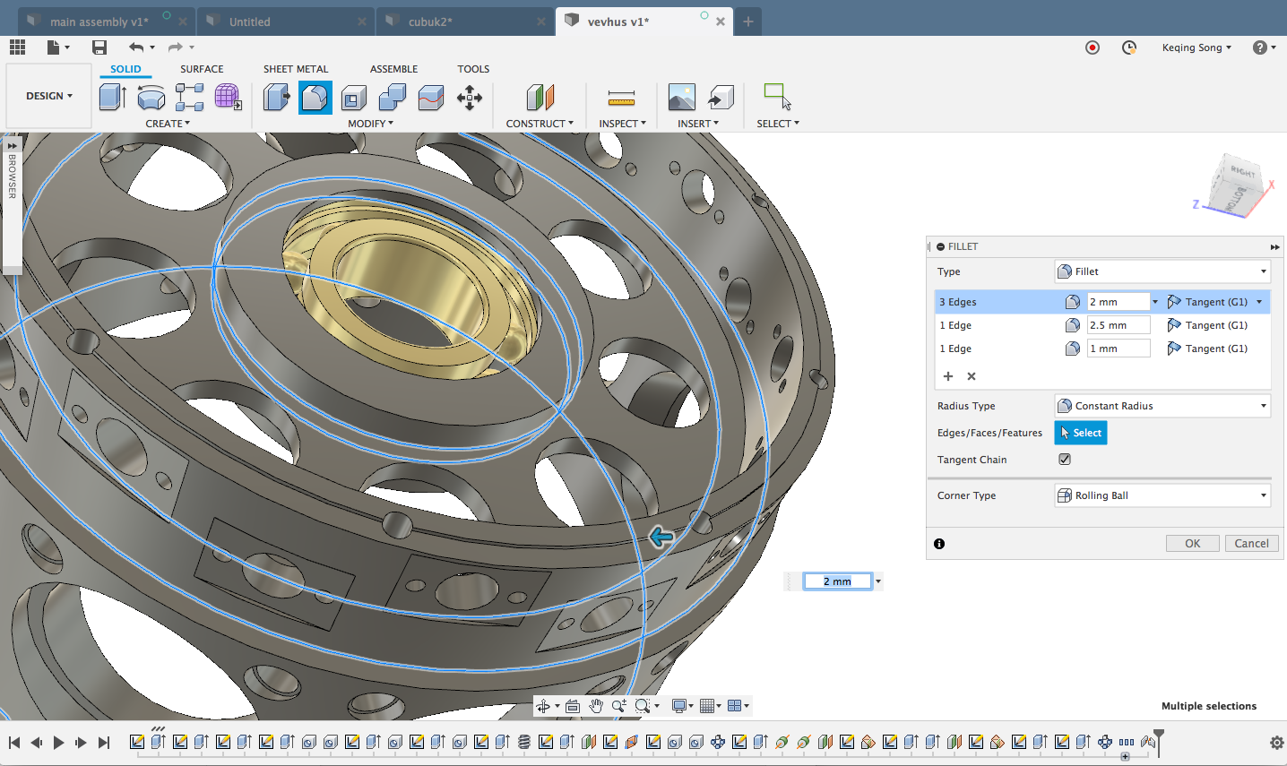
Now the Fillet command has been improved to support multi-selections, different radius values for your selection groups, tangency types, Radius types, and Corner types, all in one. Oh yeah, Rule Fillet is now also part of this command: you can select a face of a your part and it’ll fillet the edges all at once.
🎁 New! Smooth tool

If your Generative Design output or T-Spline bodies have bumps/superfluous geometry that you’d like to get rid of, Fusion 360 now has a tool called Smooth that lets you do exactly that. You can find it in the Sculpt environment under the Modify drop-down menu. Protip: the Smooth tool works well on surfaces with a high frequency of bumps (like really bumpy). If the face you’re trying to smooth only have a few bumps, it may not be as useful. We’ll continue to improve on its performance in future updates.
💪 Notable Fixes:
- Apparently if you tried to drag bodies into a new group folder in your bodies folder, it didn’t actually move them. Yet if you preselected them and moved them with the right-click menu, they move over just fine. Now dragging them works just as well.
- Sakane.taisetsu reported an issue where he was experiencing some instability when switching to the Simulation workspace or when he was trying to save a file. We worked with his design and found some bad behavior around how Fusion 360 was handling the design. This is now fixed!
- There was typo in the Split Body Help section of the command, where the word Sketch was written incorrectly. Whoops…this was embarrassing. Now it’s all good.
- We fixed a crash issue that occurred when you doubled clicked on a timeline feature when Boundary Fill Edit window was active. Now when you do it, it will just activate the new edit action you started instead of crashing.
Sketching
👍 Improve! Sketch Projection Behaviors
Back in July, Jeff Strater posted in the forum asking for some feedback around some Sketch Projection enhancements we’ve been thinking about. We’ve been inundated with positive comments, and confirmed that we were on the right track. This update includes a number of improvements to Sketch Projections worthy of jumping for joy.
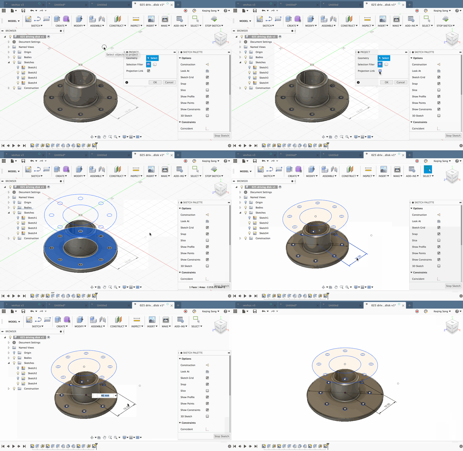
- Canceling a projection does the right thing
chrisYBGLU reported a wonky behavior where if you canceled a projection of a sketch, the projection still remained visible, which was totally confusing. Now when you cancel a projection, the projection goes away and you’re out of the command.
- Preselect + add selection for projection
Previously you couldn’t do this, but now you can. Preselect geometry before you invoke the Project command and also add on to your selection while the command is active. Winning.
- Unlink projection from source
Another thing you couldn’t do before, but now you can link/unlink the projected geometry from the source. If Projection Link is unchecked, any changes you make to the source sketch will not affect the projected sketch. Yaasss.
💪 Fixed:
We were told that if the name of the file you were trying to export had a period followed by some text and then the extension, Fusion 360 omitted whatever that was between the period and the extension (for example, 3d.print.f3d would end up being 3d.f3d, omitting the word “print”). Well that’s embarrassing – sorry about that.
2D Drawings
💪 Issues fixed:
- Blank Canvas when opening a drawing
There was an odd instance where when you entered the 2D Drawings workspace, your drawings tools loaded fine in the toolbar but the canvas remained blank. No sheets, no views. Just an empty white canvas that stared back at you. Turns out there were something wrong with calls being made to a certain font family and no one was home. They are now back and everything loads as expected.
- Title block didn’t support non-English characters well
inoue 4 A 825 reported on our Japanese forum that the title block was having trouble displaying Japanese characters and instead of asking us for guidance, it decided to show a bunch of question marks instead. That definitely got our attention. Hey, at least it’s honest. Now it’s caught up with Japanese and display the language just fine.
- Existing title blocks didn’t import correctly
Michael.charpin and endlesscustom found some wonky behavior with their title blocks where, when they tried to import their existing title block templates over to Fusion 360, it wasn’t able to pull everything over, and at times it ended up with an empty title block altogether. We fixed the leaky bucket and now importing your existing AutoCAD title blocks will come through without a hitch.
- 2D Drawings environment didn’t launch in some cases
Zillflor and others have told us about an issue where, for whatever reason unbeknownst to them, 2D Drawings workspace wasn’t launching when they invoked it from the workspace switcher. Related to Windows 7, we got this sorted out and now 2D Drawings launches as it should.
- Angular dimensions displayed distance units in addition to degrees
Apparently there was a bug that added a distance unit of in or mm in to the degrees value, depending on which one you’ve set as your default. Such mischief. Luckily Crueby1 caught the bug redhanded, and now it’s gone for good.
- Table cells didn’t grab focus
Another weird issue found by niklavs was when you tried to enter values into a table cell, Fusion 360 was distracted and didn’t give focus to the cell you were on unless you explicitly clicked on the cell. This resulted in you typing a bunch of values for nothing. Our bad. This is now fixed.
CAM
👍 Improved! Turning Strategy
- Home Position > Safe Z
The “Home Position” parameter in the Setup dialog was renamed to “Safe Z”. The reasoning behind this is that in a machinist’s vernacular, the term “Home Position” is frequently used to refer to the tool-post home position, which is where the tool-post retracts when you run either the G28 or G53 command on the machine. However, the intent behind the usage of the “Home Position” parameter in Fusion was to set a minimal “safe” Z position that a tool could retract to between machining operations in order to clear any interference in terms of unfinished material or machine parts before machining the next operation. 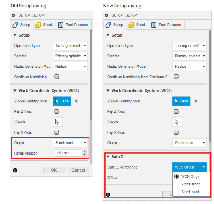
- Parametric Safe Z
Previously, in the setup, the “Home Position” was referenced with respect to the WCS Origin. This was a problem in certain use case scenarios, for example, when a user might want to attach the WCS Origin to the back of the model but reference the home position with respect to the front of the stock. The new Safe Z can now not only be referenced with respect to the WCS Origin (old behavior) but also either the front or the back of the stock.
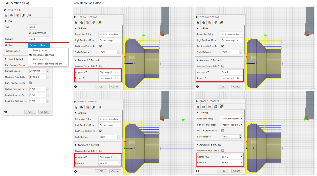
- Approach and Retract Z
The “Go Home” parameter in each turning operation has been removed. In its place, the Linking tab of every turning operation now has an “Approach & Retract” section. This is where the user can specify the Z position of the tool before and after every operation. The approach Z position can either be set to the first tool-path point or Safe Z. The retract Z position can be set to either the last tool-path point or Safe Z. For an inside threading operation the retract Z will always be set to the Safe Z in order to minimize the possibility of a crash. 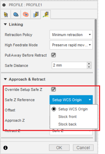
- Overriding Setup Safe Z in each operation
If the user sets either the Approach Z position or the Retract Z position of a turning operation to Safe Z, then the user can also choose whether to use the Safe Z value set in the Setup dialog, or to override it for the operation. This is useful in certain use case scenarios, for example, if an operation uses a longer tool that requires a longer retract in Z to clear unfinished material than the Safe Z value set in the Setup dialog then the user can override it and set it to a different value for the operation.
🎁 New! Manufacture workspace Preview
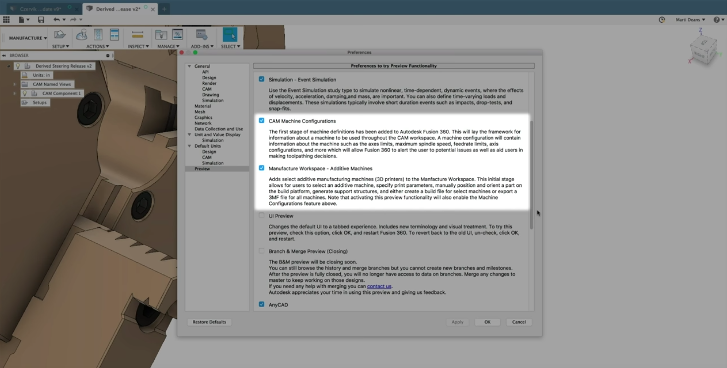
As mentioned in our roadmap update posted no long ago, we’re introducing a new preview called the Manufacture Workspace. You can turn it on, along with the Machine Configurations Preview, in the Preview section of your preferences.
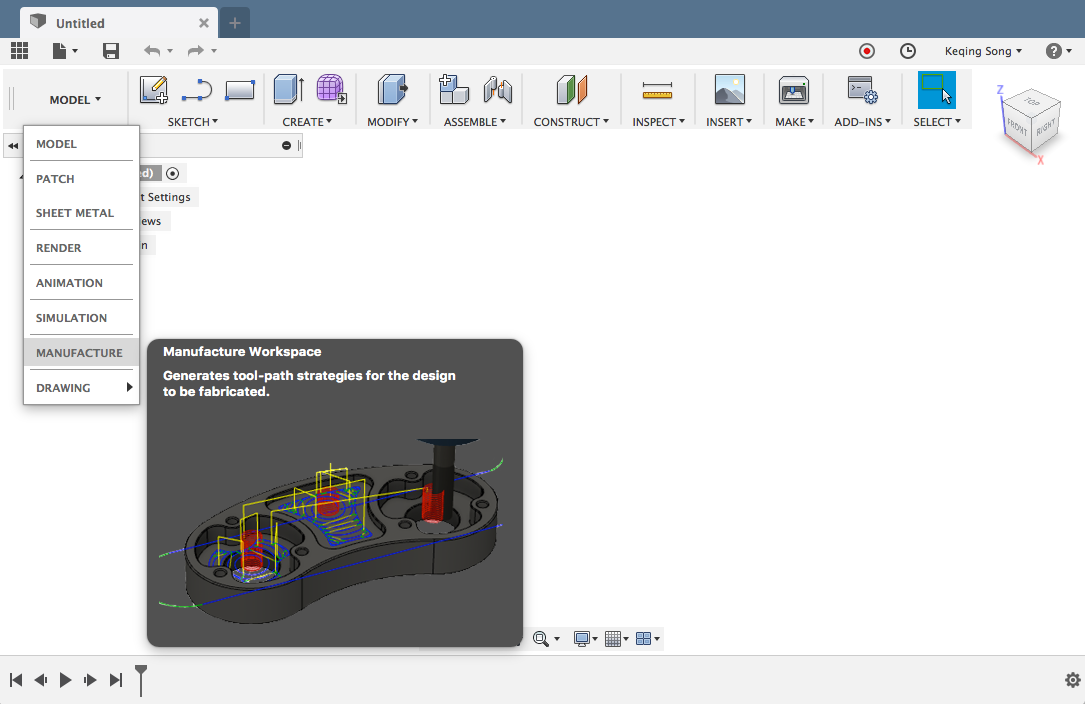
For those of you who live in the CAM workspace, you’ll notice right away that the toolbar has a lot less tools shown upfront. Don’t fret – this doesn’t mean that we removed a bunch of tools, it just means that they currently don’t pertain to the task at hand. This the Manufacture workspace includes subtractive as well as additive workflows, the first step to get started is to create a setup.

In most cases, the toolbar in Fusion 360’s workspaces are set up in a way where the first tool at the left is the tool to start a workflow with. In Model, it’s Sketch. In Manufacture, it’s Setup. If you’re doing subtractive manufacturing, this will be the exact same workflow as you were used to. Create a setup, set your Z, select the tools, edit your parameters, and then pick the strategy for the right job.
If you’re doing advanced additive manufacturing, this is where things get awesome. In the Machine Configuration selection dialog in your job setup workflow, you now have the option to select Additive as a manufacturing option.
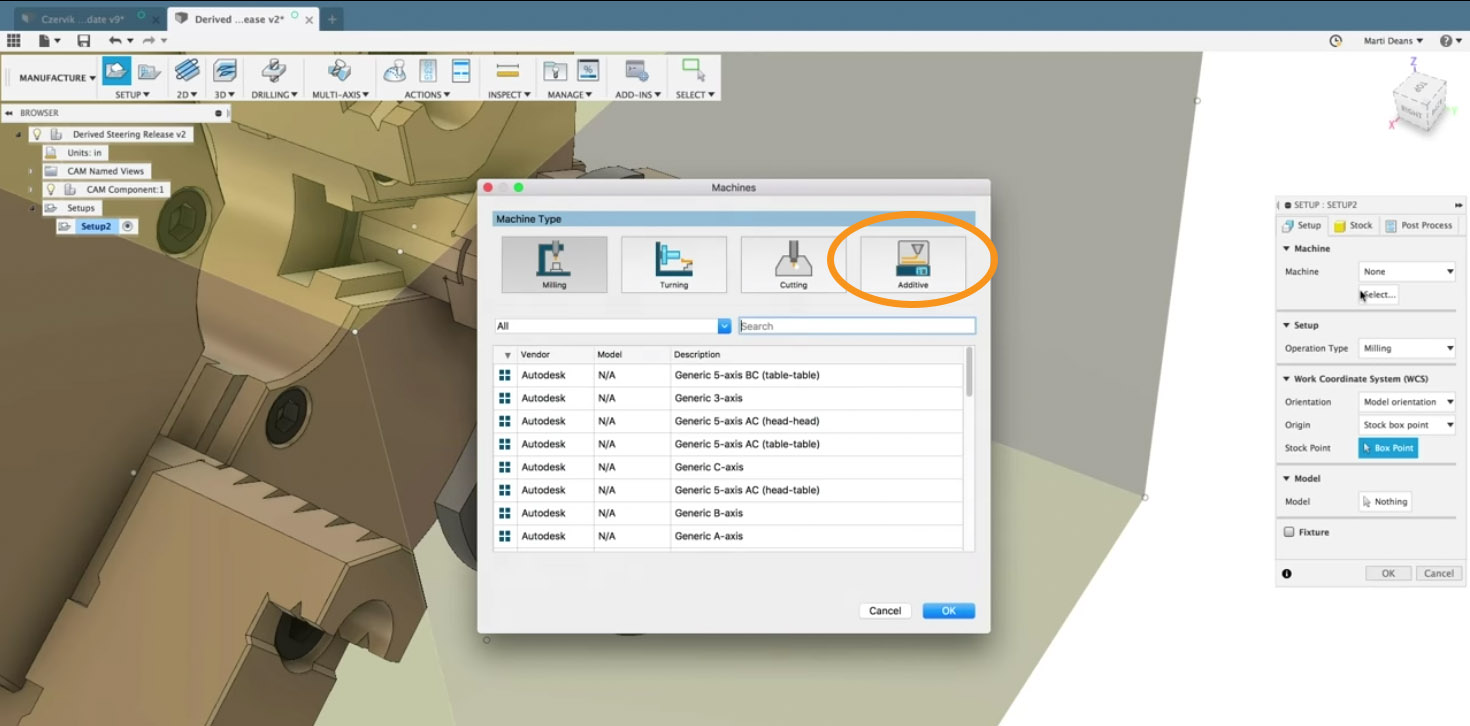
Additive metal manufacturing opens up a new world of strategies, enabling you to select the appropriate machine configuration, re-orient/reposition your part to the print bed just like any other 3D Print job, and give it the necessary supports for the print to be successful.


Once you’ve selected the support that best suits your part, you’ll get a preview of the supports right away.

The best part of about having additive and subtractive capabilities in one workspace is that you can manage both strategies all in the same experience, without needing to jump through hoops to get one section of the part printed and another section of the part drilled, like part above, for example.
What an update! There are a lot of new functionality being introduced this time around, and we’re already working on projects for the next update. In the meantime, give these workflows a try and let us know what you think, how they benefit your day-to-day processes, and how we can improve them for the future. We’re also planning on a few deep dive articles to help you get a better understanding of the new workflows available, best-practices on how to approach them, and how to think differently. Keep an eye out for them on our blog. Again, thanks for the continued support and we look forward to hearing from you!
Keqing and the Fusion 360 Team
